
I want to pile up some leaf debris in the corners. I downloaded some autumn leaves from 3dsky but once again I need a way to randomize which image texture gets used on each leaf.
The way I did this before is a royal pain.
I’ll try the geometry nodes + material id suggestion:
AO Node: “Loading render kernels (may take a FEW minutes the first time)” … it’s been like 7 minutes.
hey! how long as the AO node been working in EEVEE???
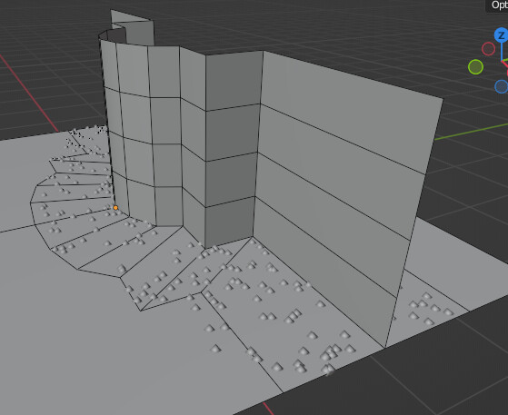
For the grunge in the crevice where the wall meets the floor I’m trying to make an object that is just an edge that follows the bottom of the wall and stores Geometry Proximity Distance as a named attribute. I can mix that with the textures to get darkness. It requires some manual geometry to control the extent of the affected area along with some manipulation of the gradient.


I can manipulate the gradient in shader nodes but can’t figure out a way to do it in geometry nodes to use it to have the amount and size of the leaves decrease as they move away from the wall.
@stray I don’t know what you mean by " if it uses assigned values instead of proximity "

I’m getting a nearly totally even distribution over the area.

I tried manipulating the range various ways and it just always seems to give a value of 1 over the entire desired area (even without the multiply).
GN proximity to corner edge.blend (187.9 KB)
C:\Users\thinsoldier\Downloads\3D Downloads\3dsky.org\Autumn leaves osienniie_list_ia
Sorry, I should have phrased it better ![]()
What I meant, if you assign values manually instead of using Proximity node, like Vertex Paint or Weights.
I’m not in the mood for painting the scene I want to use this effect on (or any future scenes where I might reuse it). Really hoping to figure out a way to have Distribute Points On Faces just fade out the amount of points as you get further away from the edges of a guide object.
Step 1
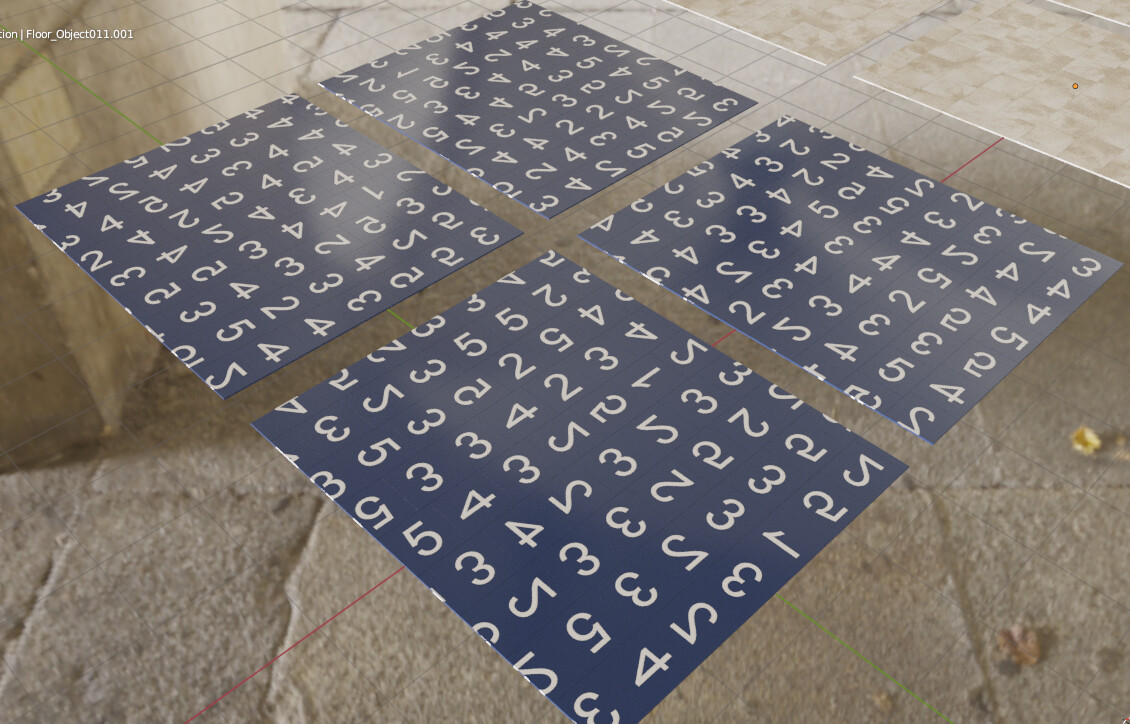
The obj file imports as a single object:

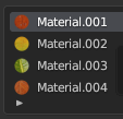
Make a material for each image:
Without Island Index each face will get a different material:

Faces on the same mesh island (not UV island, also known as mesh shell) share the same Mesh Island Index so all faces on an island will share the same material.

Duplicated the original object and put it in a collection.
Edit mode, Select All, P, Separate By Loose Parts.
Select all in collection, set origin to geometry.
Unfortunately this sets the origin of some leaves above the point where they would rest on the ground:

Is there a way to automatically move the verts of the object up until all verts are above the original z position of the lowest vert on the object? Or above the position of the origin point?
Is there a way to procedurally move all verts of the object up until they are all above the original z location of the Object origin?
Step 2
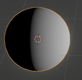
Isolate 1 direction from the Position to create a gradient:
![]()
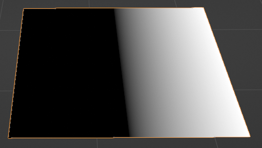


Is there a way to skip Step 1 and just randomly assign materials to material-less individual leaf objects in the collection?
Why does NOTHING work as expected on a default plane with only 4 vertices. Image textures have distortion. Geometry Nodes have no results/output. Nothing behaves as expected unless you subdivide the plane a few times. WHY? Do other programs have this same problem?
Does this look more like what you need? Your ground had no subdivisions enough so, I changed it by a subdivided plane, and I made some changes to the nodes as well.

GN proximity to corner edge.blend (283.5 KB)
Edit. Also added a curve, so you can change the “shape” of the distribution of the leaves in conjuntcion to the map range node. I think that helps a lot.


I don’t understand why Distribute Points On Faces needs so many subdivisions.
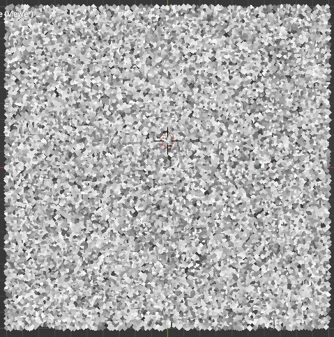
This is a single face with 6000 points distributed on it.
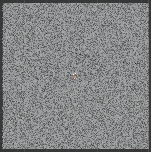
Why is is not possible to have some of those points disappear if they are too far away from the curve?
Without subdivisions it’s possible to delete the points after the fact but it does not feel like any gradient is happening at all:
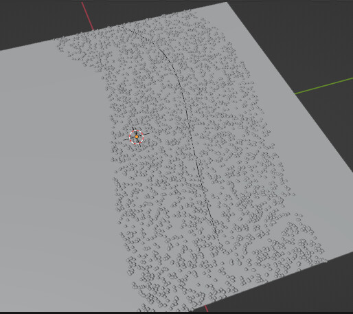
With subdivisions I can plug the Proximity value directly into Density of Distribute Points On Faces and after a lot of adjustments it almost feels like a little bit of a gradient might be happening.

GN proximity simplified case.blend (159.3 KB)
I think it’s probably because each face will return a different value, increasing the resolution of the gradient itself, no? Actually, I am just guessing here.
All of my previous comments are awaiting approval so I’ll try rephrasing.
I’m mostly going to be using this on geometry extracted from from legacy interactive digital entertainment products so there are going to be triangles and overlapping faces all over the place.
I don’t want to have to make new geometry or clean up old geometry.
I just want to extract some existing edges around a wall base to be the guide and a single geometry node network to the walls/floors which are separate objects in some areas and the same object in other areas.
The gradient from the proximity will be used both to put leaves on the ground but also to put a grunge accumulation map on both the ground and the lower portion of walls so I want proximity to the shared edge instead of the wall’s proximity to the floor and then the floor’s proximity to the wall (which is how your last file was set up)
I am not an expert in geometry nodes, but I think you can subdivide a mesh inside geometry nodes, right? I don’t think you really need to do anything. I just pointed out that you need more geometry, but if you use subdivision inside geometry nodes that may work. I never tried.
Edit: Yes, it works. You just need to put a subdivide mesh node right after the group input:

And since you are not joining that specific geometry anymore, those faces are virtual, I believe.
This plane had only one face.
Well, I did that just for me and forgot to put it back. I’m sorry for that.
As I said before, I’m not really good with geometry nodes, so I have no idea how to reproduce the effect of the shrinkwrap modifier inside there, so sometimes I would use a subdivision modifier and a shrinkwrap outside of geometry nodes to reproduce the surface to work with.
I set to use the edge again. It doesn’t really work as well as I’d like with geometry that is similar to where it will actually be used.
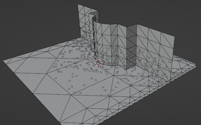
I’m going to continue exploring starting with high density points and then deleting points based on proximity to the curve. If I can delete 100% of points more than 1m away and 50% of points more than 0.5m away it should look good enough.
If necessary I’d rather apply the modifier and delete the leaves I don’t want instead of having to touch the original messy geometry.
Ah, from your earlier screenshot I made an assumption that you were somehow adding geometry at the edge of the floor/wall. It can be weighted easily - just by selecting edge loop and assigning weight.
But at any case, I had something a bit more procedural in mind.
You will have to mark something to tell the nodes where to work. Bottom edge of the wall seems like the most likely candidate. Either assigned to a vertex group or duplicated as a separate object, it can be used to generate some geometry with that “gradient” Attribute. And on that (purely “virtual” and then discarded) geo we can distribute the points. In theory.
GIF warning

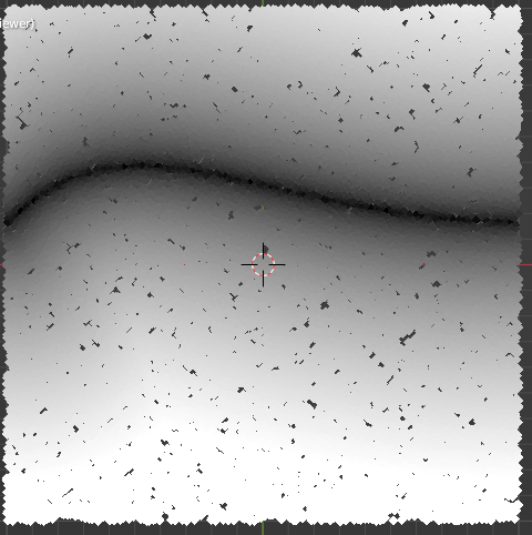
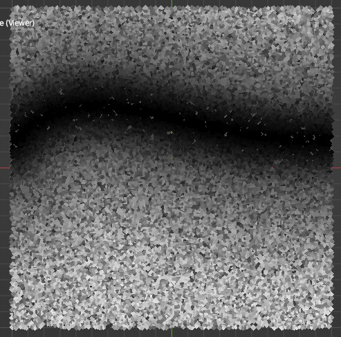
Points geometry plugged into viewer node and showing the Proximity Distance values.
The values shown are plugged into Selection of Delete Geometry.
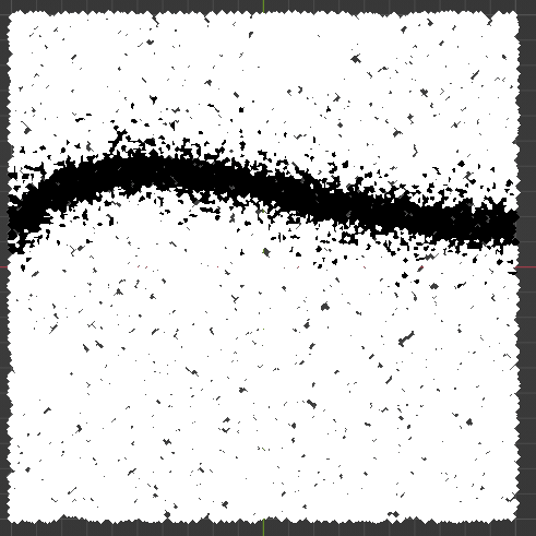
Everything greater than absolute zero gets deleted:
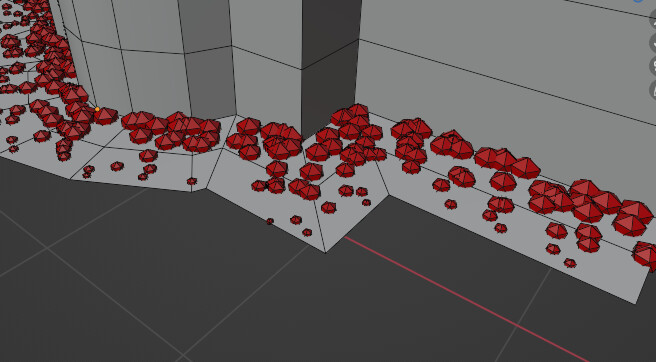
A voronoi texture applied to the points:
The 2 values Mix-Color-Multiplied together with some color ramp easing on both values before the combination:
All values Greater Than a certain value with tweaks made at the color mix factor and color ramps:

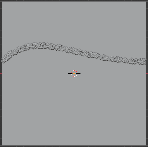
Now I just need to make it work as
- only a gradient for going up the wall and across the floor for mixing with materials
- only instances of leaves on the floor (this), but not also going up the wall. Can probably delete all points above a Z value.
Good solution but I’m trying to kill 6 birds with 1 stone.
- No manual labor making new geometry beyond duplicating some edges from an existing mesh where the walls meet the floor.
- Most of the original geometry is messy triangles with many duplicate verts and overlapping faces and faces inside of faces and 68 faces sharing the same 4 verts and 3 of those 4 verts shared with 18 other faces.
- Cleaning up the original geometry (deleting a single vert) often causes UV issues I don’t want to have to fix.
- Some parts of the floor are just the floor. Some parts are connected to the wall. Some parts of the wall are not connected to the wall next to it, or are a completely separate object or have a different material or all of the above.
- Adding new geometry just for the leaves won’t be able to participate in the material mixing I also want to do in the corners of wall/floor intersection.
- I want a gradient going out from the edge both up along the wall and on the floor to simulate dirt build up in the crevices. I will export that attribute to mix with the original image textures in the multiple floor and wall materials. This could be done with ambient occlusion node but whenever I add that to a scene it takes 5 - 10 minutes before cycles can render again (I use daily alpha builds).
The desired workflow is to
- select all walls and all floors,
- go into edit mode,
- select all/most edges where the walls meet the floors
- duplicate, separate by selection as new object
- Add 1 geometry node network to all wall and floor objects
Result:
- all floors have leaves built up in the corners.
- no walls have leaves stuck to them.
- all walls and floors have a “corner dirt” attribute that looks like a gradient that I can then mix with all materials used on floor and wall objects to make them look darker where the walls meet the floors.
I see… ![]() I have a feeling you’d need at least two stones for this task. If I understand correctly, Attributes are essentially the same as vertex colors - the gradients will only be as good and detailed as topology. If it’s an un-subdivided plane, there can only be a linear gradient between vertices. That’s why, as @Calandro pointed out, we need more subdivisions to get results.
I have a feeling you’d need at least two stones for this task. If I understand correctly, Attributes are essentially the same as vertex colors - the gradients will only be as good and detailed as topology. If it’s an un-subdivided plane, there can only be a linear gradient between vertices. That’s why, as @Calandro pointed out, we need more subdivisions to get results.
Depends on what kind of precision (or “realism”, or “quality”) you expect in the end, but it seems like a way to go is to solve distribution with geometry approach and shading with an actual AO.
Unless… “AO” gradient can be put on fake geometry, like some procedurally generated decal… hmmm ![]()
But then again, I might be completely wrong about this and there’s an elegant solution ![]()


