Threads (screw modifier) - not manifold, can't use boolean modifiers

This is related to, and sort of a follow-up to another question I posted about threads. This is a different set of issues, so it seems like it belongs in a separate thread (no pun intended).

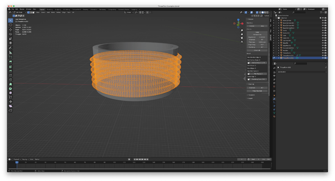
I have a 50mm cylinder (hollow in the middle) and a isosceles right triangle, 3mm high. I’m putting the triangle flush up against the outside of the cylinder and using a screw modifier on it, with the cylinder as the axis object. I’m trying to make threads to go on the outside of the cylinder, so I can use it as the male threaded part (eventually I’ll be doing this with a fitting for a conduit) and so it can screw into a female counterpart.

I can, if needed, attach the thread to the cylinder by using Join. I’ve tried it using a boolean modifier set to union, but I get a mess.

The blend file is attached. I also have a lot of pictures to show what I’m doing and where things go bad. I’m using the 3D Print Toolbox since my goal is to print out what I design in Blender. If you’re using my blend file, my parts are on the right side of the X axis and the pieces I’m experimenting with are on the left side. I move from the Y axis toward the left.

Step 1:
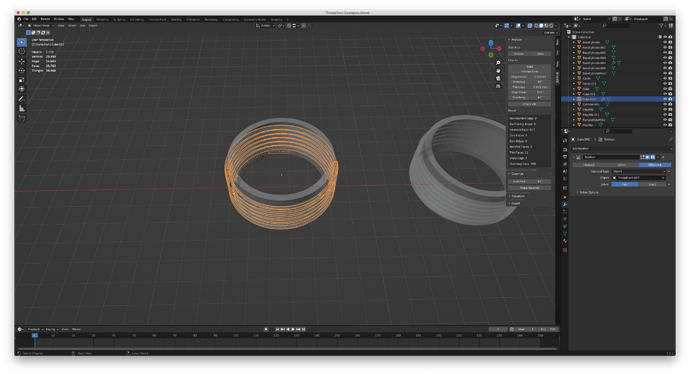
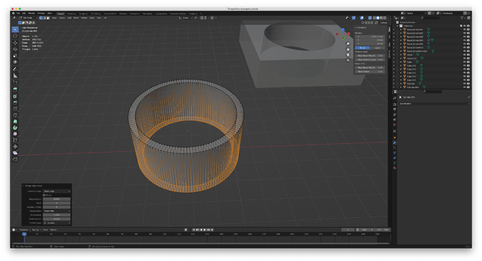
The 1st test object group, immediately to the left of the Y axis, has the cylinder and the triangle with the array modifier before I apply it. The next (moving to the left) objects are the cylinder and the thread after I apply the modifier to the triangle.


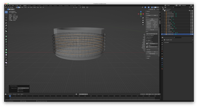
I used screw modifier, as described above, to make a thread going around the cylinder. This left all the normals on the faces of the thread pointing inward and I had to create a triangle face on each end of the thread, then I flipped all the normals. The triangle that’s the base for this thread is 3mm high and I set the screw height as 3mm. I ran the test and get a report of 1,179 intersecting faces. The stats show 2,307 vertices. Thinking that it might help to remove duplicates, I do that. It leaves me with 1,666 vertices, so it’s combined a number of them. The intersecting face issue is solved, but now I have 640 non manifold egdes. When I click the button in the report, it shows a line between each thread iteration as the non manifold edges.
I’ve done a number of experiments and it seems that as long as I make the thread distance in the screw modifier the same as the height of the plane I’m using, I run into this:

When I click on “Make Manifold,” the thread vanishes from the display.
Apparently, making threads the same height as the object I’m using to make the threads is an issue. There seems to be a need for a gap in there to prevent issues with overlapping edges and vertices.

First issue/question: Is this true? Is it necessary to make the screw distance greater than the object used as a base for that modifier, or is there some way to make it work if the distance in the modifier is the same as the height of the base object?

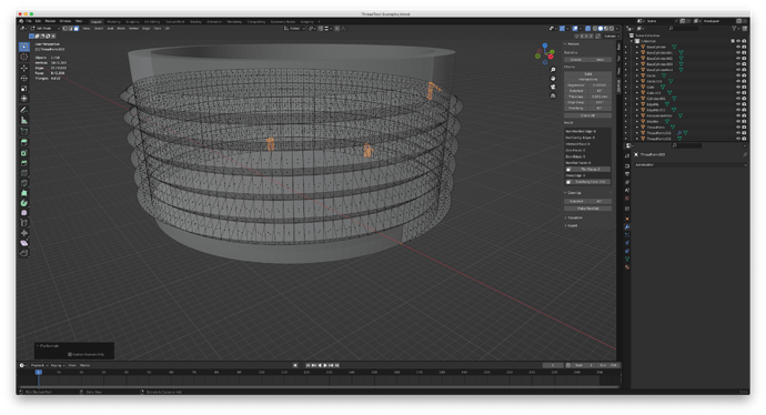
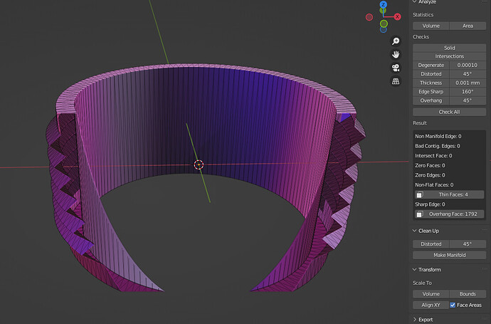
As a solution to this, I changed the thread distance to 3.1mm. When I do that, I get 3 thin faces. (Ignore the overhang faces. I know the angles and I’ve printed those before and they’re not a concern here.)


I’m not worried about the thin edges, since, again, looking at the angles, I don’t see why the printer would have an issue with them. So this time, with a bit of distance between each iteration of the thread, it seems to work out okay.

So far, so good…

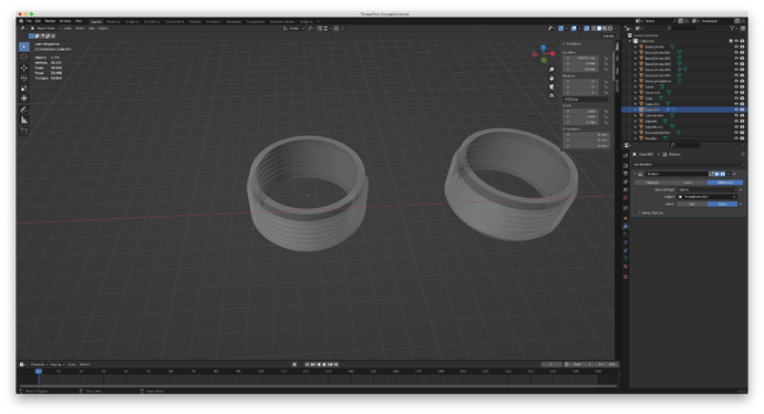
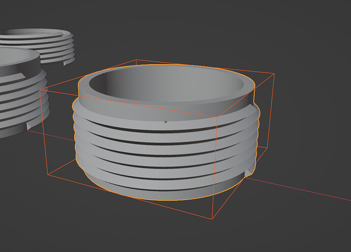
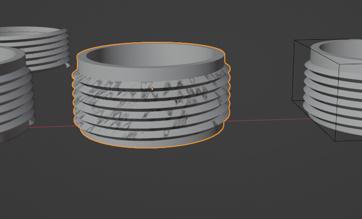
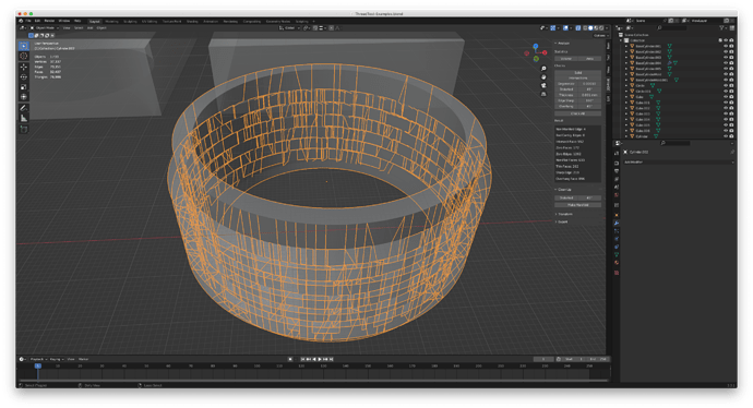
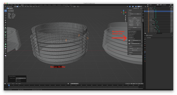
In the blend file, after those two objects (the cylinders and threads), there’s a gap, then three more cylinders, side by side, along the X axis and farther to the left on the Y axis. The first is the cylinder and the thread that’s a result of using the screw modifier. I tried to use a boolean modifier and union to join the threads to the cylinder. I’ve tried several ways and they all create objects that have issues. Just using the normal boolean modifier,


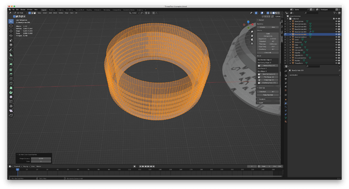
At first it looks okay, but on closer look there are what seem to be multiple overlapping faces and edges. There are also a lot of intersecting faces.

Move down to the next group of objects to the left and, to connect the threads to the cylinder, I used Join and it works. I might be misunderstanding things, but I thought I’ve seen people write that the boolean modifier works better. When I select the cylinder and then add a boolean modifier and add the thread as the object to use as a modifier, then use a boolean modifier and union, I see the threads disappear. Join seems to work, though.

So, using Join, I get the threads attached. It seems to work, but I don’t know what I did wrong with the boolean modifiers that they would not work with threads properly. (I tried them using both exact and fast matches.)

This leads to the next step, and next issue. Once I have the threads on the cylinder, I finally have a male connector that looks like threads on a pipe, which is the ultimate goal. I used a box that’s bigger than the male part and made a hole in the middle with a boolean modifier.

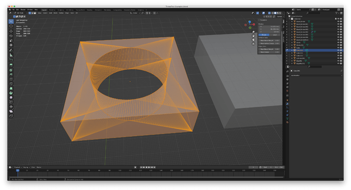
I take the square block I’m going to use for the female part and center it on the male cylinder with its threads. Then I click it, add a boolean modifier, and pick the male part as the modifier for it. The female block disappears:


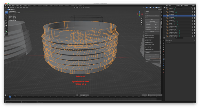
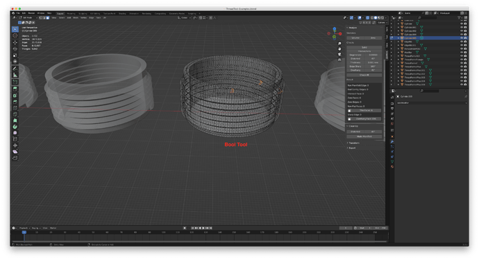
I experiment with exact and fast modifiers and when I use Alt-Z so I can see the wireframes, I get this - again, like the female part I now want to modify seems gone:

In those last 2 pictures, I have the boolean modifiers visible, but the big square part I’m using to make the female isn’t even visible.

Here’s what I’m finding I can’t do or that just doesn’t seem to work:

  1. I can’t use the same thread height as the object that’s the base for the thread - the height has to be more so there’s a gap. I don’t know if there’s a way to fix that.
  2. I can’t join the threads and the cylinder without ending up with problem edges or faces that show up in the 3D Print Tool Box. The boolean modifiers do not work well for this and I have to use Join.
  3. Once I get an object with the cylinder and the thread joined, when I put something around it to try to make a female counterpart to the cylinder and thread, the modifier does not work. The object disappears or I run into other problems. I’ve seen threads show up, but not visible - they are there but behind faces that surround the inner, empty circular hole.

In earlier tests, I’ve managed to get these steps working, but I don’t see how I can rely on boolean modifiers, which I need, to create the female counterpart threads and it seems like only Join will put threads and the cylinder together.

ThreadTest-Examples.blend (416.6 KB)
Just a quick reply…make sure to use Booltool…instead of the modifier…in this pic, the one to the Left is with a Ctrl+J…the Boolean was the cause of all the mess… the one on the Right is Booltool Brush Join…

In this pix…here is the second from left with the artifacts and the bool-modifier…


The modifier duplicates the thread so it looks as if z-fighting meshes…just Hide the newly created threads and all is well again…
image

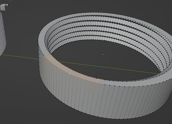
I did notice that for some reason on the original file ( other thread…), your ring with the threads was not a continuous loop…something happened in the modeling that broke the edge loop…not sure?


Deleting these 2 edges Top and bottom and then Bridge the edge loops fixes it…

It will play hell with booleans

Hey, anything that can get me moving in a better direction is appreciated!

Didn’t even know there was a Booltool - just SO much to learn in Blender. With the thread issue, I had found there was also a tool to make threads, but the modifier is easier, at least for me. Nice that various functions are duplicated so one can use what works best. There are just so many things under Add-ons that I haven’t had time to explore many of them.

It took me a while to learn about that. Since I learned how that works, it’s easy for me to ignore the original threads that the boolean used until I’m finished and can delete them or move the object out of the way. Sometimes it’s like seeing the interference pattern is a sign it worked.

I have that happen a lot when I make a cylinder and cut out the center with a boolean modifier. Sometimes I get a single face for the top circle, sometimes it’s 2-3 faces. It varies and I’ve wondered if that’s normal or a result of what I"m doing.

So, in this case, I’m figuring that’s one of the problems but not the only problem.

I’ve add the Bool tool and I’ll be working with that to see how it works for me later today.

I did more experimenting. Even using the Bool tool, I cannot get good results joining the thread to the cylinder. First, @RSEhlers , I took your advice about bridging the edge loops in the cylinder. I also did that with the square piece I’m currently using for the female threads. Here’s what I got when I deleted the edges and bridged the edge loops:


I realize that triangles or quads are preferred, but I’ve also seen times where having a single face instead of multiple n-gons seems to work better, but I also understand, now, that the n-gons in the top and bottom planes on these objects were creating problems. Lesson learned and I’ll be taking care of this in future work.

I created another thread, in the same way, using the screw modifier. I tried combining it with the cylinder with the Bool tool, but had the same results as with the boolean modifier. I got results like this:


So I used Join, again, to put the threads on the cylinder. (This time the newer cylinder, with all the quad faces for the top and bottom planes.) Then I checked it using the 3D Print Tools and found a problem with a number of intersecting faces:

I picked “Make Manifold” and it looked like it fixed it, then I looked at one side, where the thread starts and ends and saw a problem there. I performed the check again and still had a lot of intersecting faces:

So I am not yet producing a clean object that consists of the cylinder and the threads.

I did try using Bool tool to make the female threads and it didn’t work, but I don’t expect that to work until I can be sure I’m making a manifold object that doesn’t have all these problems.

I finally managed to find a way to create something that came out as a manifold object. I experimented with different forms for the screw modifier and using the boolean modifier, bool tool, and join to put the parts together. First, the threads. Here are the forms I made to use for threads.


I had been using #1 regularly and found that there were issues with the inside of the thread and the outside of the cylinder, with faces of one overlapping or interfering with the faces of the other. So I tried #2, just using a greater than sign. That was better, but when the thread was constructed with the screw modifier, it had no inside surface, which created a lot of problems.

I added an extra area with the idea it would go inside the cylinder. That would mean not having surfaces from the cylinder and the thread overlapping each other. Ultimately I found success with #4, the enclosed shape that looks like a baseball home plate or a simple house sketch turned sideways. I put the left edge and the horizontal lines on the left into the cylinder, so the vertex between the bottom horizontal line and the diagonal line was right at the edge of the cylinder. (See image below)


When I turned this into a thread, then added a face on each end of the thread, then flipped the normals, I had a manifold object that overlapped the cylinder.

Then I tried connecting the result to the cylinder with three methods: Boolean Modifier, Bool Tool, and Join. After joining them, I merged duplicates by distance. (Interesting how the number of vertices varied from one method to the next.)

Here’s the result with the Boolean Modifier:


(I’ll note that before I merged by distance, I had more issues, but they vanished once I did the merge.)
The only issue here is thin faces. For this object, I’m not worried about the reported thin faces, since, when you examine them, they’re not an issue. Overhangs are not an issue, since I’ve found I can print these threads without overhang issues.

Here’s the Bool Tool result:


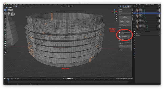
When I merged them, I had hit Alt-Z so I could see all the vertices. In Object Mode, with Alt-Z, it looks sloppy, but when I checked it out with the Print Tool Box, here’s the result:

The Intersecting Faces item is selected here, but note there are a number of other issues. Often, with these tests, when I click “Make Manifold,” it creates some exotic result I don’t want, but I did that here, with this result, and it gave me this:

Note it gives me the same 6 thin faces that I get with the Boolean Modifier. (What puzzles me is why only these 3 faces show as thin when all the faces on the thread should be uniform.)

Here’s the Join result:


A lot of intersecting faces, even after I click Make Manifold. (I don’t remember if this is the shot before or after I cleaned it up with Make Manifold, but the numbers weren’t very different.) Also, it may be hard to see, but in the boolean methods (both of them), the part of the thread that protruded into the cylinder was absorbed by the cylinder. That’s not the case with the Join command, which leaves a messier mesh. (And may be part of the reason for the issues that show up.)

Conclusion: Both boolean methods (modifier and tool) worked and gave me the same results. Also, when making a thread to attach to an object, it seems to be a good idea to use an actual face, not just a few edges forming an open shape. In this case, it worked much better when the form for the screw modifier could penetrate into the thread object it will be joined to.

If any of this is wrong, please correct me and clarify!

ThreadTest-Examples.blend (681.0 KB)

Yeah, the thin face issue is a mystry…it is actuall in some cases a duplicat face over a face that is triangulated ( from the boolean as far as I could tell be fixing it…dileating the faces and adding new, merge by distance …and check make non-manifold and more thin faces etc etc…

Best I could do was a Plain Boolean Merge…and fix the issues…there were a lot of Non-Flat faces…which don’t make sense ( how ? when it is a standard cylinder? ) But I didn’t check if the screw was equal with the cylinder divisions? Also it depends on which order you select for the boolean…click screw then cylinder or vise-versa…
best I could do…

I went ahead and triangulated the mesh as it won’t make a difference on a STL/print nether are the thin gfaces as you set that in your printer prefs …

The only thing I don’t like is the beginning and end of the thread it should taper of towards the top and bottom till only a small sliver is around the top/bottom edge loop…
Ill look later and see what I can come up with…
ThreadTest-Examples (RSE).blend (915.9 KB)

PS: Reset the clipping distance…I just wanted to see a cross section…

What confuses me is that the thread is uniform, from start to end, excluding the start and end, and that’s where I’d expect exceptions, so when I get thin faces or anything else on a dozen or fewer points along the thread, it seems peculiar.

I’ve had some non-flat faces, but they were either too many to bother to fix if Make Manifold didn’t fix them or they were right around the start and the end of the thread.

Yes, that’s a critical part of the process. I’m now using a thread form that’s 3mm high, but in the screw modifier I give it a height of 3.1. If I make that height the same as the thread form, then I ALWAYS get problems where one iteration joins the next. Merging doesn’t stop that. I could probably reduce it to 3.05 and get good results. I’m going to try that.

Oh - yeah, that’s an excellent point and may explain those issues where something like 7 sides are thin. It might just be where the divisions of the thread and cylinder don’t line up. I’m using PrusaSlicer and, for now, a Prusa for printing. (I have an Ender 3 Pro, but that’s been a nightmare to get up and running.) PrusaSlicer has absolutely no problem with the thin edges or faces that show up with this particular project. (I know that PS can detect that as an issue, so it’s not due to lack of ability…)

I’m using 128 for the cylinder divisions and the threads. That seems to be about where it looks and prints as a circle.

Yes, I’m finding similar issues. I’m having to make sure I do things just right and if I do, it’s like magic. If not, it’s a mess. I did finish getting a good male thread and female counterpart, then made copies of the female at 102% and 105% scale (XY only - Z is static). The 105% works fine, but is too loose. Sadly, this was late at night and I was exhausted, so I didn’t write up my exact sequence, but I think I can duplicate it today. I’m going to try 103% and 104% to find which one works with a tight fit. Right now, I’m happy I got it working in Blender and thrilled I have printed “proof of concept” parts that are working. True, this is only on a 50mm or roughly 2" pipe and I need 100mm for the final project, but now I know I can do it. (Even though I live in the US, I find that whenever I can use metric, it’s much easier than imperial measurements. I had downloaded an item someone did at 100mm and it worked fine with the 4" flexible conduit I’ll be using.)

Yes, and that’s part of what I’m doing long range. I forgot about it in the tests I did last night, but they worked. What I do is add the thread to the pipe, then use a boolean with a big block as a modifier to cut off enough of the bottom that the thread starts as you describe. The “top” end of the thread will go into the surface of the connector it’s on when I do the final project.

1 Like

For those following this thread in the future, one other tip I’ve discovered that has made a big difference:

To get the threads to start smoothly, as we discussed earlier, they should start as a wedge. I’ve used boolean modifiers to lop off the very top and bottom of threads. I found if I made the thread, made sure it was manifold, then did a Boolean union with the cylinder and, after that, cut off the top and bottom of the threads (so they’d start as thin wedges), I always ended up with issues with the result being manifold.

When I changed the order, and trimmed or lopped off the top and bottom of the threads, THEN did a Boolean union with the cylinder, I didn’t have issues.