Traced Textures: A method for vector based resolution independent continously rasterized textures

I couldn’t find any tutorial on the subject so i decided to make my own. Any suggestions welcome.
Sorry for the lengthy title but sincerelly there is no better way to describe it.
And sorry for the failed previous attempt to start this topic.


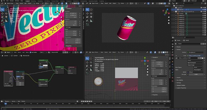
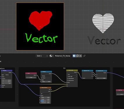
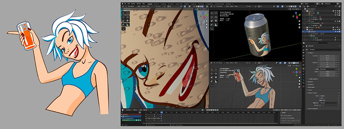
Left: Inkscape Illustration. Right: SVG file imported, animated an applied as texture in Blender

The subject is rather versatile and the uses and options are huge so I will try to stick with the basics and expand in future posts.

Also, I think this method is software agnostic (even if Blender is my favorite choice), so if you have the opportunity to test it in other enviroments, just let me know.

00 PURPOSE

This method’s main usage is the creation, modification and animation of textures from within Blender.

If we want to use lineart as textures in our 3d models, we wont’t have to convert our designs to raster images. Just import and use them.

Also this method puts an end to the endless going back and forth when our designs are subject to revision or the animated texture changes and we need to export or render over and over again.

Another advantage of this method is that the textures are calculated on the fly and are resolution independent in a similar way to what in other applications is called continuous rasterization.

Hope it is useful for your projects, so let’s get into it

01 THE BASICS

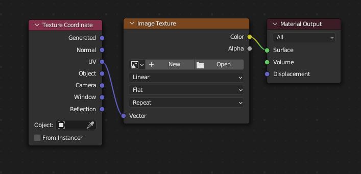
The standard way the render engine checks which texture is in an object surface is by linking (mapping) the pixel coordinates of an Image Texture with the Texture Coordinates of the surface. Then, for every Texture Coordinate there is a color parsed from the Image file.


The most basic texture setup.

The Traced Texture method is based on substituting the bitmap image coordinates by 3D World coordinates mapping them with Texture Coordinates.
Being the two spaces defined in float numbers, the first effect will be that the texture generated keeps its sharpness no matter the zoom or the resolution.

Also, being generated from within Blender, we can create designs, modify and animate them on-site, and the Traced Texture is updated continuosly without the need of pre-rendering.

We can know the contents of a 3D coordinate by the use of the function trace in OSL language. So yes, we have to script, and no, we don’t need expensive hardware.

The function trace ( Origin, Direction ) --No options for this basics— sends a ray in the scene from the Origin point in the direction of the Direction vector.
If the ray hits a mesh, the function returns 1.
If the ray misses, the function returns 0.

If we put this function instead of the Image Texture node above, feeding the Origin with Texture Coordinates (as if they were the plane XY from wich the rays depart) and set a vector pointing downwards (0,0,-1) as Direction, we can trace the contents of a box contained in the 1x1 XY plane and down.

The basic procedure is as follows:

Place the objects to create the texture in the unit XY area. Keep them below Z=0 to avoid possible clipping errors. Any mesh object will be trace, be sure to fill your splines to be seen. And any mesh also can be a particle system, a metaball a fluid…

Aside will be our textured object. The object needs to be properly UV unwrapped or use Object coordinates to avoid distortion.

To use OSL we have to set the render settings acordingly: CPU and check Open Shading Language. Reduce your carbon footprint until OSL for GPU arrives.
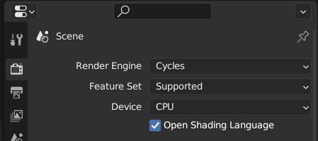
023_Render Settings OSL

Open the Text Editor, create a new text, name it eg. “Tracer.osl” and write:

shader Tracer(
       vector Origin = 0,
       vector Direction = 0,
       output float Mask = 0
)
{
       Mask=trace(Origin,Direction);
}

The shader is pretty self explanatory.

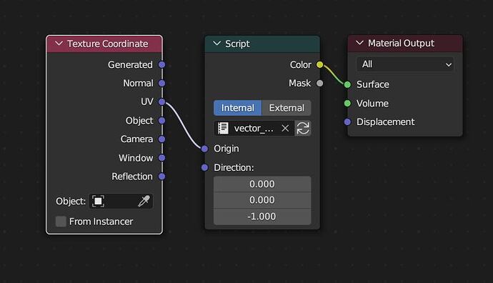
In the Material Editor add a Script node, load your Internal written shader, plug UV to origin and set Direction to (0,0,-1).
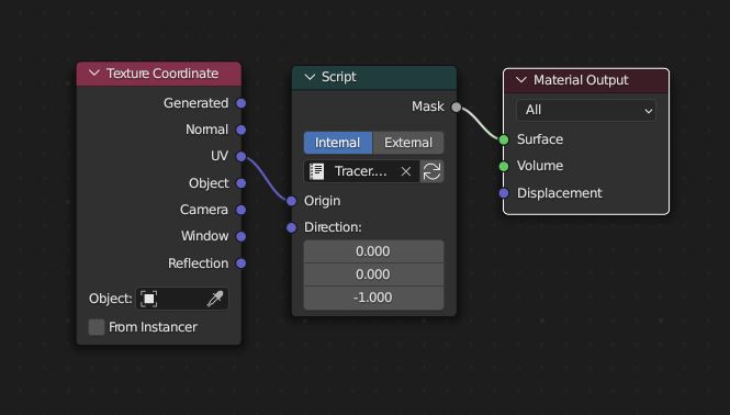
025_Basic Node Mask Setup

We have substituted the Image Texture by a Traced Texture. Set the View to rendered and watch the results.

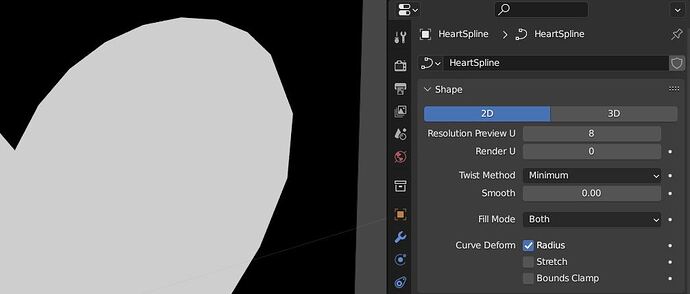
If we zoom, we see that the texture mantains its sharpness, maybe the poligonal edge contour is noticed but increasing the Resolution of the curve fixes the issue.

More to come, the trace function not only gives us hit data, it collects data from the hit mesh and it is delivered through the getmessage function:

getmessage(“trace”, “object:color”, Color)

reads the object:color data of the object hitted by the last trace call and assigns the value to the Color variable. This color is not the color of the object material, is the Viewport Display>Color in the Object settings panel.

Our extended shader:

shader Tracer(
       vector Origin = 0,
       vector Direction = 0,
       output color Color = 0,
       output float Mask = 0
)
{
       Mask=trace(Origin,Direction);
       getmessage("trace","object:color",Color);
}

The shader in use:

Want more? play with:

getmessage(“trace”,“object:index”, Object_Id)
Returns the value (per object) in Object Properties>Relations>Pass Index into the Object_Id (float) variable.

getmessage(“trace”,“material:index”, Mat_Id)
Returns the value (per material) in Material Properties>Settings>Pass Index into the Mat_Id (float) variable.

With Converter>Math>Compare we can separate de results in different masks.

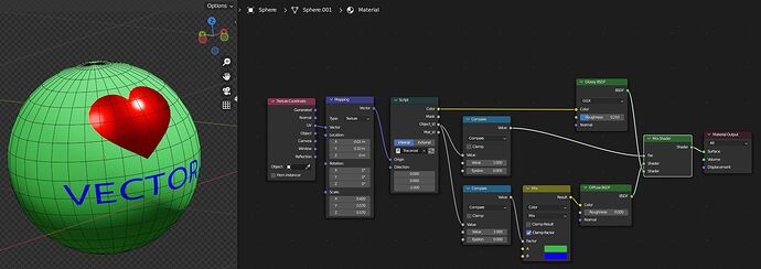
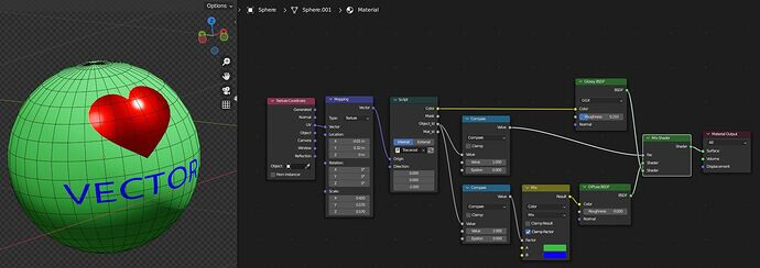
A crazy useless setup with Object Index: The heart’s Pass Index is 1 y and text’s is 2.
The compare nodes split the Object_Id output allowing the heart to have a glossy surface keeping its Object Color and the text to act as factor mask in the blue-green color mix.

The basics end here.
Next chapter: Scene management and troubleshooting.
10 Likes

02 SCENE MANAGEMENT AND TROUBLESHOOTING

We have turned a fragment of 3D space into a “window” to Trace Textures, any object crossing it will appear in the texture and maybe this is not what we want.

The plane enters the 1-unit XY area and traces itself in the texture.

OSL trace function suggests a traceset option, wich would define a group of objects to trace (or not) but it is not implemented in Blender Cycles.

The simplest solution to this issue is keeping the tracing area away from our main action.

Parent the objects to be traced to an Empty, which will become the Root of a “mini-scene”.
Then move away the Empty (with all the group) to a separate or hidden place.

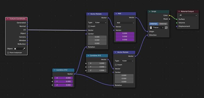
In the Material Editor, move the trace Origin, adding with Vector Math the position of the “mini-scene” Root position.

Be careful not sending the objects too far. At high numbers the tracer starts to fail due to math precision.

Detail of the texture. Left: mini-scene at 10m Right: mini-scene at 10000m

You can also rotate the “mini-scene”, useful if we want to trace simulations, fluids or dynamics affected by gravity.

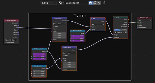
To compensate the rotation for the tracer, add a Vector Rotate node to modify both the Origin and the Direction vector.

In the example setup, the rotation and the position of the “mini-scene” Root Empty is copied here by drivers.

As with any texture, we can add transformations and effects (tiling, distortion, noise blur…) but remember: Nothing between this “mini scene” transformation nodes and the Script node.

Scene management and troubleshooting ends here.

Next chapter: SVG workflow.

Play with it, improve it, share it.

Enough for today. Stay tuned.

10 Likes

Really interesting bro.

1 Like

Damn, this is amazingly clever !
You did a really good job in explaining all that ! Even if it took me a bit of time to be really sure of what you were doing since it’s quite mind bending !

If I understand correctly, to get the gradient on the heart example :
image
You have in fact as many object as gradient’s steps, since it uses the ObColor to retrieve that info ?

Thanks for sharing and I hope people in need of that will find their way to that page !

2 Likes

Thank you!

The object:index and material:index is a way to do an Object Pass and Material Pass with our tracer.
Think of it as a kind of Cryptomatte where the masks are selected by number. The values can be wathever you assign: Heart can be 3 and Text can be 9, for example.

Maybe i went too quickly to the point. I’m changing the intro to reflect better the purpose of all this.

Again, thank you!

2 Likes

Interesting. May stimulate me to learn OSL someday.
Can OSL trace outpit a “picture” with shading to use further in the pipeline? Like Render to Texture/Render Target effect in game engines, which lets you use render result of additional camera in a shader?

Ok thanks ! I think I was a bit confused by the pictures, the white spots in the heart are actual specular reflections, I thought it was part of the SVG, hence my question !

I’m a bit tired and it may not be the appropriate time to ding into technical stuff like that !

Looking forward to the next posts ! I really like these kind of techniques !

Yes, but with some limitations. You cannot shade with OSL but can implement your own simple shader with the tracer.

A chapter about Perspective projection (useful for CCTV faking) is on the way, but first I want to cover more general usage issues.

Thank you.

1 Like

That’s promising, because I do not seem to be able to find any script reference online to see what it can or cannot do. Like, how to output position or normal of an object hit. I will have to rely on you in that regard

You can try this while you wait :wink:

getmessage (“trace”, “N”, Normal);
getmessage (“trace”, “P”, Position);

N and P are global variables in OSL (no need to declare them)

2 Likes

Cool, thanks. And a final question: can it be used to generate a distance field from a trace target to an object carrying the shader? I imagine that would require storing all the results of the trace in an array or picture, then looping through it to find what is closest to given surface point, but I do not understand programming very well. Sorry if it is stupid

Will also require a way to mask the shader object from a trace, so yeah, thats the stupid idea(

Play around while I work on it. Be patient.

2 Likes

03_GENERAL SVG WORKFLOW

Now we can do all of our vector and animated texture bussiness inside of Blender, but also we would like to import our lineart from a vectorial design software, keeeping all of its quality.

The standard SVG file import module has some limitations we should be aware of when preparing the lineart prior to Blender import (workarounds following are related to Inkscape):

  • Only solid fills, you will have to reproduce the gradients using the Material Editor in Blender (good chance to use the object:index or material:index with the Tracer). You can replace them with solid fills in Inkscape.
  • No blending modes (again they have to be done in the Material Editor)
  • No swatches (Edit>Select Same>Fill and click on Flat Color in the Fill Properties) Don’t worry, they are replaceable with materials, more on that later.
  • No text (Path>Object to Path)
  • No line styles (Path>Stroke to Path)

The SVG document units are translated straight into Blender, a document 1000x1000mm and Scale 1 mm per unit in Inkscape will be 1x1m in Blender.

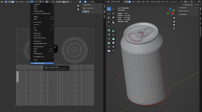
If the object on wich we plan to apply the traced texture is UV unwrapped, it is a good idea to save an image of the layout (UV Editor UV Menu>Export UV Layout) to use it as guide in Inkscape.


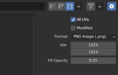
051B_Export UV Layout Settings

Take care with the export settings, unchecking All UVs will only export the layout with the selected elements.

Above: Arrangement of the design with the exported UV Layout in Inkscape.

And inversely, if we don’t want to modify the original arrangement of the SVG design, it is a good idea to export a bitmap from Inkscape to use it as background for the UV editor in Blender.

Anyway, take care to work always with square images and documents if you want to avoid headaches with proportions and non uniform scaling.
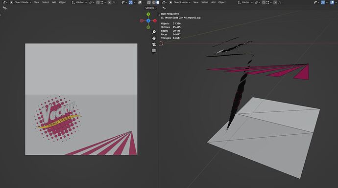
In the imported SVG file into Blender, the lower left corner of the document is at the 3D world origin and the objects are placed at the positive XY quadrant. That is what we want to generate the Traced Textures.

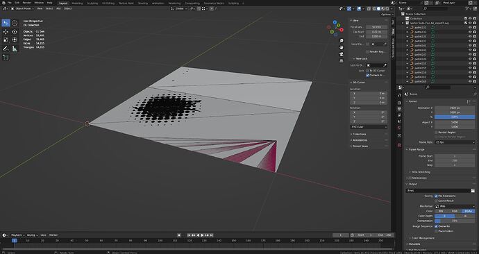
But all of the shapes are stacked Zfighting at Z=0, and the object color is not the color of the SVG fill set in Inkscape.

We have to distribute objects in Z following their stacking order, almost impossible even if the shapes are few. A simple python script will help us.

Let’s say we want to distribute the selection along 1 unit up starting from z=-1 (zpos), we divide the distance between the number of selected objects (zdiv) and go adding that number (zoffset)to the z coordinate (obj.location [2]) starting from z=-1. It allows much improvement but it will work.

import bpy

select = bpy.context.selected_objects
zdiv = len(select)
zpos = -1
zoffset = 1/zdiv

for obj in select:
    obj.location[2] = zpos
    zpos += zoffset

Select the objects to distribute (Rick-click the SVG Collection in the Outliner and >Select Objects to select the full design) and click on the play arrow button in the text editor to run the script.

The SVG importer keeps the stack order in the Outliner so the selected objects will be correctly distributed in Z. Switch the Top view to Orthogonal (Numpad 5) to not be confused by perspective.

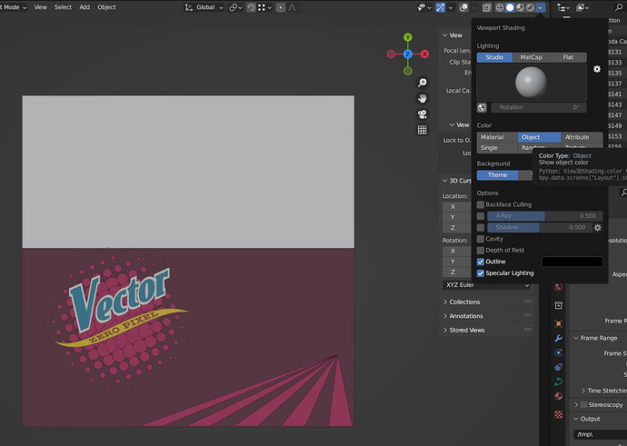
To change the color our advantage is in a flaw of the SVG importer: as a heritage from Blender Internal days, the nodeless materials created for the shapes are made of a lonely diffuse color.

This issue makes really easy the use of a python script for the transfer of diffuse to color.

import bpy

select = bpy.context.selected_objects
for obj in select:
        if obj.active_material != None:
            obj.color = obj.active_material.diffuse_color

Click on the play script button and change to Color>Object in Viewport Shading menu to see the changes.

From this moment fully enjoy the use of Traced Textures in the scene.

Want more control over the imported SVG file?

The SVG importer created a different material for every shape of the original file.

With python (again) we can check equal materials to remove duplicates and recover the swatch functionality we had in Inkscape.

import bpy

select = bpy.context.selected_objects
MatList = []
for obj in select: 
        if obj.active_material != None:
            CurrentMat = obj.active_material
            obj.color = CurrentMat.diffuse_color
            MatList.append(CurrentMat)
            for Mat in MatList:
                if Mat.diffuse_color[0] == CurrentMat.diffuse_color[0]:
                    if Mat.diffuse_color[1] == CurrentMat.diffuse_color[1]:
                        if Mat.diffuse_color[2] == CurrentMat.diffuse_color[2]:
                            obj.active_material = Mat
                            break
bpy.ops.outliner.orphans_purge(do_local_ids=True, do_linked_ids=False, do_recursive=False)

This last script not only copies material diffuse to object color, it creates a material list and for every selected object if its material is equal to a higher material in the list, it’s replaced by the higher one, leaving a bunch of orphaned materials to be deleted by the purge command.

It will purge the full Blender file, if you want to control manually the deletion of orphan data, comment out or delete the last line of the script.

To use the simplified materials as Inkscape swatches, change to Color>Material in Viewport Shading menu on the viewport you are watching the SVG to interactively change colors by changing the material diffuse.
Run the script again everytime you make material changes to see them in the Traced texture.

The texture is not exactly as we want? No need to exit Blender to fix it.

And why not an animation?

Play with it, improve it, share it.

Next Chapter: Transforms, Effects and Nodetree arrangement.

5 Likes

Before going on to the next section, I´d like to share a quick tip.

As seen above, we are able to interactively adjust the traced objects on the textured surface, but there is the possibility of further control: placing a UV layout over the mini-scene with Geometry Nodes.

First make a linked copy (Alt+D) of your textured object, and reset its transformations (Alt+G,Alt+R,Alt+S).

Create a New Geometry Nodes tree for that linked copy:

To get the UVs unfold, use the “UVMap” (the name of your UV data) Named Attribute to feed the Position of a Set Position node.

Before this operation the faces of the mesh must be fragmented. Do it with a Split Edges node or a Duplicate Elements>Face node (any of those will do).

At the end place a Delete Geometry>Only Faces node to be able to see only the wireframe of the UV layout (this also avoids tracing it in the texture).

If we parent this modified linked copy to the origin of the mini-scene we have a direct reference of the UV over the traced objects. It will move and rotate with the mini-scene.

Just turn it on/off in the Outliner to change its visibility.

The basic idea of this tip came after watching “Transforming mesh to its UV map with Geometry Nodes in Blender” by Nikita Akimov and “Unwrap Your UVs in a Flash with Blender’s Geometry Nodes” by Johnny Matthews.
So credit and thanks for them.

3 Likes

04 TRANSFORMATIONS, EFFECTS AND NODETREE ARRANGEMENT.

To this point, he have fitted the lineart to the UV unwrapped setup.

In a standard texture setup, the Image Texture is exchanged by a script that traces continuously a subset of objects in the scene (the mini-scene).

We may want to use the lineart as a pattern or decal, escaping from the restrictions of the UV map. In that case we will add transformations in the nodetree and setups to modify the traced texture beyond a simple number-to-number transfer from the Texture Coordinate to the tracer.

Anyway there is a block in the nodetree that doesn’t chage: the nodes to compensate the position and rotation of the mini-scene and the Script.

We can frame them into a Tracer section (no grouping yet, some changes ahead):

Before this frame will be the transformations and effects.

GEOMETRIC TRANSFORMATIONS: POSITION, ROTATION, SCALE.

It is a good thing to differentiate between the objects we want to trace and the tracing area.

If we want to move, rotate and scale the contents of the texture (what is traced) it will be easier to edit and modify directly the objects in the mini-scene and not the Texture Coordinates in the Material Editor.

As a recomendation, the purpose of transformations in the Material Editor is to adjust the traced texture onto the object´s surface.

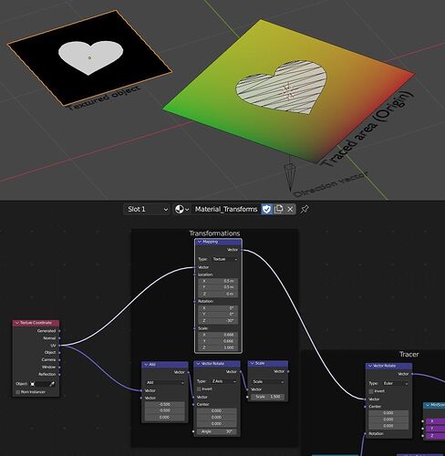
Being said that, the transformation of traced textures is done like in Image Textures.

Modify the position with Vector Math>Add/Subtract.

Modify the rotation with Vector Rotate>ZAxis.

Modify the scale with Vector Math>Scale or Vector Math> Multiply.

But be careful: we are transforming the Origin vector of the tracer. In fact, the area in wich the tracing rays are generated, the “window” to see the mini-scene.

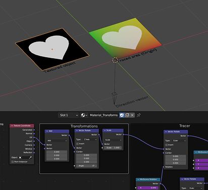
Up: Initial setup without transformations. A UV colored plane is overlayed onto the mini-scene for better visualization of the concept.

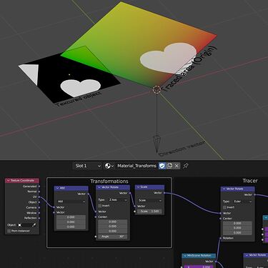
If the rays are originally traced from the unit XY area, if we scale that area we are shinking or enlarging the window. An scale of 2 doubles the size, and the objects in the texture are seen at half size.

Up: The window rotates and scales around the coordinate origin of the mini-scene.

If we can move the tracing window, there is no reason to have the mini-scene objects in the positive part of the XY plane, the mini-scene can be centered to its origin and it will make things easier when working with the texture in the Material Editor.

If the input from Texture Coordinate is UV, we move the UV center (0.5,0.5) to the coordinate origin.
If the input is Object, the move won’t be needed: the texture is aligned with the object origin.

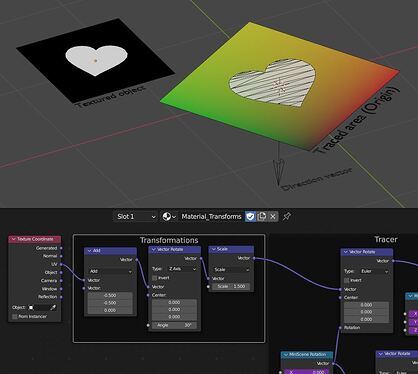
Up: The objects of the mini-scene are centered to the mini-scene origin (empty). With UV as input, 0.5 is subtracted from X and Y. Now the texture rotates and scales around the center.

Visually, the transformations are in the textures inverse to the tracing window transformation.

If we don’t like that behavior, the transformations can be substituted for a Mapping node in Texture mode, it will do the inverse for us.

Up: Two different ways of doing the same transformation.

CROP AND TILE

Working with decals, since we are modifying the tracing window, if we reduce the size of the decal (and the mini-scene is not away enough) we find that some elements of the scene start to appear in the texture.

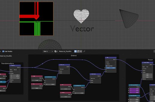
The easiest way to crop the tracing area is with Vector Math>Minimum and Vector Math>Maximum, which limit the Origin vector values.

The result is not exactly a crop but like the “Extend” mode in a Bitmap Texture node: if an object crosses the crop line it will “bleed” to the texture end.

While the limit values are within an empty area the result will be a crop (we are extending nothing).

The Minimum/Maximum method can be useful if our lineart has a flat background and we want it to extend through all the surface. Placing a background object in the mini-scene, that object´s colour will fill all the texture.

A mix node can be used to turn the effect on and off.

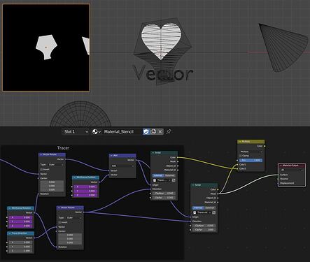
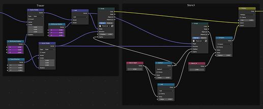
That is a quick method to limit the tracing area, but there is a more versatile way to clip the texture: using a traced object as clipping mask or stencil.

We need a tracer for the texture and a tracer for the stencil, placed at a different depth in the mini-scene for easy adjustment.

All the elements are traced at once just because the trace function fires rays to infinite by default.
Time to introduce two new fuctions in the trace function:

“mindist” defines the distance from the origin the rays are generated at. If not specified is zero. We can assign the desired value to a NearClip float input in the shader script.

“maxdist” is the travel limit of the rays, ignoring anything beyond. If not specified is infinite. A FarClip float input in the script can be used to specify it.

With this two options we mark two clipping planes for the tracer and the overlaying of stencils in the mini-scene can be managed.

The trace function take the form:
trace ( Origin, Direction, “mindist”, NearClip, “maxdist”, FarClip)

This is the modified OSL Script.

shader Tracer(
    vector Origin = 0,
    vector Direction = 0,
    float ClipNear = 0,
    float ClipFar = 1,
    output color Color = 0,
    output float Mask = 0,
    output float Object_Id = 0,
    output float Material_Id = 0
    )
{       Mask = trace(Origin, Direction, "mindist", ClipNear, "maxdist", ClipFar);
        getmessage ("trace", "object:color", Color);
        getmessage ("trace", "object:index", Object_Id);
        getmessage ("trace", "material:index", Material_Id);
}

Thanks to the clipping planes we limit the trace at different depths, but we still can see “intruder” objects if they are at the same depth as the stencil.

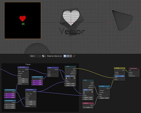
In this case we can refine the result, filtering it through the ObjectId output (the stencil object has a unique Pass Index value assigned in the Object properties panel).

A Mix node (Multiply) is used to activate or deactivate the clipping changing the factor from 0 to 1.

Indicating only the stencil object depth and a margin distance, the nodetree can be simplified for easy adjustment:

NOTICE that in the examples above we are blackening the areas outside the clipping in the Color output, apply this process to the mask if you want a transparent result in the cutouts.

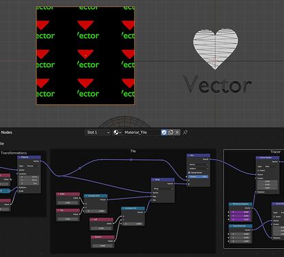
Tiling

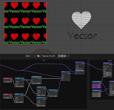
While Minimum/Maximum extend the texture beyond the limits, the Vector Math>Wrap operator repeats in a tile the values between the Max an Min values.

If instead of independent limits on the four sides we consider the decal as symmetric, with the proper arrangement only the X and Y spacing of the pattern is needed.

Again, the effect is controlled by a Mix node.

4 Likes

This became a rather lengthy post, so I splitted it.

04 TRANSFORMATIONS, EFFECTS AND NODETREE ARRANGEMENT (Continued).

EFFECTS

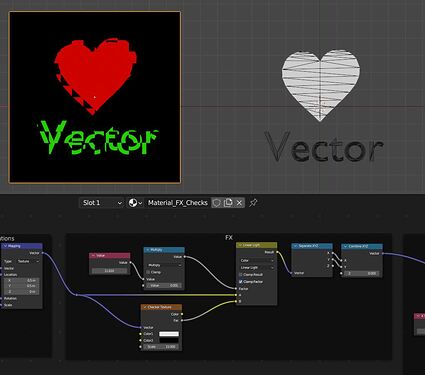
Altering the Origin vector with distortions and math operations, some effects can be applied like with Bitmap Textures.

We need to keep safe the Z vector component to avoid the tracing rays to depart from places not in the Z=0 plane. Separate the distorted vector components and combine only X and Y.

Distort

When using procedural textures to distort the Origin vector, a Mix node in Linear Light mode is the best way to control the effect intensity.

Distortion with Checker Texture

Distortion with Noise Texture

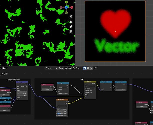
Blur

A Noise Texture with high Scale value gives a blur effect in a distance. But notice the distortion detail with a deep zoom.

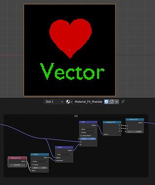
Pixelate

Traced Textures give us crisp clean designs, but we may want to pixelate them ( maybe in-scene animated pixel art?).

With the Vector Math>Snap operator we obtain a pixelate effect. Control the intensity with a Mix node in Vector mode.

NODETREE ARRANGEMENT

At this point, the nodetree is quite complex, and its time for tiding up. Lets create the groups and assets that will allow the use of Traced Textures from any scene.

First, a group “Tracer Script” containing only the Script node. This will put it at hand and is a general tip for reusing OSL scripts.

And a group “Tracer Basic” with the basic mini-scene tracer arrangement, enough to work when our mini-scene is directly in relation with a UV based artwork layout.

Notice that the Direction vector is always pointing to negative Z, so no need to input that value to the group.

When using decals, a group with possibly all the options above plus Transformations and Effects.

Choose which to include at your convenience, just remember the order scheme as follows:
Texture Coordinates>Texture Mapping>FX>Tiling>Tile Mapping>Extend>Tracer (including mini-scene transformations)>Stencil>Material Output.

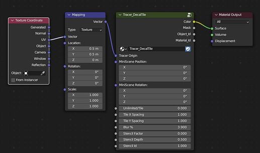
As an example: A group “Tracer_DecalTile” with only a Blur effect, we have discarded Extend on behalf of Stencil use, with input fields for depth and ObjectId.

Here is a .blend file for you to play.

001_Traced Textures.blend (157.2 KB)

To this point we have seen the main techniques for a use of Traced Textures aimed at creation of textures with lineart designs and animations.

The next chapter is about another use of Traced Textures: Perspective projection and Shading.

Experiment, improve and spread the knowledge. Any comments welcome.

5 Likes

Wow, this is cool, raytracing from OSL what a cool way to do it,

I can think of a few uses for this.

Awesome.

Really amazing thing !!! :smiley:

Thanks for the share and happy blending ! :slight_smile:

The idea came as a workaround to have AE-like continous rasterization in Blender.
Then I realized I could animate textures without pre-render.
Then… well It just grew to some kind of complex subject at the end!

4 Likes