This has been surprisingly difficult for me to approach, and it is showing the cracks in my modeling abilities. I have been learning Blender since 2008 (I go by the date of this BA account, ha), but I’ve never dived deep into hard surface modeling because the precision and intricate cutting and details have seemed daunting to me. I wish to overcome this by making this project, but I’m having trouble determining how to begin.
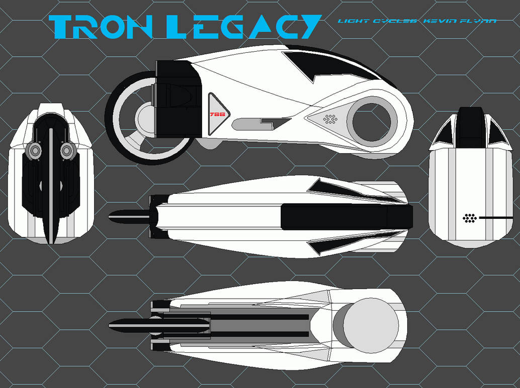
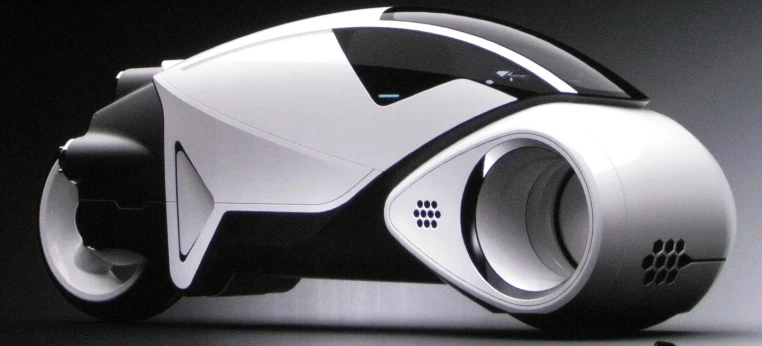
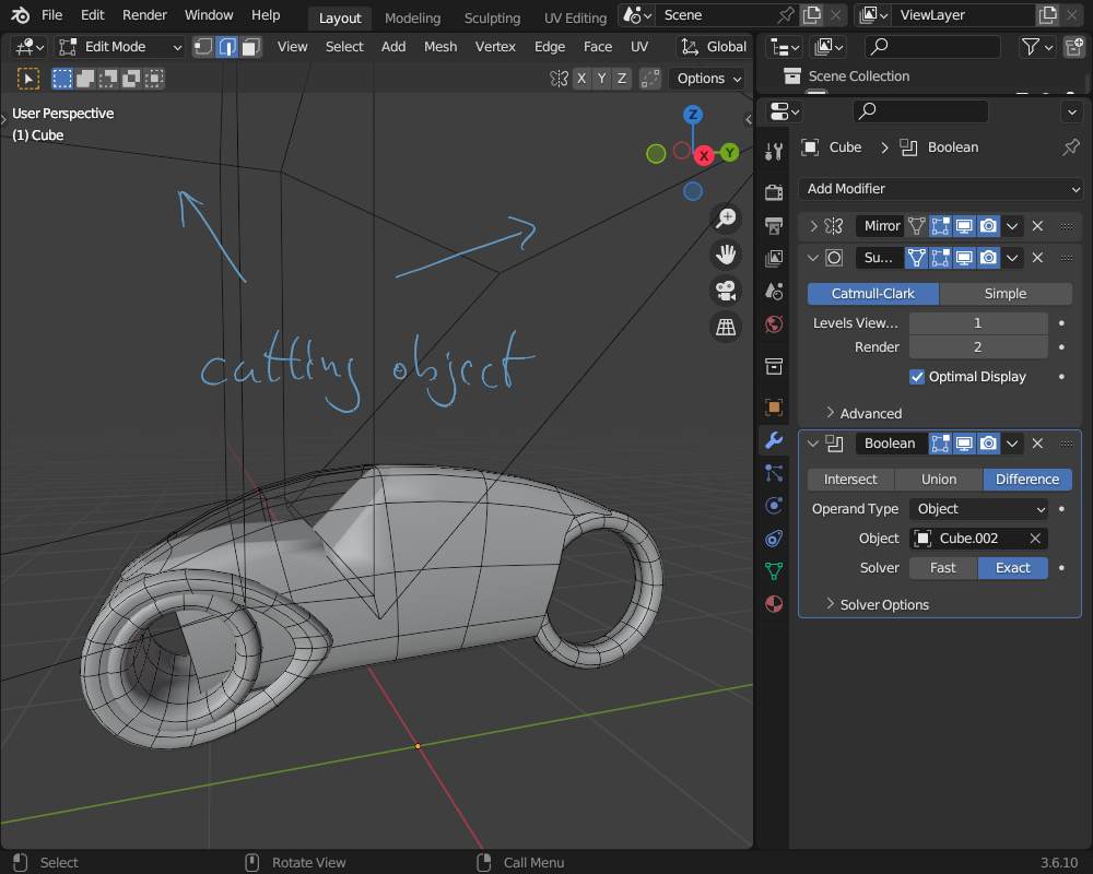
What I want to make is Flynn’s Light Cycle from Tron: Legacy. It’s an updated version of the original Tron Light Cycle design. I’m using the blueprint below as reference. What I’m stumbling with is trying to nail down how to begin modeling the primary shape, starting at the front “wheel”. The shape flows into the body, and it is spherical with what I would determine to be boolean cuts on the sides, another boolean for the wheel-center hole, and then the rest of the details are inset cuts? Also, what is the method for creating panel cuts to make line cuts to make an object appear to be separate pieces?
I’m having trouble figuring out how to make that initial round shape (Can’t say I’m fully confident in knowing the rest either), and then beyond that shape, having it flow into the rest of the body. Could this be a re-mesh thing, something else I don’t really have experience working with? This might be too much of a challenge for me to tackle with my knowledge and skill-set, but I am always eager to learn and better educate myself! Typically I would be able to follow a tutorial to make something complex like this, but surprisingly there aren’t any topics or videos covering this particular model. I’m not even sure how much can really be explained compared to how much I should really have a formal education in this type of thing. Thank you for your continued support and patience.
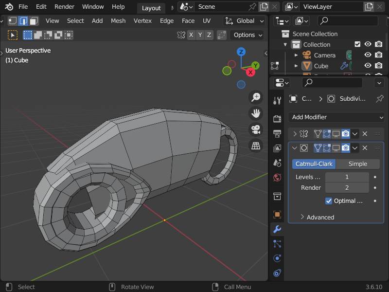
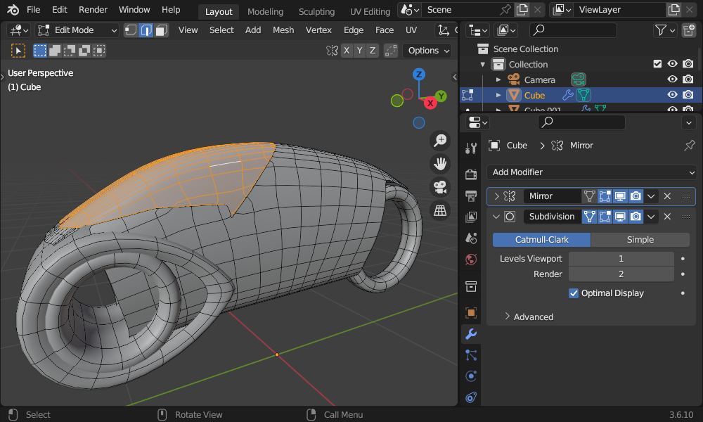
Yes! How did you make the front raindrop shape? I’ve tried a cylinder, a cube with a bevel, and a torus but haven’t found the proper topology to make it work.
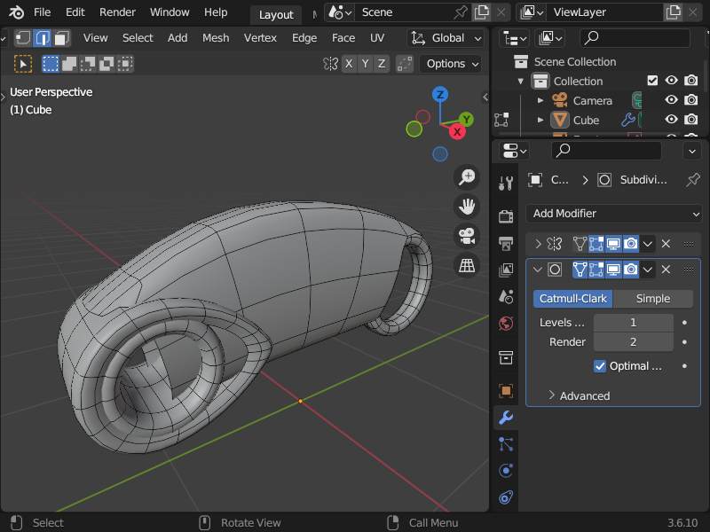
Edit: I believe I made it work! I just needed a starting point, at this point I think it is a matter of understanding correct topology and subdivision.
Moving with proportional editing on one edegloop and seleceting two other edgeloops and scaleing… also addin two edgeloops… so it is "a bit more to the final shape.
To be honest it would be even better to start with a cylinder with less edgeloops.
Also cutting the reference into individual views and also aligning and scaling them can help… especially useng the same quadratic image size… to align them in 3D perfectly (which i didn’t do here because it was only quick example…).
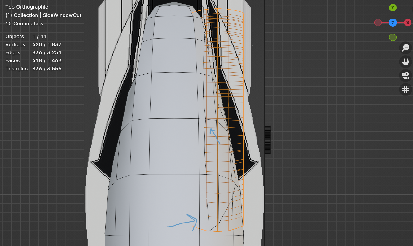
I do indeed have the different views aligned in my viewer. I recreated your shape of the body as well, but now I’m stuck again, how do I cut out the shape of the windows on the mesh and make them retain their shape when subdivided and also avoid tris and n-gons so there aren’t jagged points in my mesh as well?
“Cutting out” from an already establish form is indeed not very easy… one way is to make simple cuts and then realign the surrounding geometry… in belnder there is the posibiltiy to make a copy for “hold the form” and then shrinwrap the cuted piece on it and apply the modifer…
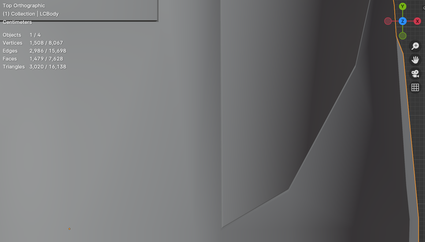
The cut comes out crooked because of the cutter being a extruded flat shape from a curve I made to match the side window. How do I make it follow the curve of the mesh in a straight line?
Edit: So it was mostly about matching up the amount of loops on my cutter to the loops on the mesh and then had to manually line it up a little after. Now I’m trying to incorporate the shapes of the shell.
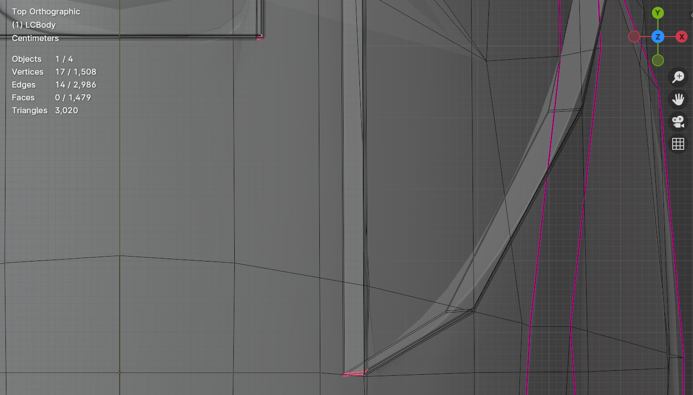
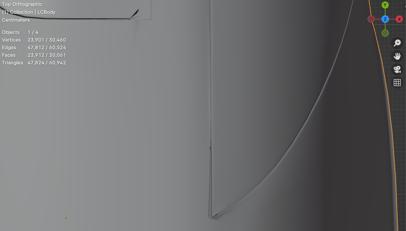
So I just figured out about edge creases, and I’m trying to use them to keep the sharp edges of part of the windshields. However, I’m having issues with faces overlapping each other inside of the slim border around the windshield when subdivided. I’ve tried variations of edge creases, taking away one, adding another, and it all gives a similar result. Is there a secret trick for doing edge creases in this particular circumstance?
Edit: Issue seems to be coming from too many edge loops due to beveling. I gather I need to choose between bevels or edge creases as they do not like to work together.