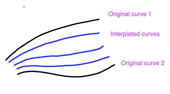
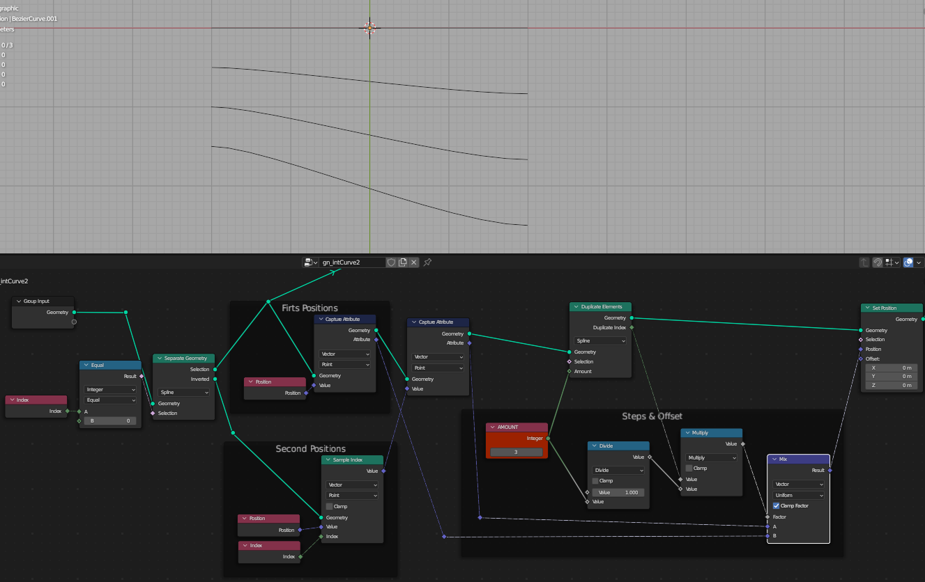
I am trying to interpolate additional curves between two drawn bezier curves. Here is a rough image of what I am trying to do (the black lines represent the original bezier curves, the blue are what I want to create):
I have stored the original indices of each point and correlated them with each spline. So if you look at the spreadsheet, each point has two custom attributes on it that indicate which spline that point belongs to and which index each point has (so they can be correlated with each other).
What I need to do is calculate the distance between corresponding points on the original two curves, and then divide that distance by the number of interpolated splines being added. That will give me a step size.
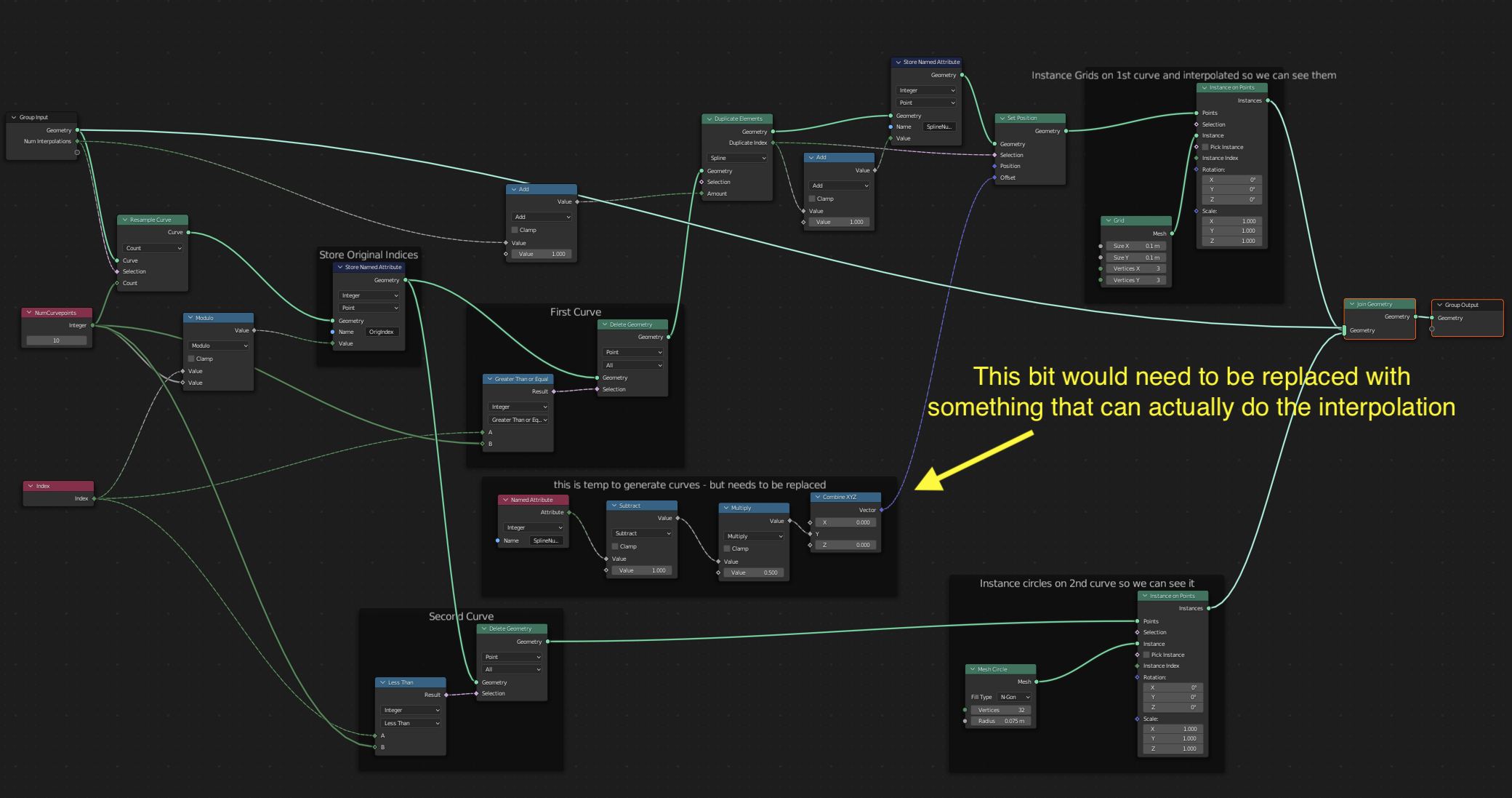
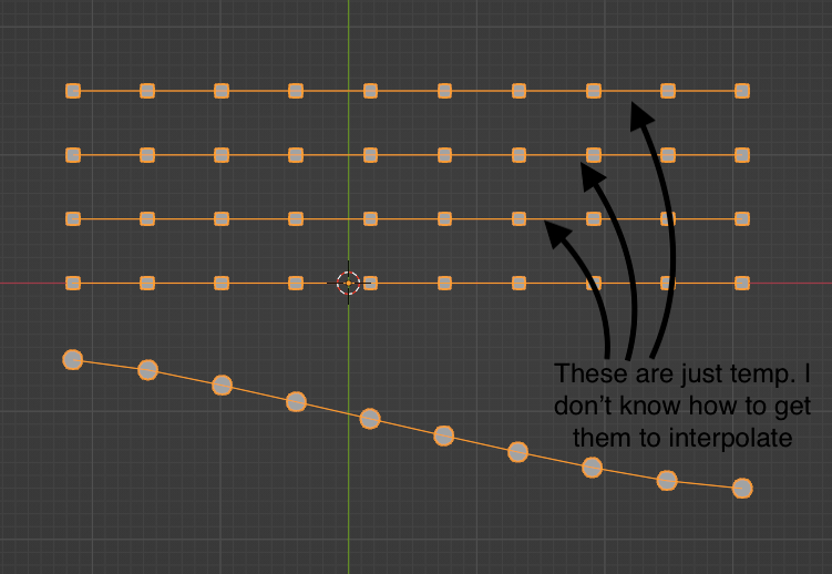
But I don’t know how to go about doing that (both how to specify which points to use to find the distance and which math nodes to use to calculate that distance).
The next tripping point I have is that I don’t know how to set the position of the interpolated points so that they lie on the line that could be drawn from the corresponding points on the original two curves.
Basically I am stuck both procedurally (how to identify points to use to calculate distances) and mathematically (how to transform distances into 3D coordinates).
Any hints (or even links) that might point me in the right direction are greatly appreciated! Even if it is throwing away all of this network in favor of a better one.
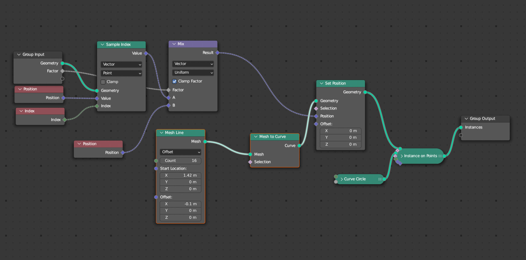
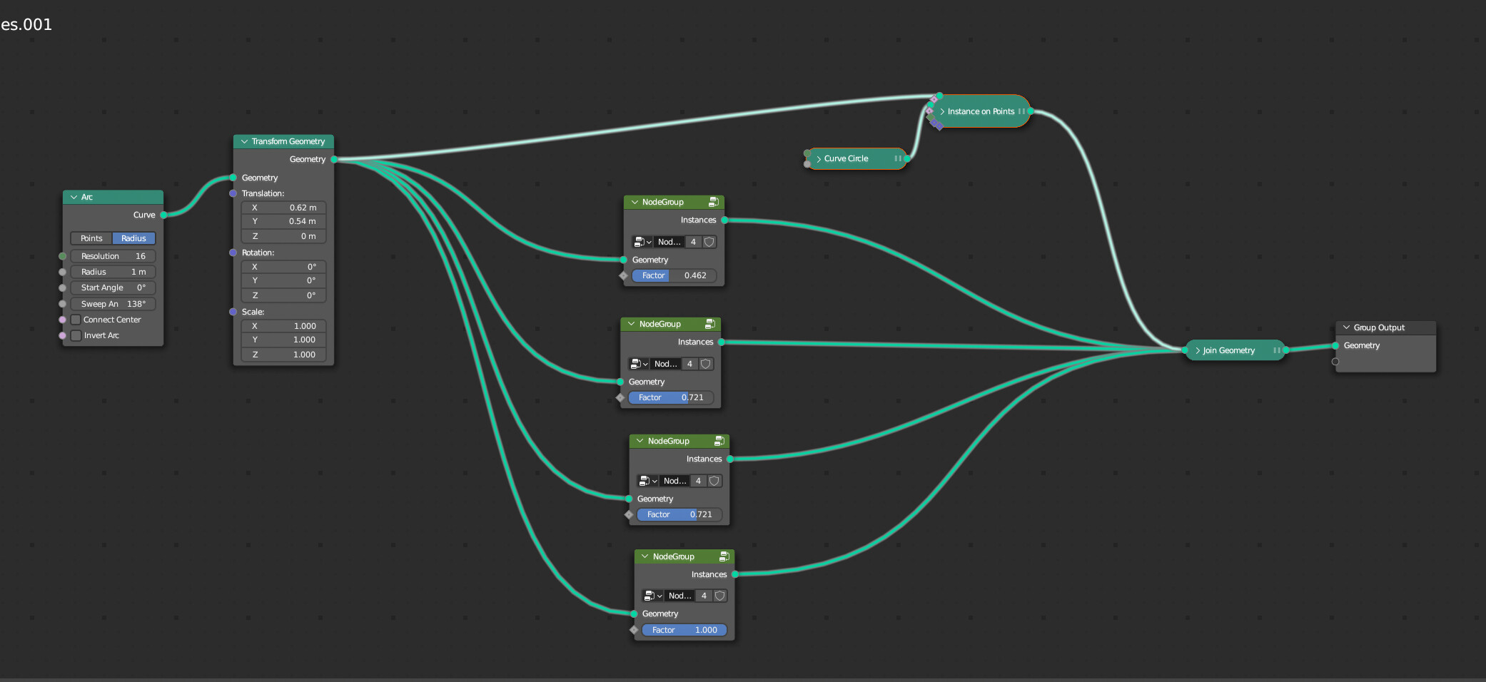
Using the Mix nodes to interpolate between two sets of positions (like in the post above, if I understand correctly). Divide 1 by Amount of curves to get Factor:
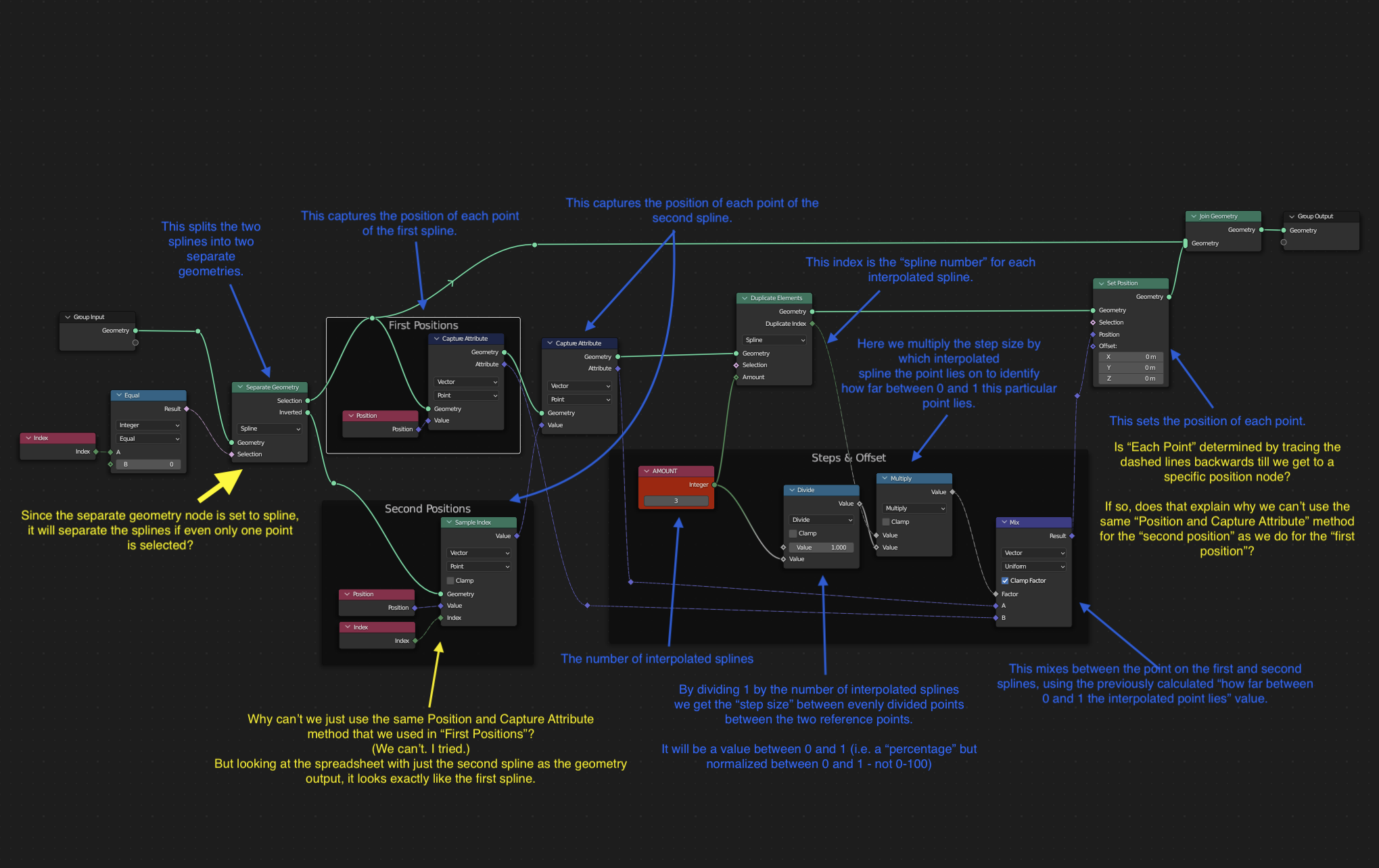
I am trying to understand how it works. I think I mostly understand it, but I do have a few questions if you are willing to answer them. I put the questions into the following image.
Questions are in yellow. Explanations of what each node does is in blue.
Only if you have the time and interest in answering. Thanks!
We have to use “Sample Index” to get the second positions because we capture the attribute of the second spline onto the first one. [It was done with Transfer Attribute node before this update]. As you see, we end up using only the first spline Geometry - the second gets discarded at this point.
It’s like, uh, an array of vector values now recorded on the points of the first spline.
…at least, this is how I understand it.
I’m not sure, I correctly understand the first question though.
We select all the points that correspond to spline index “0” (which have their own indices, much like edges, faces and Mesh Islands).
And yes, it does seem to calculate backwards, until it gets the necessary field. I’m sorry, this is not something I fully understand myself
Hi, I’ve been trying to tackle this problem myself a couple of months ago. There are a couple of new nodes available right now so I would have to revisit my implementation for it to work in the current blender version, but the main struggle then (and IIRC still is) was finding the 3 nearest curves to interpolate from for every curve. I ended up using a pretty obscure setup using a Delaunay triangulation in UV space to find the 3 guides to use for interpolation.
Thanks. Your explanation makes sense. I assumed it was something like that. I can’t say that I fully understand it yet but your description gives me a lot to chew on trying to improve my understanding.
As to the first question, you answered that as well. I assumed the index only referred to points, but it makes sense that splines have their own index as well. Thanks.
That is amazing! I would love to see the network on how that works. I am trying to up my game with regard to geometry nodes and seeing something like that would give me a lot to learn from.
Very impressive! If you ever get around to releasing the scene, please post here (if you remember). That would be cool to play with.