Create 2D CAD drawings with Blender.
This is a small guide to create CAD style 2D technical drawings from 3D models in Blender.

DeskCAD_sample.pdf (348.5 KB)
However, this solution does not replace professional CAD and has some limitations, but it allows you with a little effort to create CAD drawings, and add various elements and do compositing, giving your drawing different styles, which however will not be covered in this guide. in-depth, but you can independently explore various techniques and create your own personal style.
Steps for creating 2D CAD
Organize your 3D project in various collections, and then this will allow you to later use them as instances to insert, in the various 2D layouts that you will create, and to organize the various operations for the realization.
The collections can be nested, in sub-assemblies, this will also allow you to create details, which you can insert into other designs.
Add various scenes to your Blender file, to be used to then insert your various elements that will make up the final 2D drawing…
I personally name the various scenes with a numerical suffix and a description of their content, but you can of course assign names or descriptions that you consider correct, the names I used in the file of this example are those listed below, in this way you can understand quickly where the various elements are, it will be enough that they make sense to you.
- 01.Project
- 02.2D_LA_DWG
- 02.2D_Text&Note
- 03.A3H_template
Description of the contents of the various scenes in the attached example file.
01.Project
This scene contains the source 3D files of the model, which can be modified and updated without having to worry too much about the 2D layout, which will be generated later, because instances of the collections will be used, which will consequently be connected and therefore updated, automatically, if you modify the source collection, in the scenes where the various elements will be inserted, which will be used in the 2D layout for rendering the CAD drawing.
3D model in the scene 01.Project

02.2D_LA_DWG
In this scene, we have inserted an instance of the overall 3D desk model assembly (ASM_Desk) that is in the 01.Project scene.
This scene is organized with collections to avoid confusion with other elements used in the scene such as texts and dimensions, or as for 2D outline elements made with Grease Pencil objects with the Line Art modifier In fact, the collections allow you to activate or deactivate them as needed and to limit certain operations to them.
Below is a list with the descriptions of the collections used in this scene, some collections will be useful for rendering, because here, in this case the surfaces have been filtered in the final rendering, but using the composition of various scenes in the final rendering, the complete final image will be assembled.
- stage - Camera and lights
- Ortho_layout - 4 copies of the desk instance (ASM_Desk) rotated for orthogonal projections
- 2D LineArt Grease Pencil objects with Line Art modifier.
- Dim&Note mesh objects for dimensions and texts and various elements
Note that the orthographic camera of this scene will be used by two camera objects, so I have assigned a name to it, which allows me to easily locate it, as it will be used, even in the scene with the elements that will not be visible here, during the rendering because surfaces in the View Layer tab are filtered.
02.2D_Text&Note
This scene will be the one used to composite those elements that will not be visible in the 02.2D_LA_DWG scene, because as has already been said several times, the surface filter has been set, and therefore they will not be calculated in the final rendering.
In addition to having the same camera as the scene 02.2D_LA_DWG, the camera object with the name Camera_2D_LADWG
03.A3H
This scene contains the A3 template with the various texts inserted in the text-box and an orthographic camera.
The landscape A3 template used and shared in the attached file was created by copying the ISO A3 template of QCAD, and to control the thickness of the mesh wire, few geometry nodes were used which will be given below, because they will also be used with other elements such as dimensions and arrows.
Rendering settings in various scenes
It is preferable to use Eevee as a rendering engine, since there will be no surfaces and this will allow the generation of the various scenes to be composed in the final 2D CAD quickly.
The first scene that must be set for rendering is 02.2D_LA_DWG
02.2d_LA_DWG scene settings

Since the rendering must be within the landscape A3 template, you need to configure the final dimensions of the rendering and the correct scale of the orthogonal camera which we have named Camera_2D_LADWG for convenience.
The camera will obviously be positioned above all the elements we wish to include in the final CAD drawing.
I use standard ISO formats and to set a 300DPI rendering for an landscape A3 (420x297)mm I created some predefined formats in Blender, and I obtained this information from GIMP, which allows you to see the resolution when you create a new image.
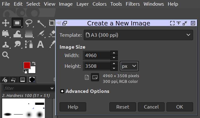
With this trick, you can find the correct resolution for the Rendering output to print with various paper formats.
Standard paper sizes ISO landscape 300ppi in pixels
- A0 14043 x 9933
- A1 9933 x 7016
- A2 7016 x 4960
- A3 4960 x 3508
- A4 3508 x 2480
Landscape ISO paper dimensions in mm
- A0 1188 x 840
- A1 840 x 594
- A2 594 x 420
- A3 420 x 297
- A4 297 x 210
This information is useful because it is used to create predefined squaring templates and set the correct rendering dimensions for the various paper formats.
Furthermore, depending on the standard formats used, it will be very simple to set the scale of the orthographic camera as well.
Scale and paper format management
For example in this case, in the example 3D file, an landscape A3 template is used therefore, the rendering dimensions to have a final image at 300DPI, the resolution must be 4960 x 3508 and the orthographic camera scale is 4.200, which in this case is a 1:10 scale, which allows you to include the entire drawing with the various orthogonal projections.
therefore for an A3 format the reference value 420mm (the horizontal side) therefore it will be sufficient to multiply 0.420x10 and the result is 4,200, since Blender uses metres as the default unit , with this scale value we would have a final rendering with the correct scale on the A3 sheet of 1:10 and it also be used as a reference drawing for production with correct dimensions if it is printed on A3 paper at 300DPI.
The scale may also be the one you deem appropriate for your purposes, but in the 2D CAD technical drawing we try to use standard scales, however nothing prevents you from using other scale values, it will only be enough to multiply the horizontal side of your squaring by what you deem appropriate to use as a scale, and of course you can also use different formats and customized resolutions.
Standard scales for technical drawings
| ANSI (US) | ISO |
|---|---|
| 1:1 | 1:1 |
| 1:2 | 1:2 |
| 1:4 | 1:5 |
| 1:8 | 1:10 |
| 1:10 | 1:20 |
Formats with high resolutions could be problematic with old computers and low performance, so Blender could crash and close unexpectedly. I recommend using A3 or A2 initially, which are also the paper formats that we can print with home printers.
Camera_2D_LADWG Settings
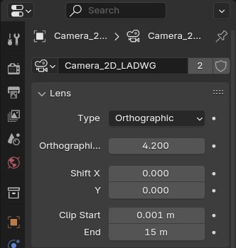
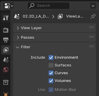
The images above are the settings used in the example file, and as you can see from the second image, the surfaces have been disabled, so they will not be calculated in the rendering process and unfortunately not even in the 3D view, if you use in-view rendering.
Settings 02.2D_Text&Note

This scene will be used to render the mesh elements that are not visible in the previous scene, which are dimensions and other elements that we will add such as texts or arrows, and which are also excluded from the calculation of Grease Pencil’s Line Art modifier.
Instances
Since in the main scene, the scene 02.2d_LA_DWG everything is organized into various collections, to connect elements such as dimensions and texts not visible in the final rendering in this scene, it will be sufficient to add those 2D_Text&Note to this scene missing collections, adding the instances of the collection prepared for this purpose, and which must be visible in the final 2D drawing, in this case it is simple because in the example file everything is in the collection Text¬e
To add the instances from the Add menu and select “Collection Instance…” in this way an instance will be added which will be positioned with the same coordinates.
Camera
We add a camera by positioning it above the elements, and from the Data panel of the camera ![]() , we connect this camera to that of the scene 02.2d_LA_DWG by selecting from the menu the
, we connect this camera to that of the scene 02.2d_LA_DWG by selecting from the menu the ![]() in this way it will have the same scale as the drawing, without changing settings
in this way it will have the same scale as the drawing, without changing settings
Another thing to do is the resolution settings, which obviously will have to be the same in all scenes so in this case where a landscape A3 at 300DPI is used it will be the same 4960 x 3508
In the rendering properties panel, on the Film tab, activate the Transparent option, this option must be activated in all three scenes to easily allow you to composite the various scenes into final image.
Settings 03.A3H_template

In this scene a template of an A3 landscape, is inserted in millimeters, so an object has been created only with the mesh wires, various boxes connected and with a modifier to add thicknesses to the lines, the geometric node used will be shown later.
This template box, contains the texts and information of the drawing, which can be modified and customized according to needs, it will also be possible to make multiple templates that can be used for different elements.
Camera
The camera used has a scale equal to the horizontal side, so it will be sufficient to set the value 0.420 (A3 side), while the rendering resolution must be the usual one of 4960 x 3508 and activate the Transparent option as already done for the other scenes.
Using dimensions.
Dimensions are the most tedious part of generating technical drawings with Blender, but with a few small tricks you can get around the difficulties.
- You can create your own geometries
- or use additional components
- or use what I prepared
Create geometry for dimensions
The objects for dimensions are very simple and can be created simply with mesh wires, as for the A3 template, and using the geometric nodes it will be possible to give a thickness and this will make them visible in the rendering by modulating the value to make the meshes visible .
These lines and arrows must have dimensions that can be visible in the final image, and various strategies can be used to ensure that the final scale is correct, for example if the dimensions must be as in this case on an A3 sheet with a scale of 1:10, you can create the geometric elements in mm and then scale by x10, but with a little experience you will understand how to do it easily.
Each mesh object has its own local coordinates and with the use of the snap on the vertices this allows you to measure the various elements and you can constrain the movements with the local axes, while for the text simple text objects are used which are modified manually, but there are some added components that automate and are simple to use, some paid and others free like this MeasureIt_ARCH which has complete documentation that can be consulted here in this link MeasureIt_ARCH Docs
While a paid one is this one Geometry Nodes Dimensions System
But there are others and you can create your own.
This GIF image shows how a manually created object can be used for various sizes, it is a tedious job but if you think that once upon a time the technicians did all this manually, writing everything on paper, then you will understand that it is not that tiring.
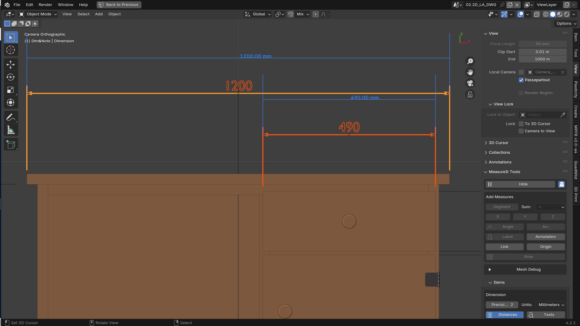
How to use dimensions in the file
This Dimension object for measuring was created with geometry nodes to facilitate users for this purpose in Blender and was created while writing this guide, I’m not good with geometry nodes, but I hope others can expand on this tool and make it available to everyone in the future.
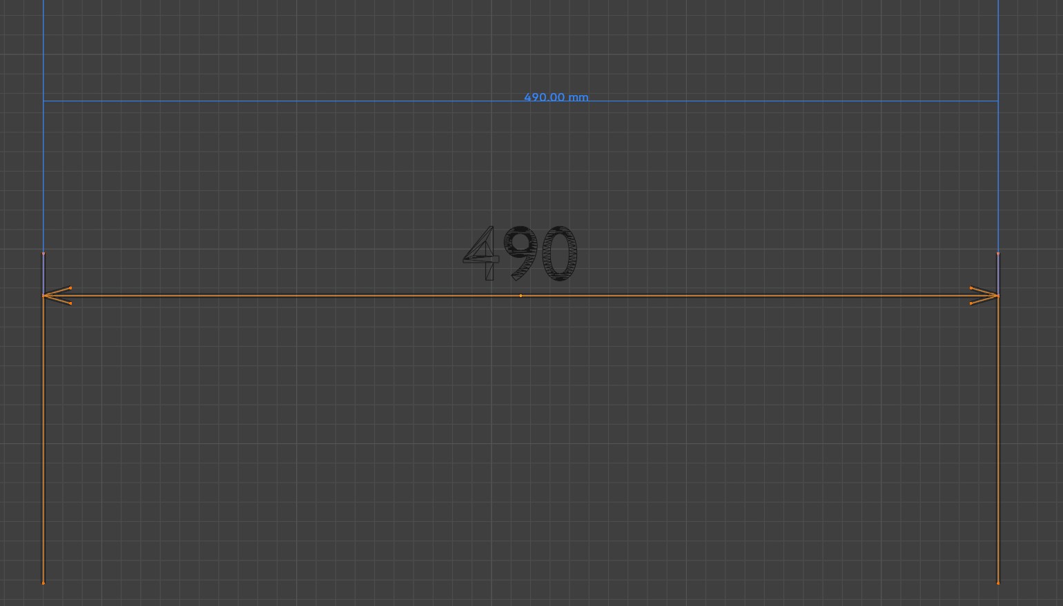
This Dimension object made with geometry nodes is composed of a line that is processed to generate only linear dimensions, for angles and other types of dimensions, you will have to find alternative solutions, but this can be adapted to many cases.
The line must be used in edit mode and move the vertices relative to the local coordinates, on the X axis of the Dimension object and use the snaps on the meshes to hook the vertices to the 3D geometries.
This type of dimension is specifically made to be used only for 2D CAD drawings in Blender, not for 3D views, but you can adapt and modify the geometry node if necessary.
The video below briefly illustrates its use
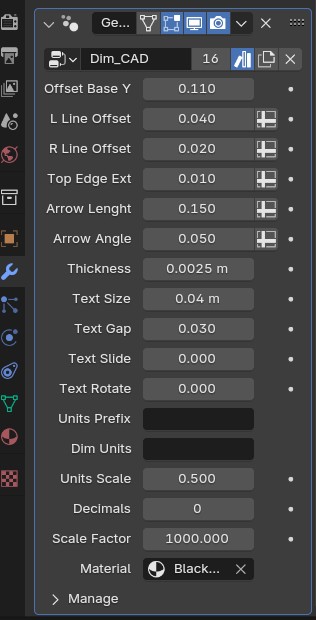
The Scale Factor field can also be used to convert to other units of measurement such as imperial, using the correct value as in the example video above, 1 meter = 3.28084 Feet, but also to use the millimeters instead of meters, in this case 1000 was entered, i.e. 1 meter = 1000 mm, while Units scale is a value for different scales of objects in the drawing as details, such as *2:1 * entering a value of 0.5 or 1:10 entering 10.0 or 1:5 entering the value 5.0 is very simple once you understand the functioning of the scales in the drawings.
You can customize various elements of the dimensions uniquely.
with a little practice it will be easy to use this Dimension object in your drawings in Blender.
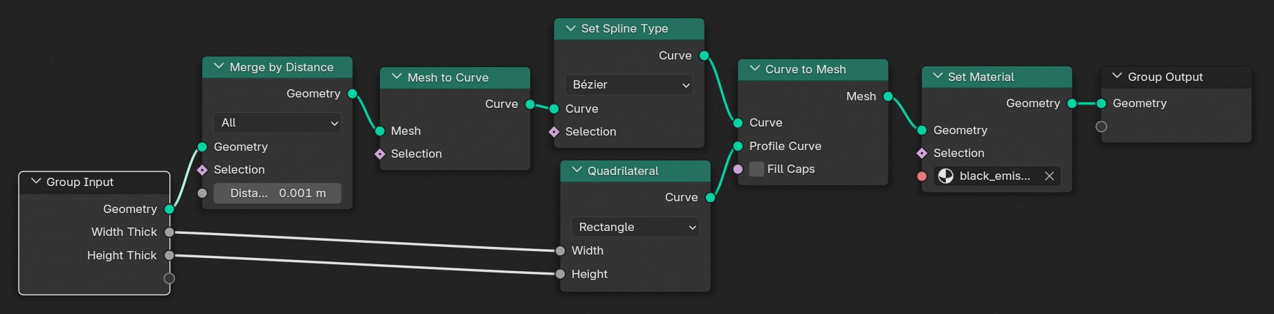
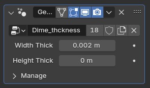
Thickness of lines with Geometry Nodes
This is the Geometry Node that can be used to give thickness to the mesh lines, with a black emissive material (black_emission) with an intensity of 1.
In the example file this node was used with different values for the A3 squaring and for other indications, in this way you can work only with the mesh threads and set the thicknesses depending on the scale.
Basic use of Grease Pencil Line Art
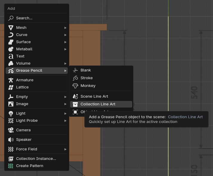
To generate the technical drawing of the 3D objects that have been placed in the view a Grease Pencil object must be added with the Line Art modifier, there is a default command in the add menu.
For convenience I select the instances to move the cursor to the center of the selection, in this way the center of the Grease Pencil object will coincide with that of the cursor, it will be at the center of the objects, but it can also be in other areas, this action is not binding.
For the detailed use of Grease Pencil it is recommended to consult the Blender documentation

And add a Grease Pencil object for a collection, and in the modifiers panel assign the correct collection, which in this case is Ortho_layout this will limit the generation only on the selected collection, and will exclude other objects from the calculation and generation of the contours.

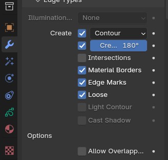
Line Art modifier panel where you set the values.

Below are the various sub-tabs of the Line Art modifier to configure the Grease Pencil object that we have inserted and have a generation of the outlines.
Line Art Modifier
Geometry Processing

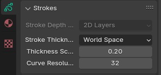
Stroke Thickness
To generate the hidden lines we can either insert another Grease Pencil object or simply duplicate the one we have already inserted and change the occlusion levels by changing the range from 1 to 15, this value is not fixed, a higher value may be necessary or lower depending on the complexity of the scene.
Occlusion range

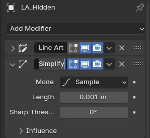
To create dashed lines you need to use two other modifiers and they are Simplify and Dot Dash.
Also in this case you will have to do some tests to find the correct values, the ones I used are those displayed in the images below
Simplify
Dot Dash

With Grease Pencil you can decide what the correct value is in relation to the size of your objects.
For further information on the use of Line Art and Greese Pencil you can consult the Blender manual
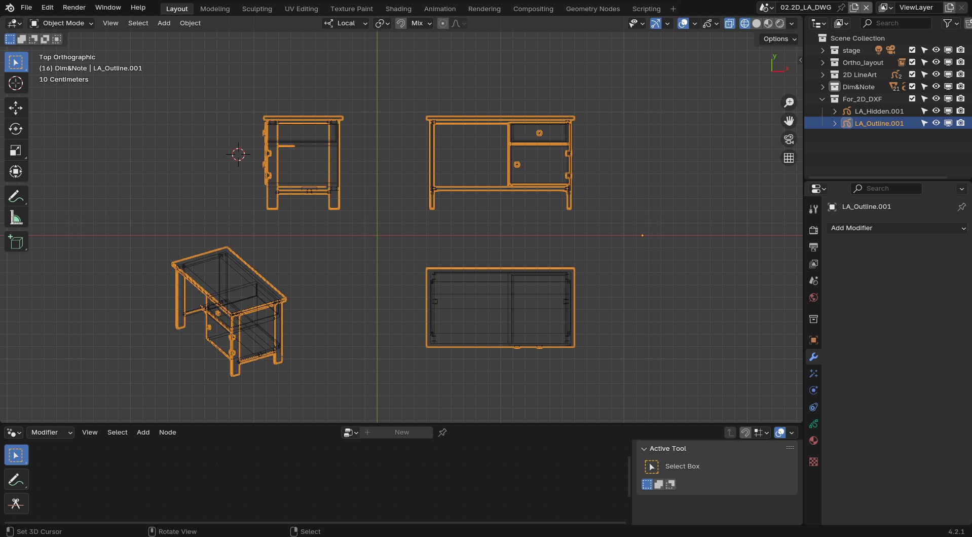
As with the other elements of the scenes, it is also a good idea to organize the Grease Pencil objects into a collection, this allows you to later disable the real-time calculation, in the 3D view because it will make it slow to use the dimension and add other things for rendering the final technical drawing and generally the drawing editing.
Otherwise, with the continuous real-time calculation of LineArt contours, the computer will be slow even if you have an excellent PC.
In this image below, you can see that I have disabled the objects in the 2D LineArt collection containing the two Grease Pencil objects from the 3D view, however this does not prevent them from being generated in the rendered image.

Set the final rendering compositing.
Once we have created all the scenes and set up the rendering in all the scenes we need to use composting to assemble everything, and this will be done in the 02.2d_LA_DWG scene with simple nodes
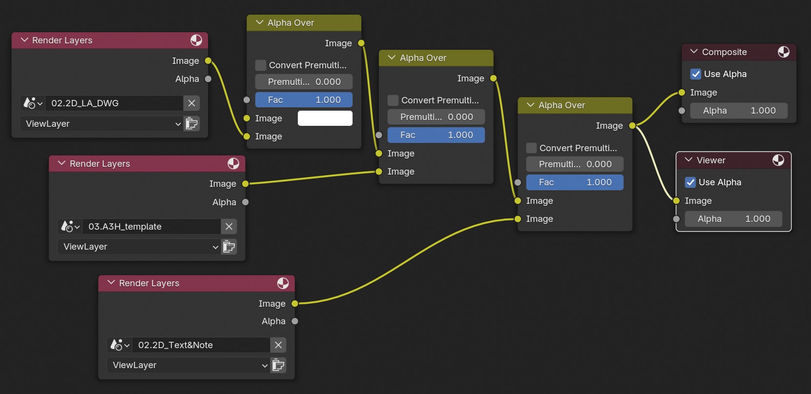
As you can see from the nodes it’s all very simple, the various scenes created are superimposed and using the Transparent option for all.
where the scene with Grease Pencil outlines is mixed with a white color.
So in this simple way we mix the 02.2D_LA_DWG scenes with the pure white, then the squaring in the 03.A3H_template scene and finally the various texts present in the 02.2D_Text&Note scene, and we will quickly have a drawing made up of everything.
It may seem complicated but with this method, you can compose even more complex drawings and rich, with details and other things, in a single final scene, Blender’s compositing is very flexible.
To have a pure white color without grays, you need to change the color management to Standard, and the white will be pure, and will not be taken into consideration in the printing phase.
Using Inkscape
During my tests I discovered that the lines of the drawing are barely visible when printed, and I found a simple solution and that is to use Inkscape to trace the image.
Furthermore, the use of Inkscape also allows you to save PDF documents with the correct paper format and also have very small files.
From this link you can download Inkscape if it is not already present in your operating system.
Trace rendering
Open your rendering with Inkscape and set the size of the document, which in this case is an A3 sheet, then scale the image using the edges of the document as a reference.
Then go to the menu Path and select Trace Bitmap.
Since the image is black and white, if you set a high threshold value of 0.900 you will have good outline tracing, and even the smallest details will be visible.
Once the rendering has been traced, you can delete the drawing and then export the document as a PDF.
The short video below shows the steps for this drawing conversion with Inkscape.
Export to DXF
This is a DXF printed in PDF from Blender Grease Pencil with QCAD

Desk_2D_CAD.pdf (203.2 KB)
This image below shows that a new collection has been created and the copies of the two Grease Pencil objects have been moved, where the Line Art modifier has been applied, for the hidden lines the others used must not be applied, otherwise they will compromise the DXF file, the dashed lines will need to be set later in 2D CAD applications
It is also possible to save the drawing in DXF by saving the Grease Pencil objects by applying the Line Art modifier and projecting the Grease pencil strokes of the contours onto a plane and making some steps to clean and reduce the vertices.
Then convert the Grease Pencil object into poly curves and then into mesh and do further cleaning, eliminating double vertices, and finally export to DXF with the Blender add-on.
Option to export to DXF with the add-on
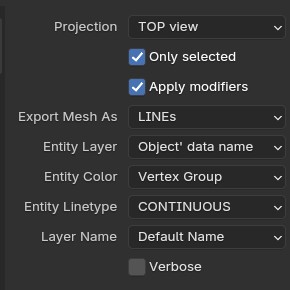
Remember that Blender uses meters as the default unit, so to have a DXF file in mm you will have to scale x1000 before exporting or you will have to do it later in the CAD program
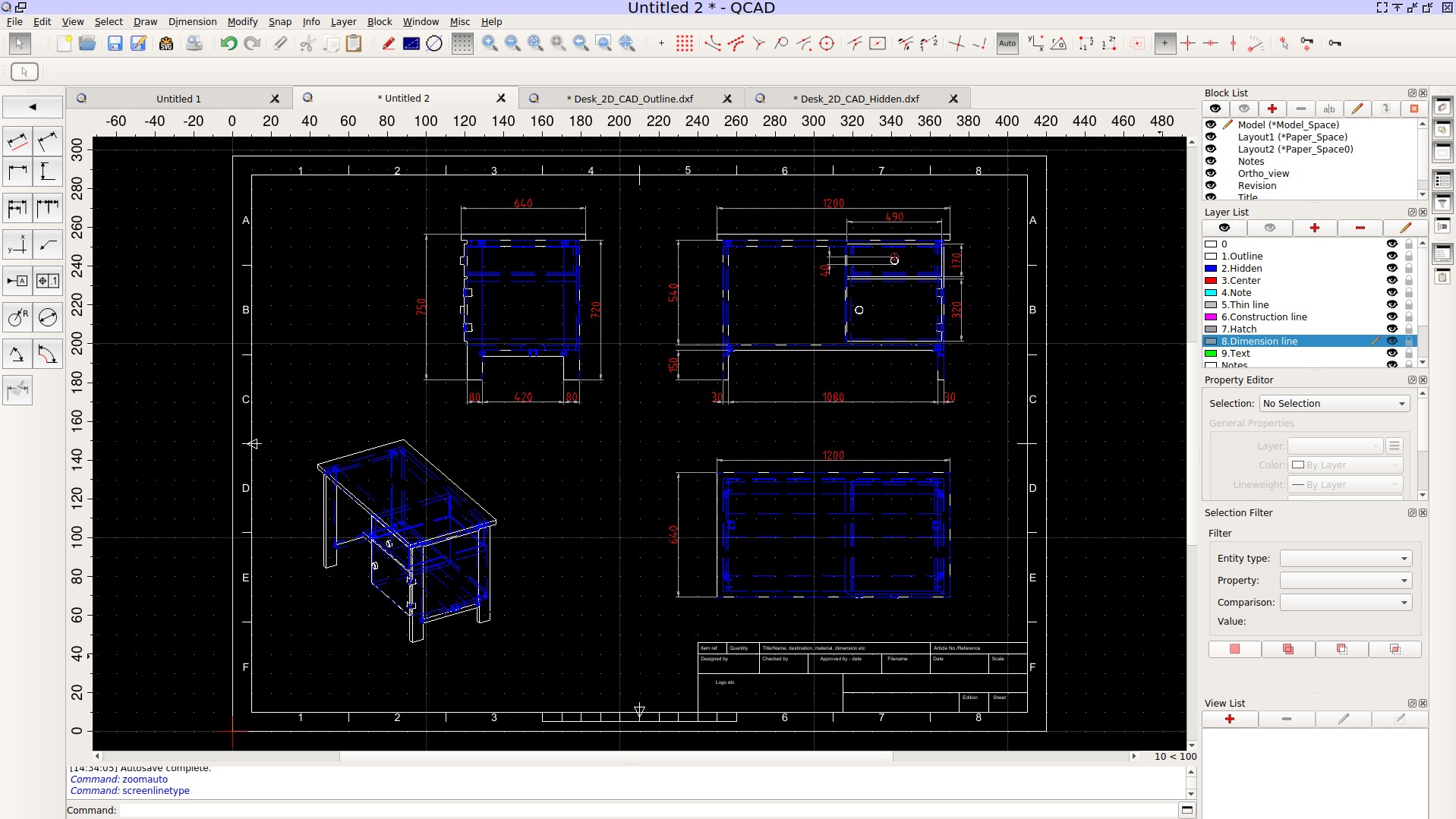
This is the composition of the visible and hidden lines with QCAD, and inserted an A3 as a CAD block with a scale of 1:10 as for what we did with Blender.
However, this final part is not in-depth, but I believe that this initial input may be sufficient, with some testing you can do it yourself.
If it is not necessary to have a DXF file I do not recommend doing this step because with complex models the exported files are large and the Greese Pencil lines are a bit messy and are not as perfect as those you could do with 2D CAD manually, and you will have to do some correction.
Unfortunately Grease Pencil has some defects and it may happen that some lines are not completely visible and other errors, these problems could be solved in the future.
The file also has settings for FreeStyle that you can activate but this part is not in depth, FreeStyle creates very good designs, however it has terrible performance, and with complex designs the computer may freeze for a long time.
In the Zip File attached below you will find both the Blender source 3D file with the geometry nodes for the thickness and the one for the dimensions.
The Geometry nodes for the measurements, was update and now are more flexible and simple than the one explained here in the tutorial.
Desk_2D_CAD.zip (1.6 MB)
In the next days I will share some video on how use the measurements nodes.


