I’m enjoying watching this come together. Good job so far.
2 Likes
how did you do the hull shape ?
Nurbs curves ?
it looks very smooth
problem using image maps
is that they are only good at certain angles of camera
and you have to guess at what angle the images were taken
and when you have spec bump map again if you change camera angle it might not render being realist
so it is an approximation in any case
you could find some procedural wood texture to get better render at any angle but with limited wood patterns!
thanks
happy bl
Thanks for the words, Mark.
Ricky, i modeled the hull by hand.(maybe thats why I lost an entire day in that) I created those U shaped edges and then joined the faces on the verticles and then refitted them few times to better fit the actual reference I’ve used for it.
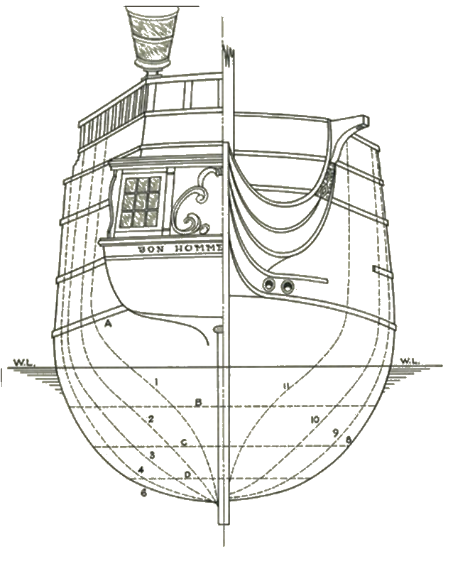
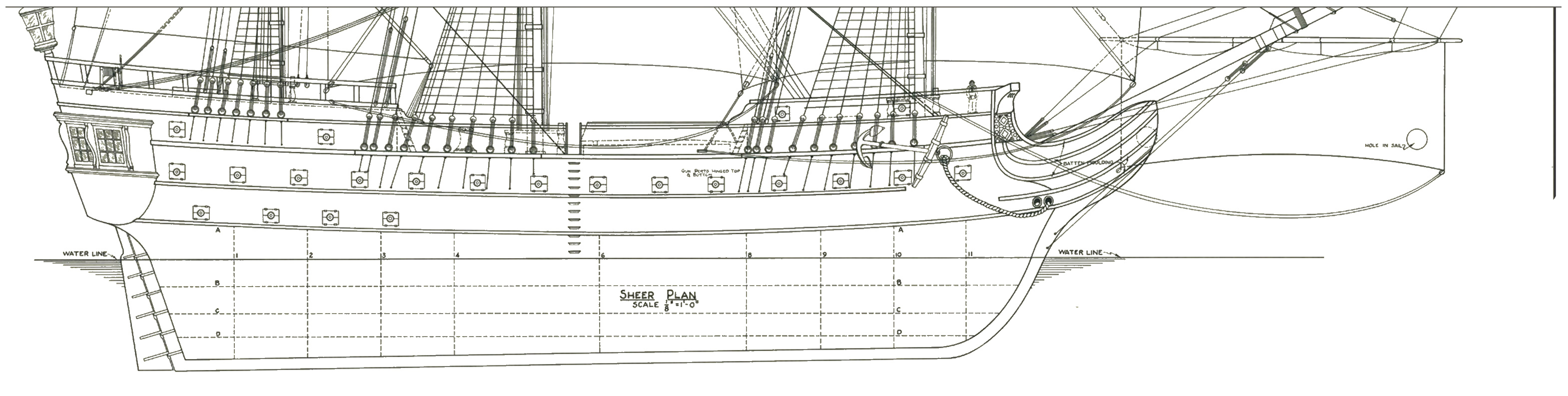
bear in mind, that this is not a historically accurate blueprint. More detailed one is this one, but that one is missing those U lines, along which I could model. But I use it for dimensions and will try to update the ship as much as possible to that shape.

1 Like
most difficult part is the front and back
i’m still looking for some nice tut on that for Spanish galleons!
and what is call planks on the side are not really 1" planks these are
like beam size 6" or 8" thick so not what we today call a plank!
keep up the good work
happy bl
How many texture layers did you use on the wood for the anchor? One for wood and one for grunge?
I see a problem with the helm. The metal texture along the sides isn’t rounded and shows the flat edges of the mesh (no subdivision surface modifier).
You need to make a specular map and plug it into the specular node of the Principled BSDF.
You can use Krita or GIMP to do this,or you can generate one with Substance Painter.
Specular map? Maybe I oughta give it some look into it. I am using diffuse, roughness and metallic maps (if necessary) and normal maps. Today I was modelling and didn’t touch any materials at all ![]()
What do you mean by that “the metal texture is not rounded”? Yes I’ve not used subdivision surface, Iam trying not to use it at all on this project. It’s modeled by hand and somewhere I put more detail, somewhere I didn’t.
I’m using overlapping textures on the anchor. Two materials and one UV map. I’ll have to redo it when I will be finishing that. I was studying UV mapping lil bit after those objects were done, I was real lazy mostly when it comes to that. I enjoy building mostly ![]()
4 Likes
Nice progress.
Your channels and wales seem (to my eye) to be off-scale (channels too thick, wales too thin)
I know the Bonomme Ricard isn’t a well documented ship, but if you look at contemporaries like the Victory and Constitution, it may help with scaling.
1 Like
Interesting model you’re developing! I do have some feedback for you though.
I can see why you’re reluctant to use the subsurf modifier, but I do think you need it - especially on the keel. There’s a few minor adjustments you need to make though.
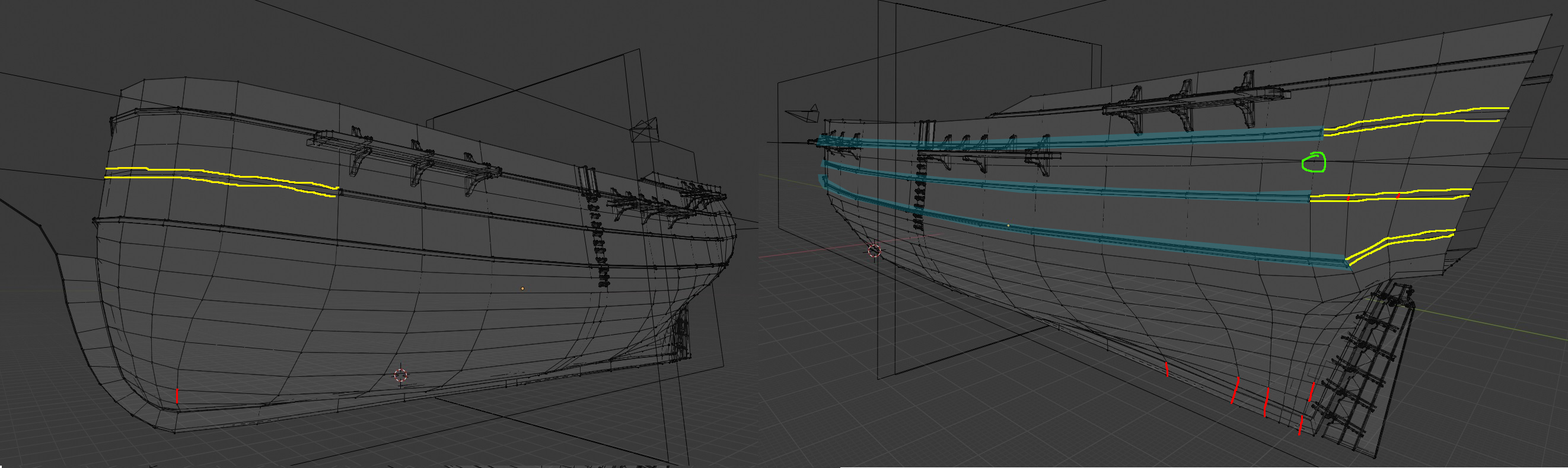
I’ve color-coded some lines for you. I don’t have a tablet though (not posh enough for that haha!) so relying on mousework.
Red lines: nGons - remove these from your mesh. It’s difficult to see if you actually have nGons cos it looks like your image has been compressed and some of the lines have been taken out. Looking at your render though, I’m fairly certain that the keel at the very bottom is definitely an nGon and should be ironed out. The red lines should be edges in this case.
Yellow lines: These will cause pinching if you use a subsurf cos they’re close together. I don’t think you’ll want this. What I would recommend you do to minimise this is to separate the blue (highlighted) vertices into a new object then merge the gap and the yellow vertices together.
Green: Not sure why you saw it necessary to merge here(?) Consider spacing them back out again.
Thanks for responding on my ship and I hope this feedback helps you with yours!
Hi and thank you all for your advices. ![]()
Iam little bit confused, what do you mean by “channels and wales”? You meant like horizontal and vertical edges of mesh? Like that some parts are too close to each other and some have a big distance? Could not even google it up by 3D channels, 3D wales, …
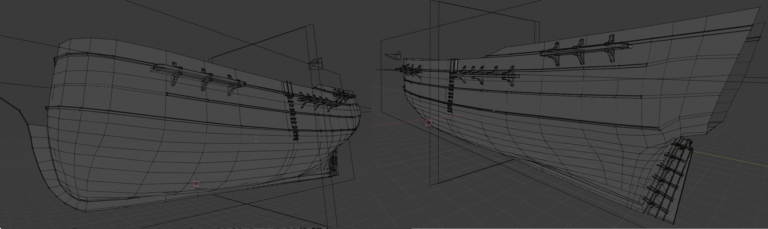
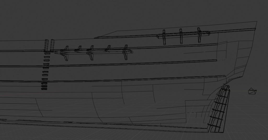
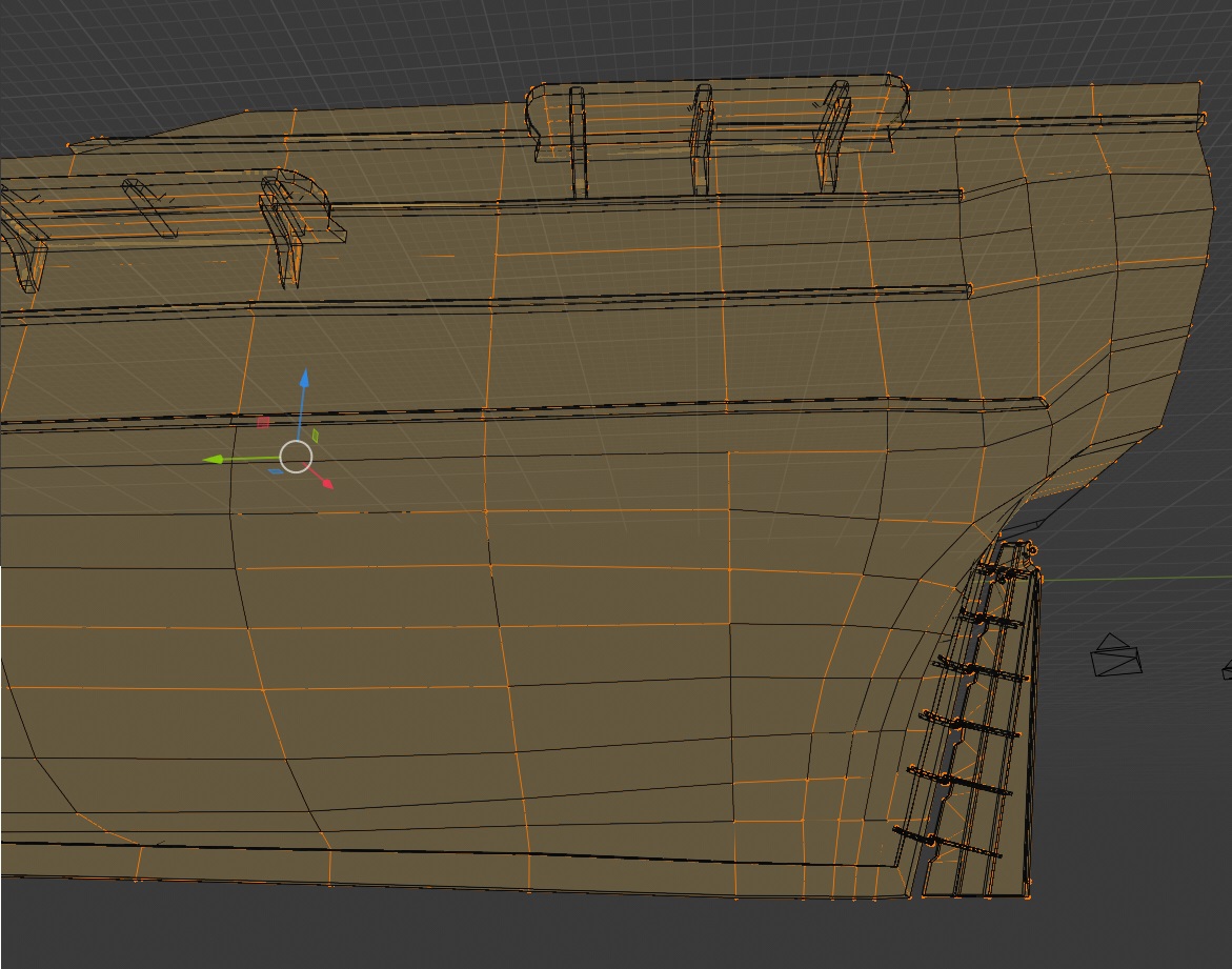
About those red lines Ngons. They are not there in real life. I did not have this problem in 2.49b, 2.5-2.79b but here 2.8 (and now 2.82a) I always get these edges to not show up in object wireframe model, but they are there.
Here is an example. (no double verticles are there, Ive tried even deleting, recalculating normals, …)
About those yellow lines you are very right. Great advice, I just wanted to help myself to build those like they copy the shape of the ship, but they do add unnecessary verticles to another parts of the ship now. After I will finish the shape of the ship I will indeed make them separate.
That green join is an illusion. I left there the object with reference picture from top. ![]()
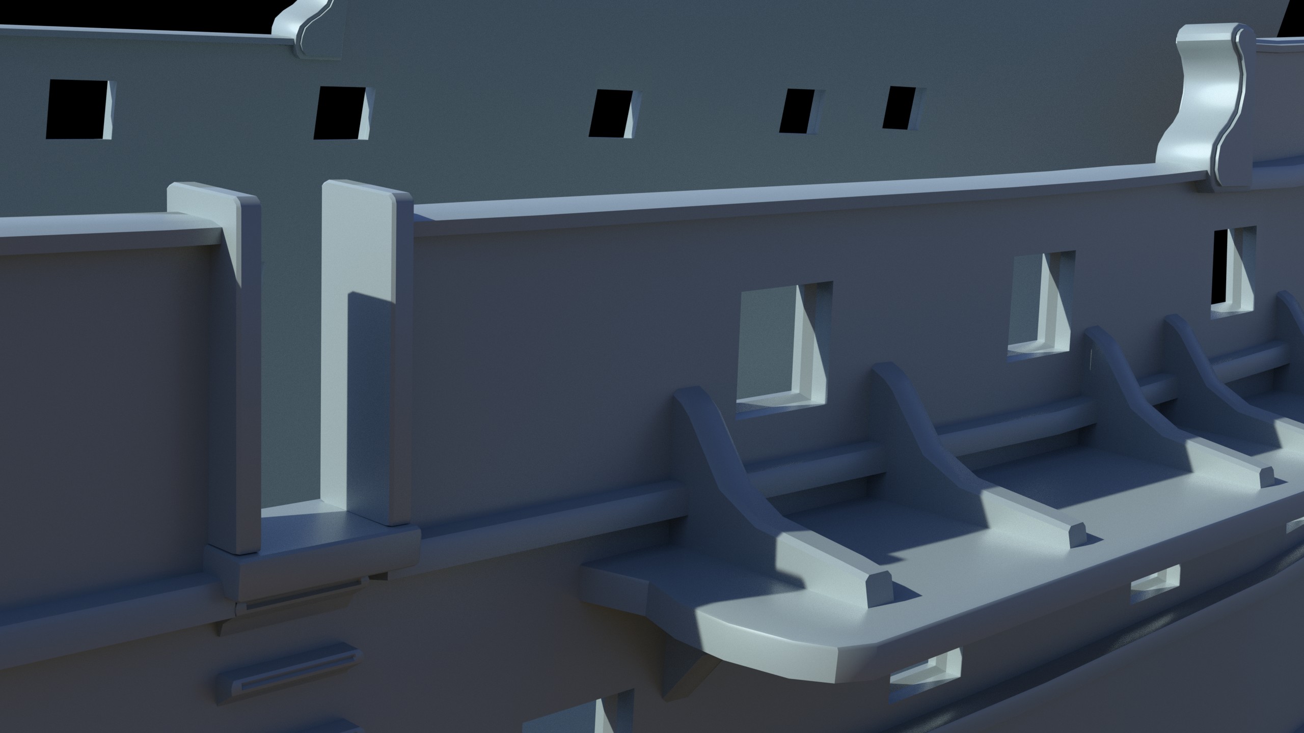
Here are some pictures to document how it looks like.

1 Like
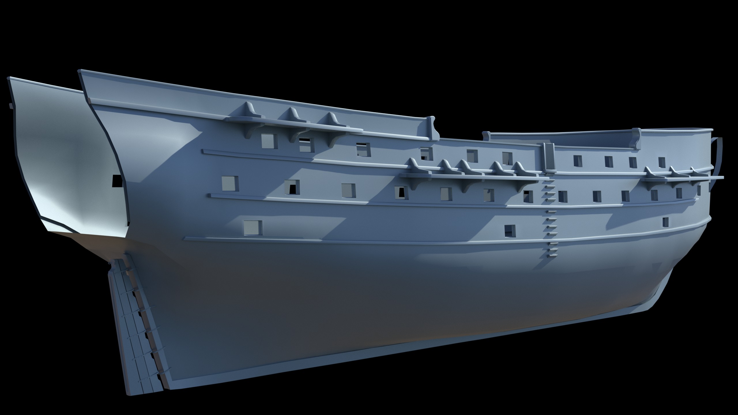


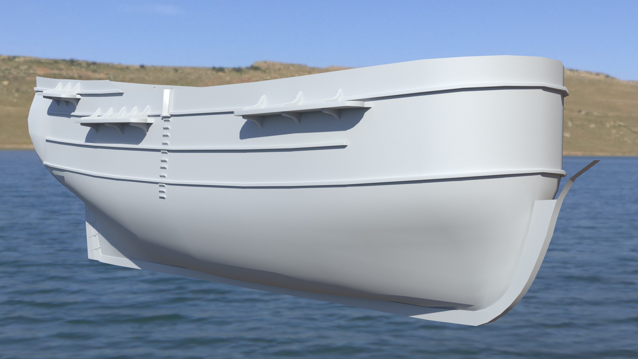
That front image is looking really nice! Perhaps it;s just the camera angle but it feels big. And the detail is very well done.
1 Like
I was working with 2 blueprints and even set up dimensions. I tried to make it shorter and more thin. But then i ve seen the dimensions 11m tall and 11 meters wide doesnt fit. 5 meters is under water thats another dimensions and i ended up with almost what i had before. 
Sorry I wasn’t criticizing, I was complimenting when I said it looked big. I mean it has a sense of being an actual-sized ship. Proportions are all perfect.
1 Like
No, dont be sorry , Iam not taking it as bad critizm. I welcome criticism in my hearth with open arms. Its just that I also felt that it is somehow too big. and still seems. But when calculating according to numbers its ok. weird…
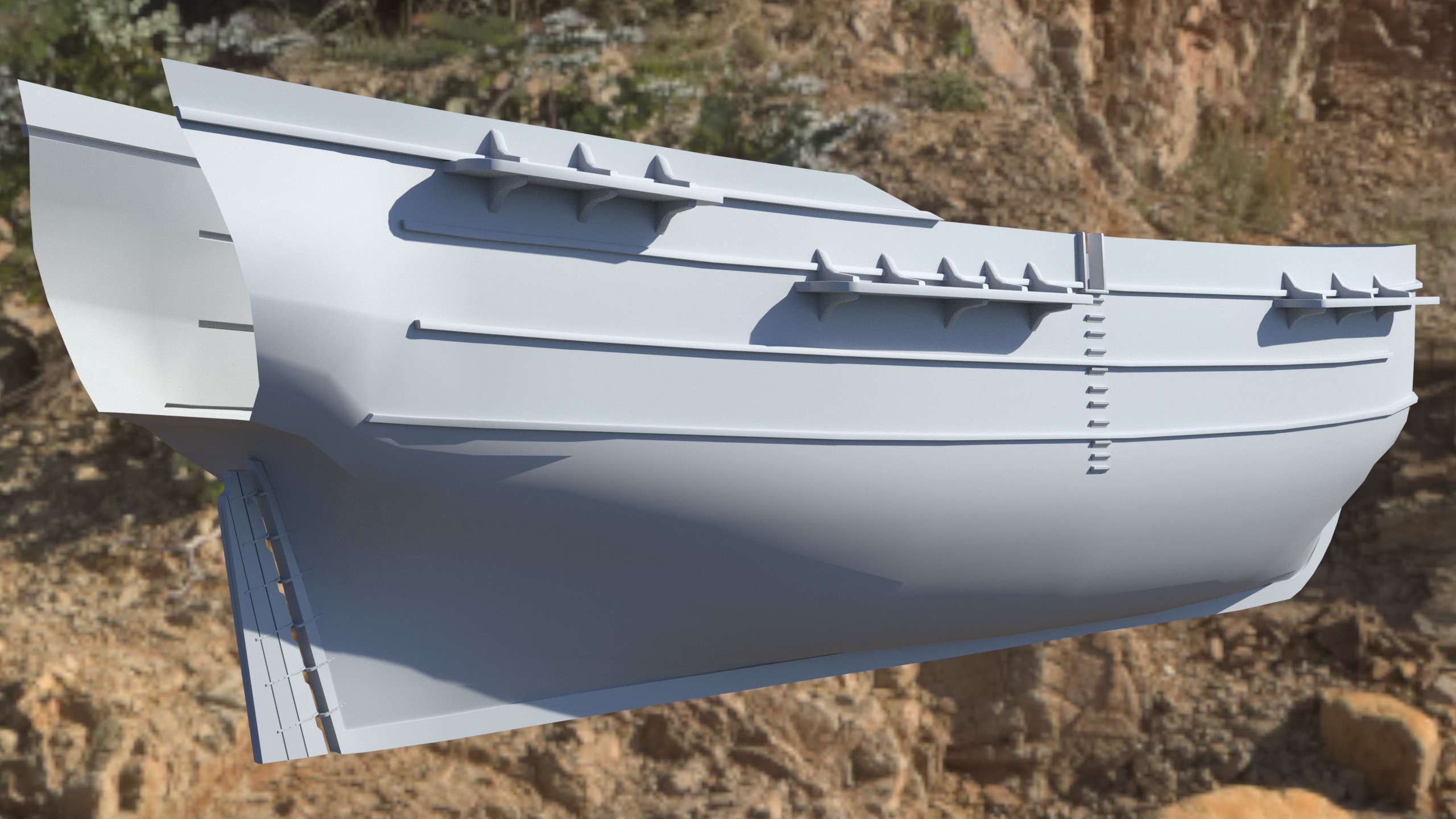
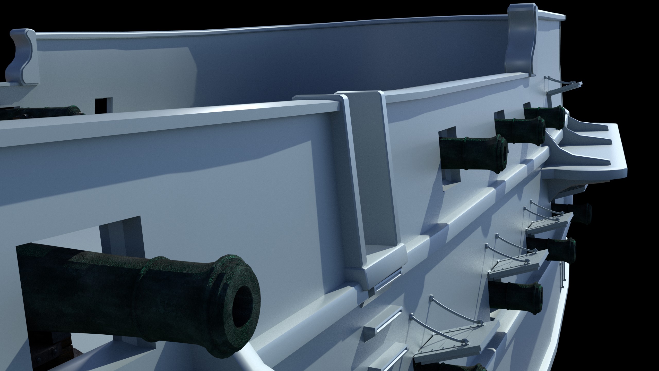
So, finally I got some time to add something to it. Today the work was aimed at gun ports and making a lowpoly cannons that wont be visible from the outside.
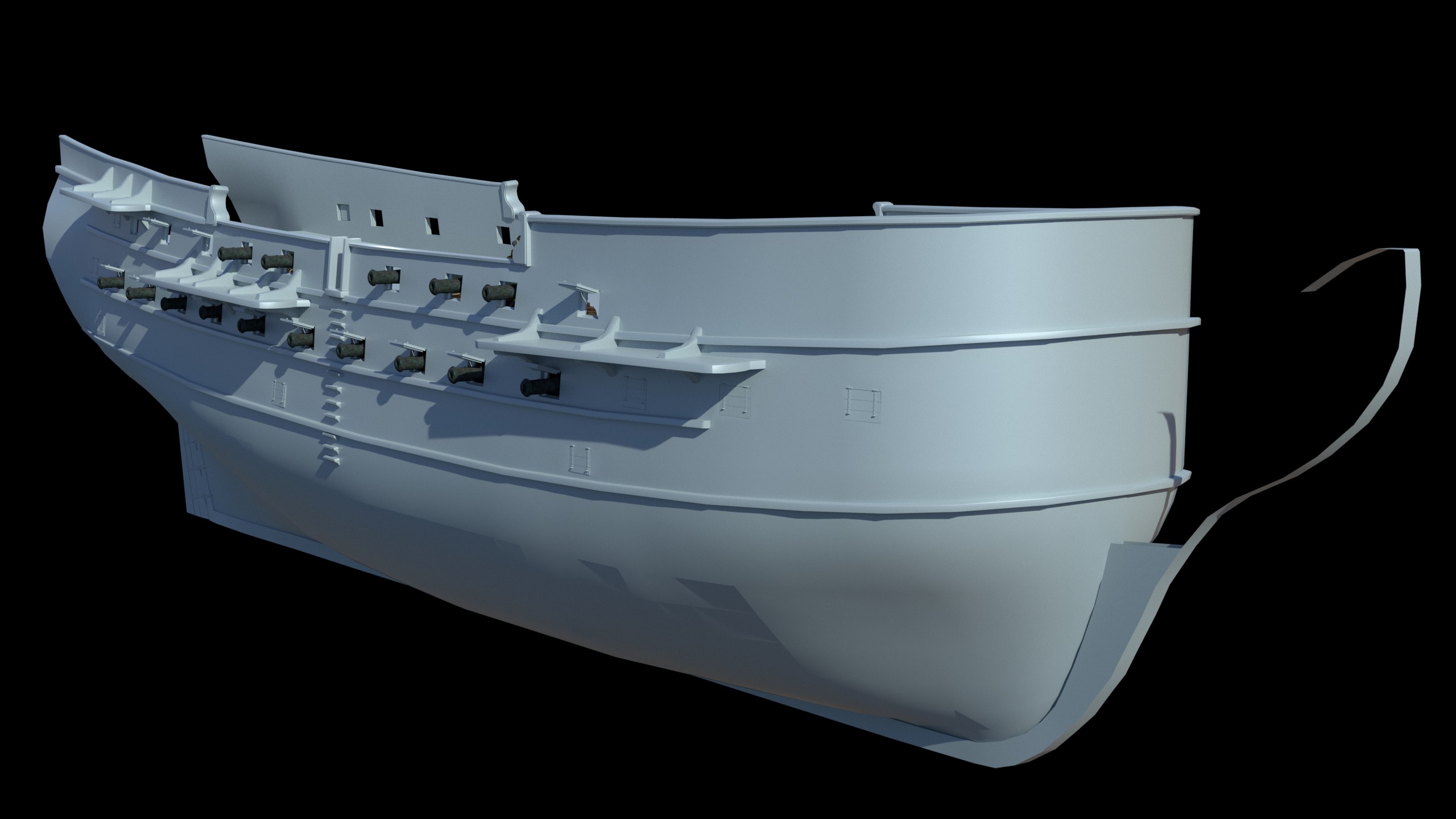

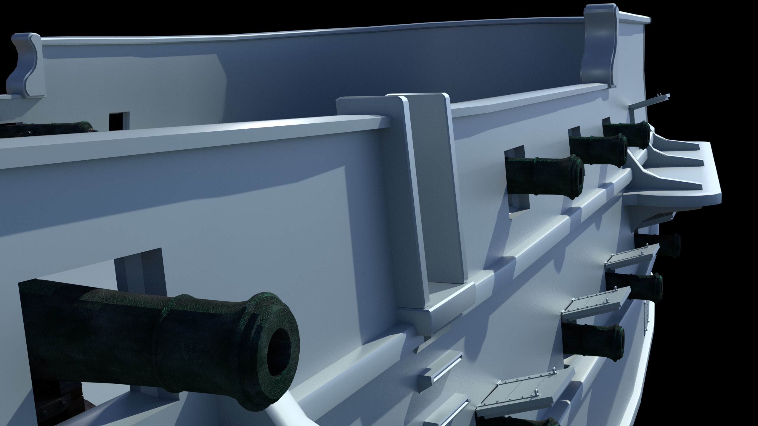
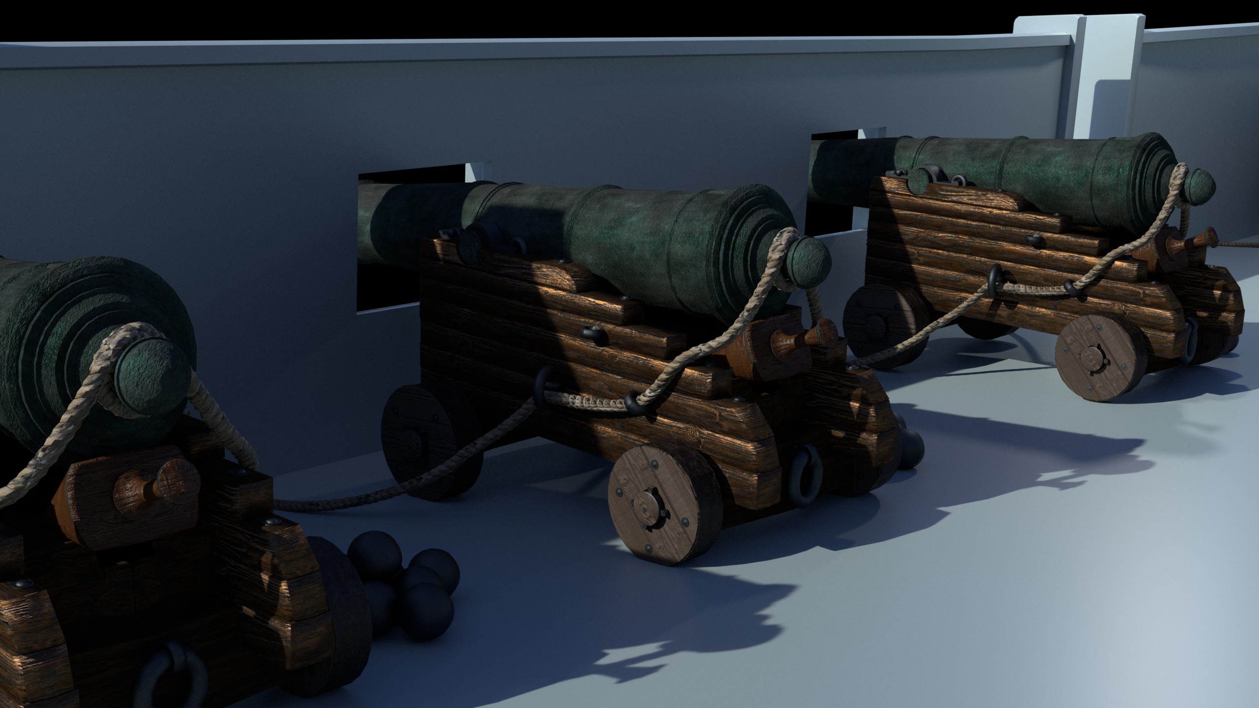
7 Likes
I’m really impressed! keep going!
1 Like
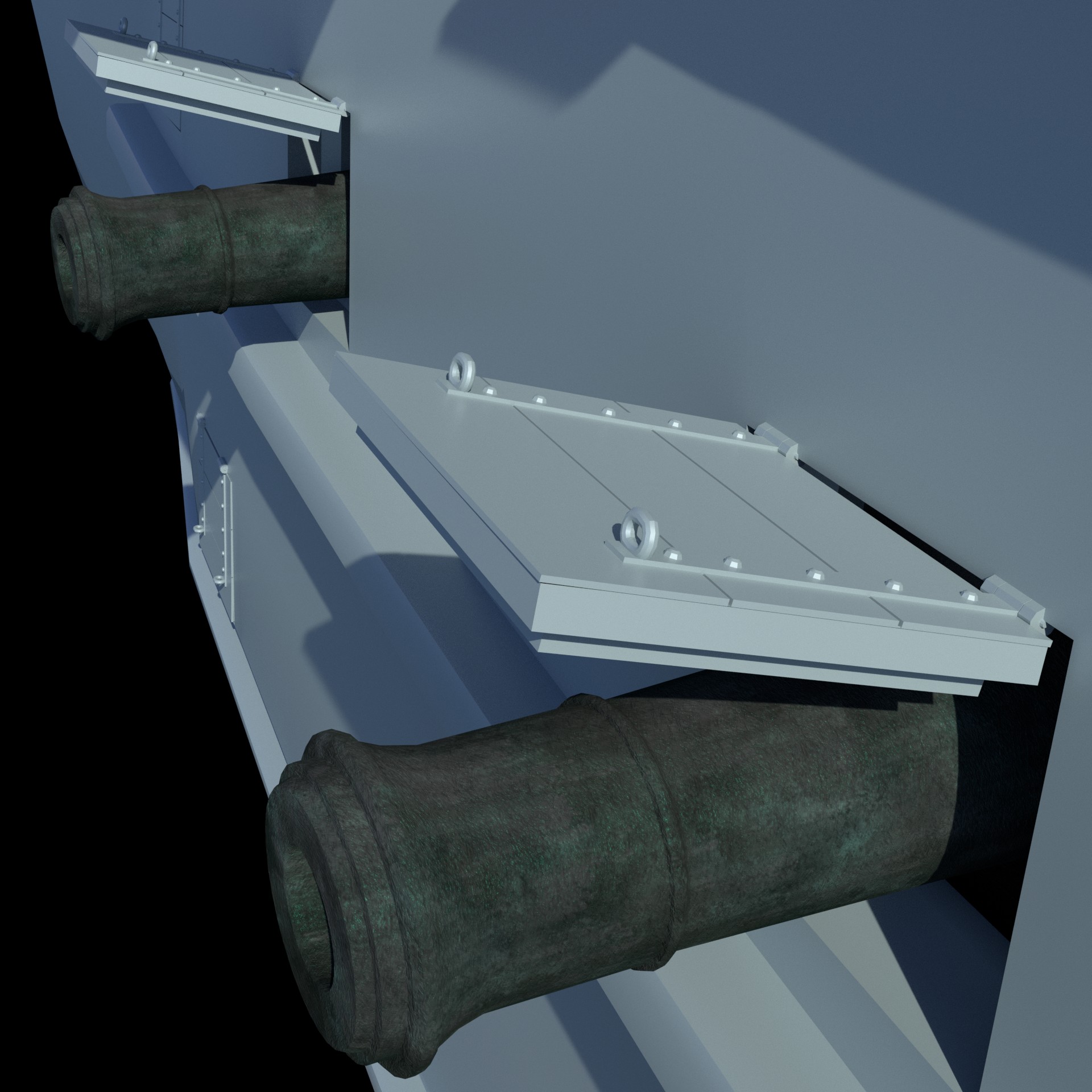
Lots of work put me on a pause with 3D graphics and this project. I hope I will have a bit more time now. I just created little bit of details, ropes, corrected some dimensions.
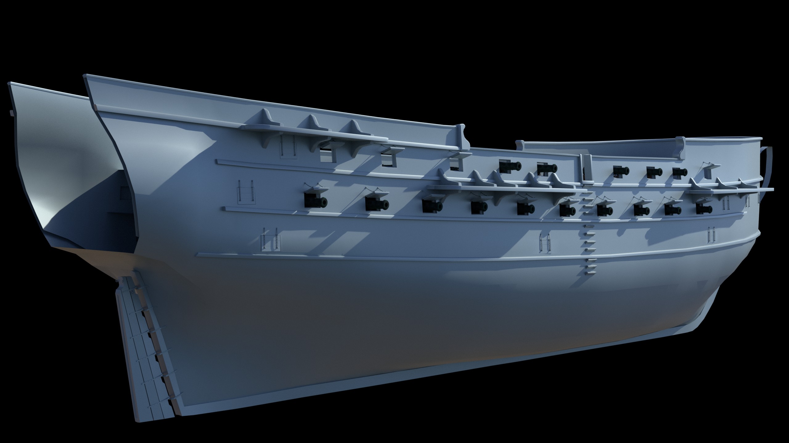

3 Likes
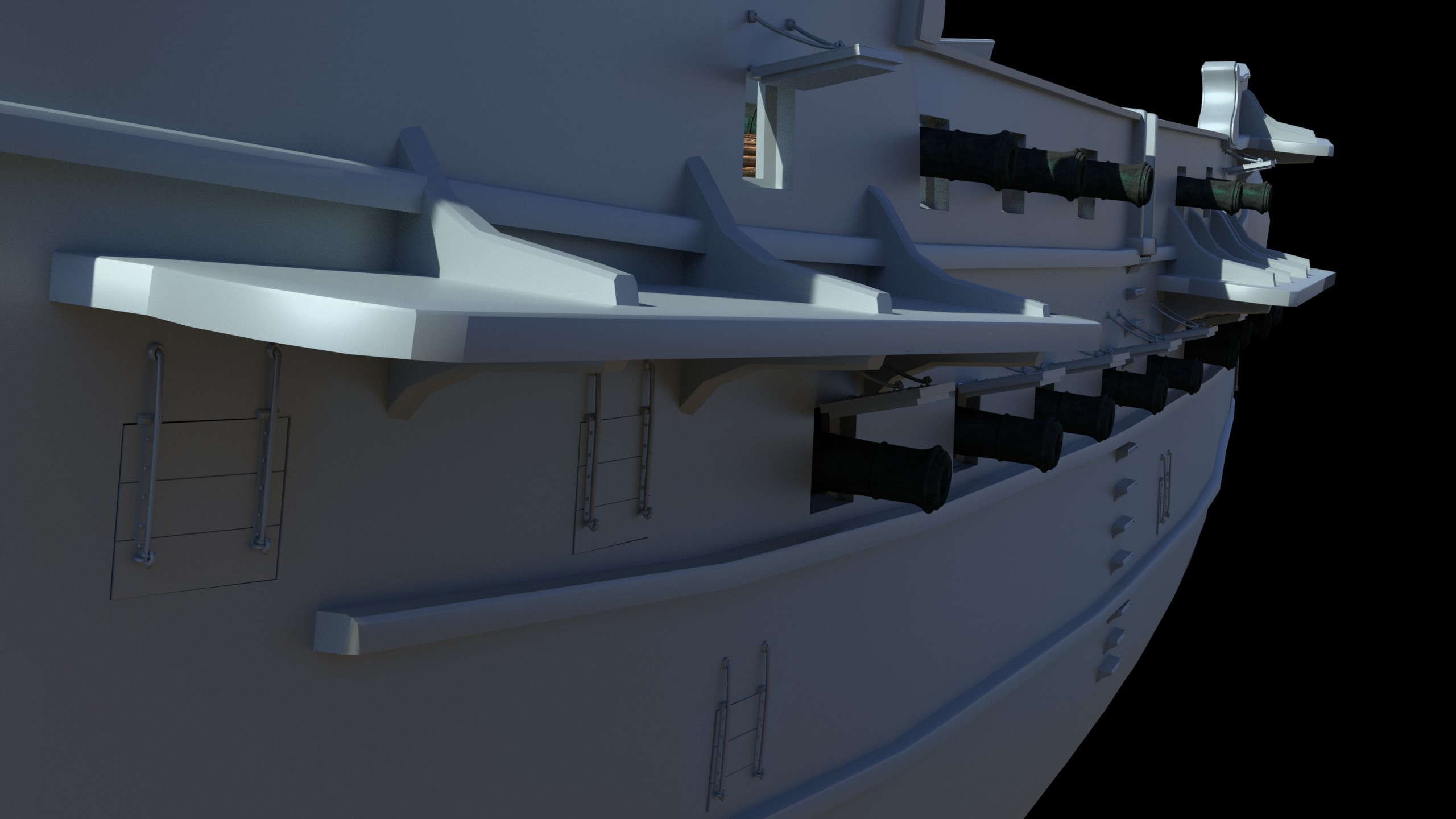
I completely missed your question about what are “channels” and “wales”. Sorry.
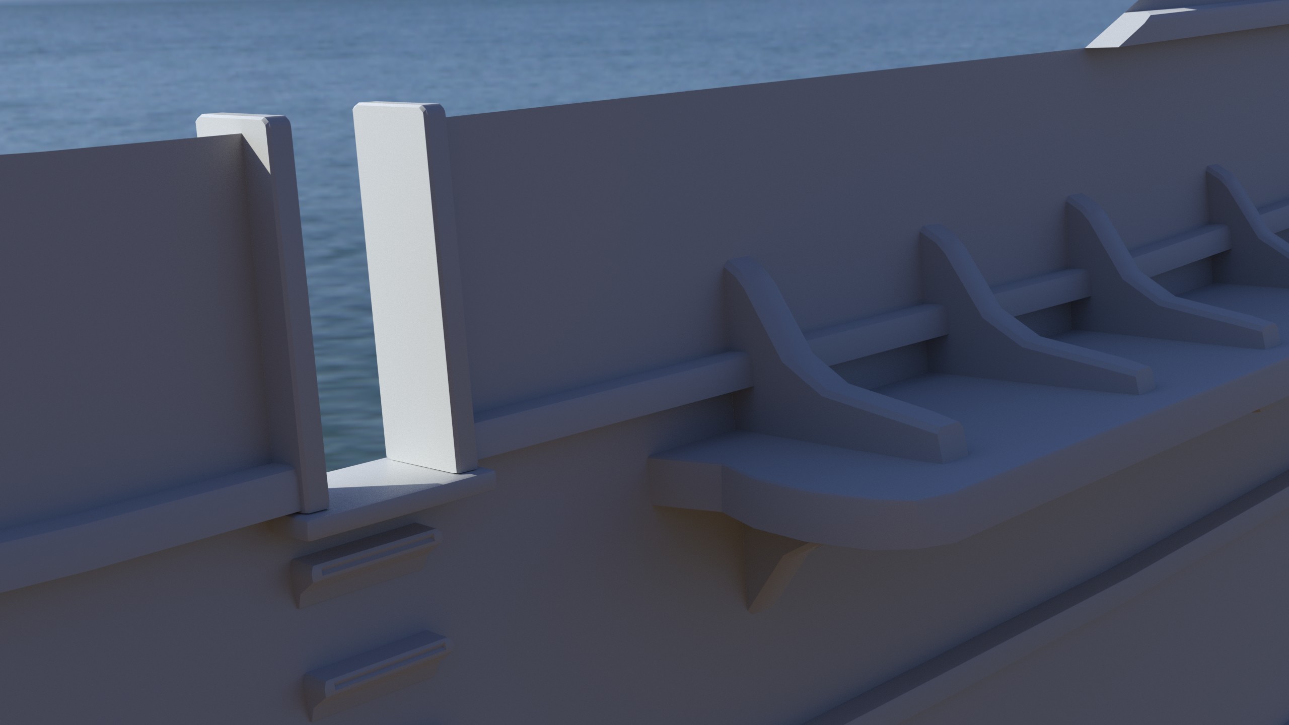
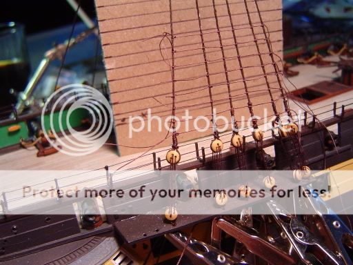
Channels are the boards that stick out perpendicular to the side of the ship. They are the boards that the rigging runs through on the sides of the ship. You can one of them in this picture of a model ship being rigged:
The wales are the thick planks that run the length of the ship. They are used to strengthen the hull and were usually made of large timber. You can see them as long black planks on this model:

2 Likes