My first post because I can’t get rid of this problem.
I have read endless equal topics but have found no solution till yet. Maybe your groupe intelligence can provide some input.
About me: I work as an machine engineer in germany and do normaly my jobs with Inventor, Solidworks, catia, NX, etc. But this is mostly special machines and manufacturing CAD, CAM, CAE. Because of the subsequent topic it seams that blender is the way to go.
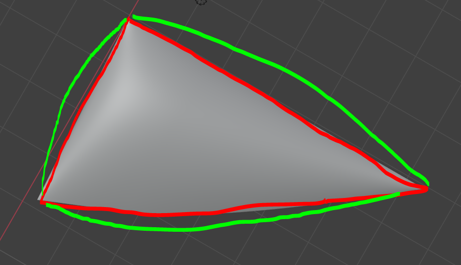
To create the freeform in reality we can print the uv on paper and cut them out. Glueing the two pieces on the coloured edges together → red to red, green to green, gives a natural curved form.
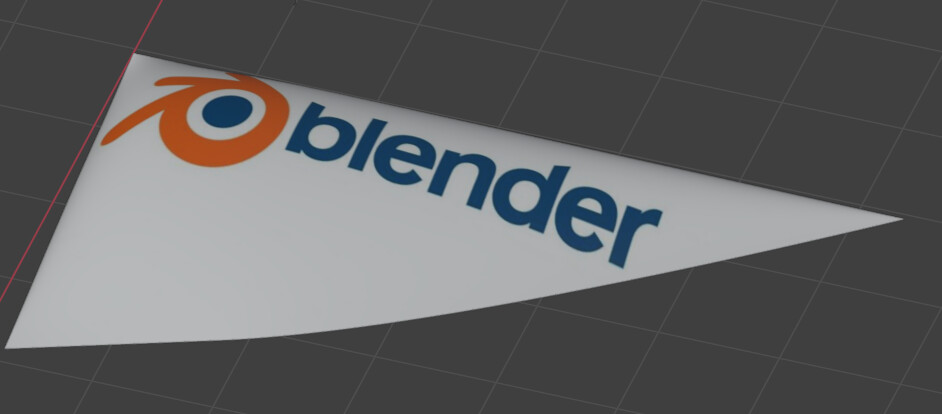
The paper should be painted with a graphic. For this I do texture paint on the mesh:
The Problem:
The question on this whole topic is how can I align the graphic to the edges of my 3d form precisely. Yet i can just rotate and scale the graphic freely but not fixed parametric. For example i want to have a perfect distance from the blender logo to the edges of the form.
a few unfinished ideas:
using texture coordinate node → but this uses the UV painting not the texture painting projection
create a new origin and orientate the texture somehow on it in texture painting mode
Special thanks to Jan Weiss from www.polyschubser.de because he had the basic idea to create the graphic pieces over the described uv workflow.
Do you need to have the mesh cutted in half in your UV space?
You could have the mesh cutted in 3D space, but still keep it ‘connected’ in the UV space (as long the red-green edges share the same UV space coordinates).
The idea is to create multiple uv pieces to avoid tension in the reality after glueing everything together. the unconnected uv pieces are necessary to have the forms of the pieces. (export them as svg for cnc cutting)
The main problem is that the uv looks like the green form and my graphic has the red form:
One with the distortion, that you can use for the cnc cut, and one without distortion that you could use for painting.
Blender lets you paint in one UV space, and then convert that paint into the other UV space (by baking). So you can jump from UV spaces as needed.
Think it as having two maps of the world, one in Mercator projection and the other as Behrmann… It’s the same world, but you can use the one map that fits better for a specific problem, and then transfer the result to the other map.
then putting the graphic to UV no. 1 and export the uv faces with the wrap graphic from uv no. 2. But how can i “burn” the grafic from uv no. 1 into the model to have it in uv no. 2 faces?!?
Now all you have to do is baking.
(you should read the manual about baking also, as i may miss some information).
If you already have a texture that fits UV1, then you need to bake it to UV2.
The baking is done by creating a second Image Texture in your material, with the resolution you want.
The final UV map (UV2) should be now the active one (the small camera icon in the UVmap list)… If your texture for UV1 in your material has no ‘vector’ input, it will default to the active UVmap, and you don’t want that, after changing the active to UV2. So you need to add a new UVMap node, pick the UV1 and connect it to the Image Texture node. (this will force that texture to use that UVmap, even if not the active).
With the new Image selected, change the render to Cycles, and Bake the ‘Color’ only. In the end, don’t forget to save the new image.
If you still find any problems, return here, and me or anyone else will be happy to keep helping you.
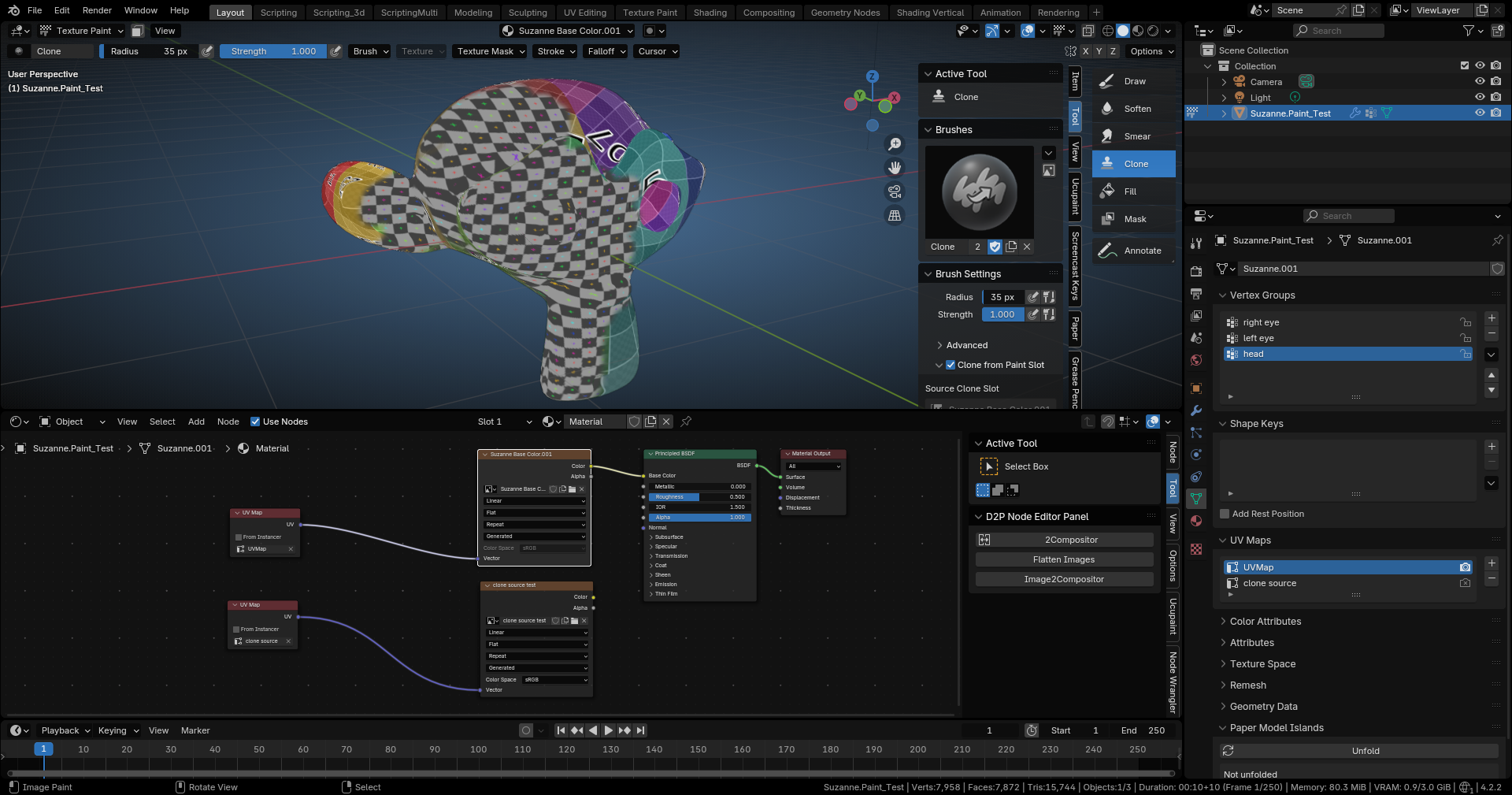
I know this is already marked as a solution, but for other possibilities I wanted to offer that the Clone Tool in 3d View Texture Paint can clone from slot, and in that slot in the node editor you can set an alternate UV to that clone source image. Just an alternate way to do it, that’s all. clone source separate uv.blend (1.2 MB)