Hi
I updated my VACGC project a bit.
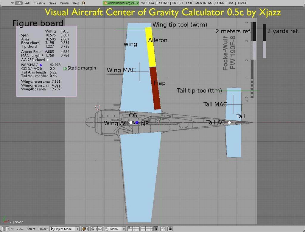
This script allow you to measure from the airplane drawing a certain key dimensions and calculate many others.
I aimed this for the fdm4bge plane creation, but it could useful for something else too.
(edit)
The .blend file contain now a instructions.
“”"
09.07.2009 Xjazz
Visual Aircraft Center of Gravity Calculator (beta)
This is beta state calculator is for the plane dimensions measuring and parameter computing.
User can measure & compute from the air-plane top-projection drawing/pic a following figures:
- Wing & Tail areas
- Wing & Tail spans
- Wing & Tail root/tip chords
- Wing & Tail aspect rations
- Wing & Tail MAC lengths & positions
- Neutral Point (NP) position
- Center of Gravity (CG) position by user given% or CG-object location based %
- Tail volume
- Tail arm
- Effective aileron wing area and arm
- Effective flaps wing area.
The figures are helpful for the plane specific flight dynamics model design.
Limitations
- Only traditional single engine nose-wing-tail airplane design
- Only non-sweep, rectangular or trapezoid wing designs
- Only non-extending flaps
Requires:
- Blender 2.49
- A script link on.
Instructions
IMPORTANT!
DO NOT SCALE OR ROTATE ANY PLANE OR MARKER OBJECTS IN OBJECT MODE!
Only the topic text and figure board can freely move and scale. The rulers object can only move.
1.Upload the plane top projection picture to the background.
NOTE! The airplane nose must be on left side and tail on right side.
2.Place the plane center line on picture carefully to the world x-axis.
NOTE! If plane center line is not level, correct this with GIMP or similar SW.
3.Scale the picture to match reference with 2_meter or 2_yards reference ruler object.
Note! The rulers are moveable.
4.In OBJECT-MODE move the wing and tail objects to proximate position.
5.NOTE! DO NOT CENTER THESE OBJECTS.
6.In EDIT-MODE move the wing and tail vertex’s to their position.
This is easiest to do in Wire-Frame mode.
7.If wing and/or tail has a rounded tip, then use a ‘wtm’ or ‘ttm’ tip-tool object/s.
This tool help the user to fine-tune the tip-area/s.
The tip-tool accept the half circle arc or smaller:
- If the tip-tool appear in green/narrow line, it’s INSIDE of the parameters.
- If the tip-tool appear in red/wide line, it’s OUTSIDE of the parameters.
NOTE! The wing and tail has own tip-tool and those should not mix.
8.In OBJECT-MODE move the aileron and flap objects to proximate position.
9.In EDIT-MODE move the aileron and flap vertex’s to their position.This is easiest to do in Wire-Frame mode.
After the vertex moving, go to the OBJECT-MODE and perform CENTER NEW for the aileron and flap objects.
10.In OBJECT-MODE user can move a black and white CG marker object and view how it’s effecting to the static margin value.
Optionally, in EDIT-MODE, user can give a desired static margin value to the green ‘p_cgli’ name text object. The CG marker object is moving accordingly.
BR
Xjazz
“”
Attachments
VACGC_05c01.blend (522 KB)
