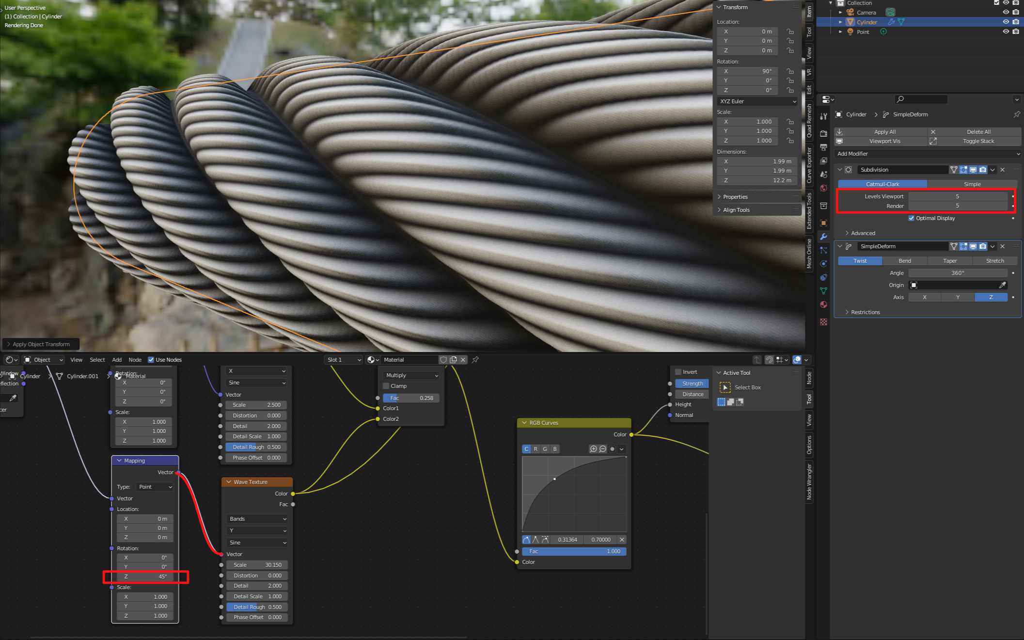
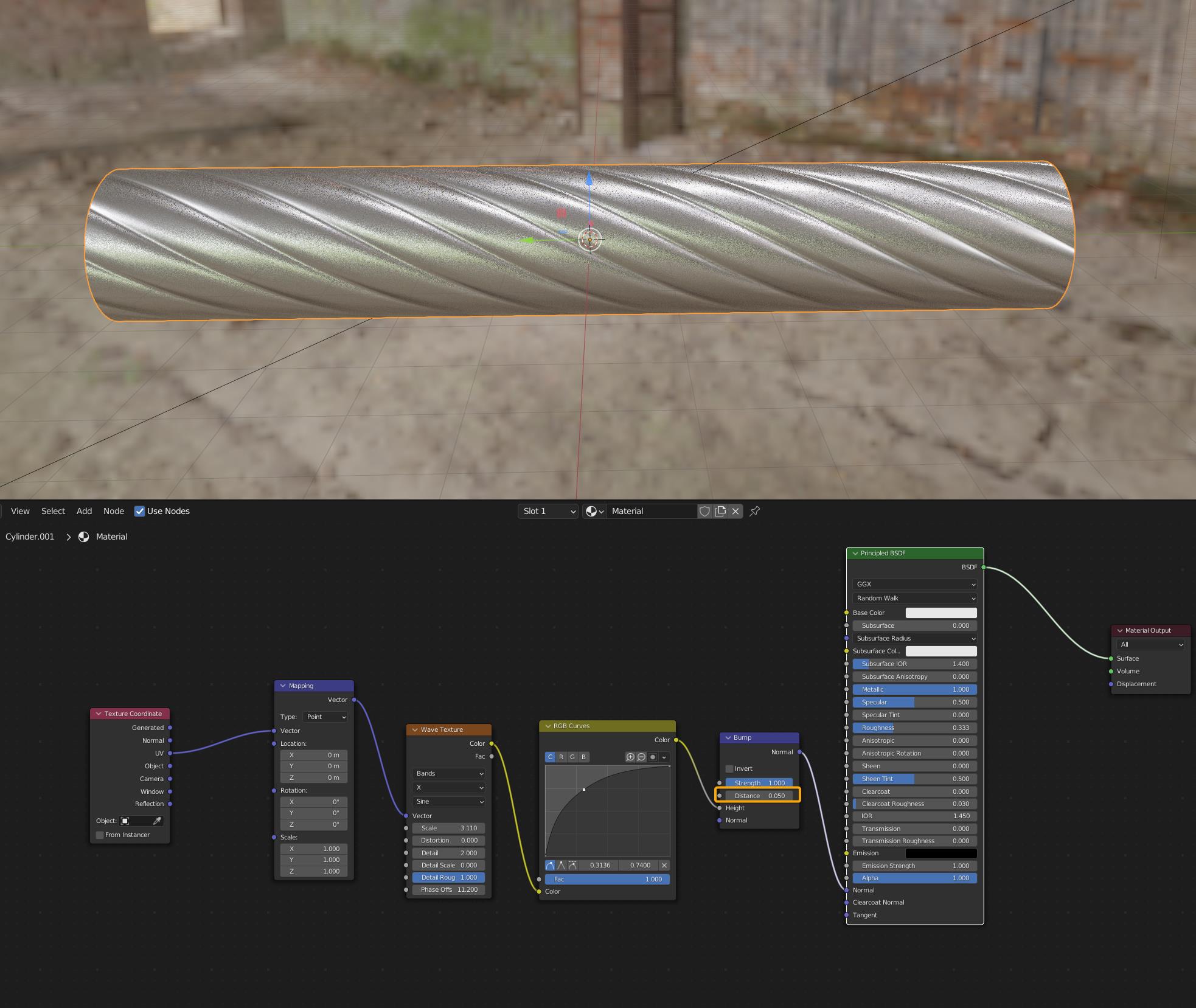
I tried to use a Wave Texture as Bump height factor and I noticed that it can’t be smooth even if the Output of the Wave Texture is made of shades of grey.
Thanks for your reply. I didn’t do it cause I didn’t want to change anything compared to the video (or I missed the step while watching it). Even with scale applied, there are still hard edges.
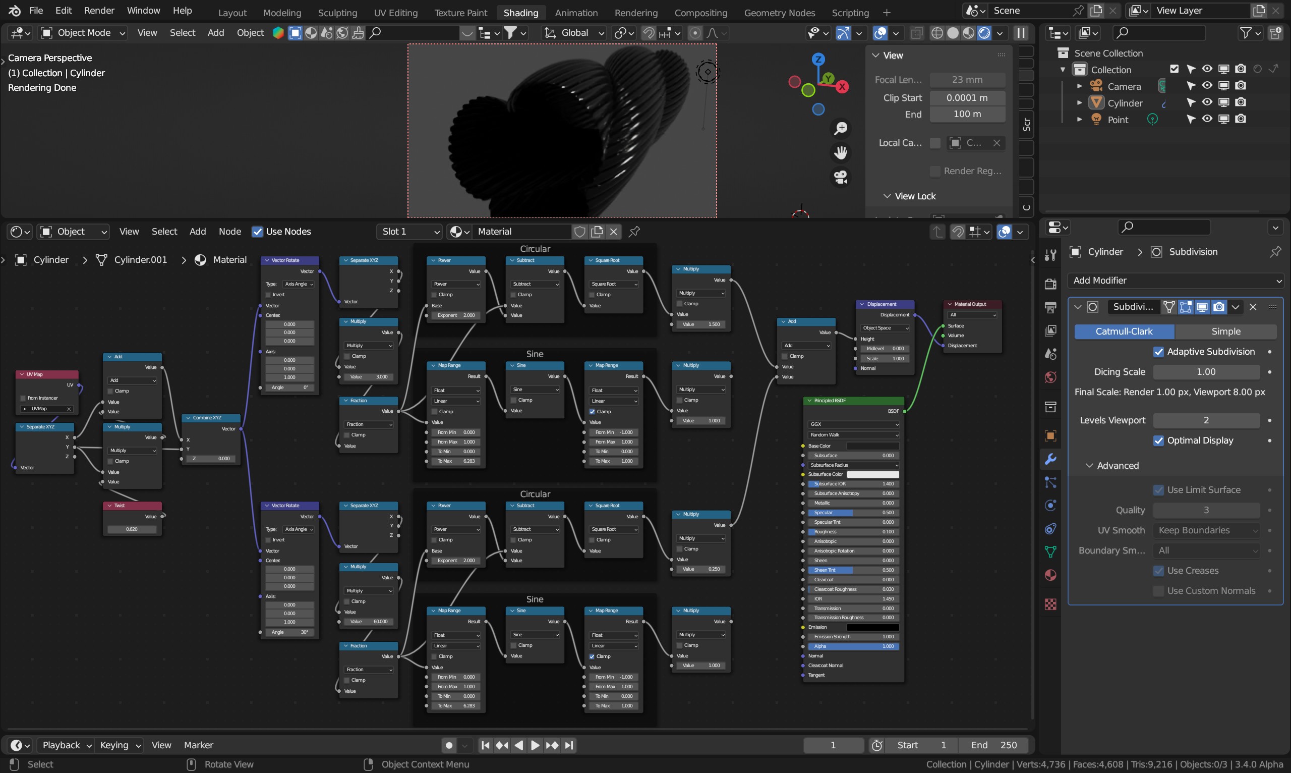
I believe I would plug the mini grooves into bump instead, as this kind of closeup I wouldn’t do. In that case, whatever goes into displacement scale should go into bump distance and leave the effect at max. I often verify the profile looks what I want it to look like using microdisplacement, then switch to bump later if I don’t need that kind of detail. I’m twisting the UV input using math instead of using a simple deform which can’t be used with microdisplacement. Sine almost never gives me what I want, so I’m calculating a circular cross section instead.
It’s another level here. Thanks. At first, I just would like to use a wave texture for Bump (no displacement) and thought the video would help me.
I let you another .blend file (the goal) where I don’t understand why the output of wave texture in viewer node is black and white with grey transition and why the bump is just 2 bands with no transition.
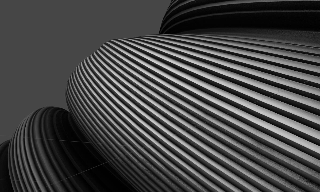
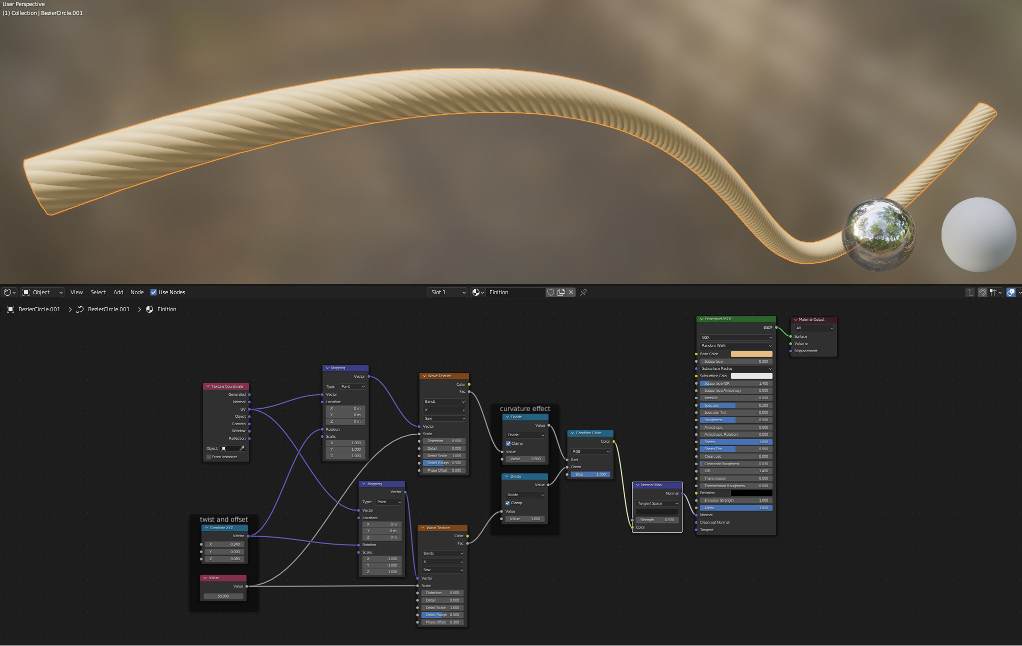
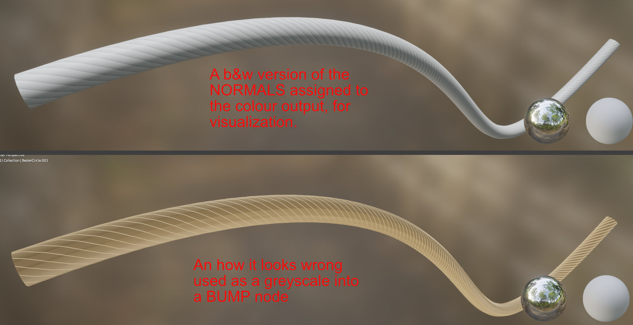
The issue is using a Bump node. These can only supply height information which is not the same thing as directional information which a normal map specialises in. On a rounded surface like your rope this is crucial as the curvature can be pointing in totally opposite directions for the same ‘height’ at any part of the rope.
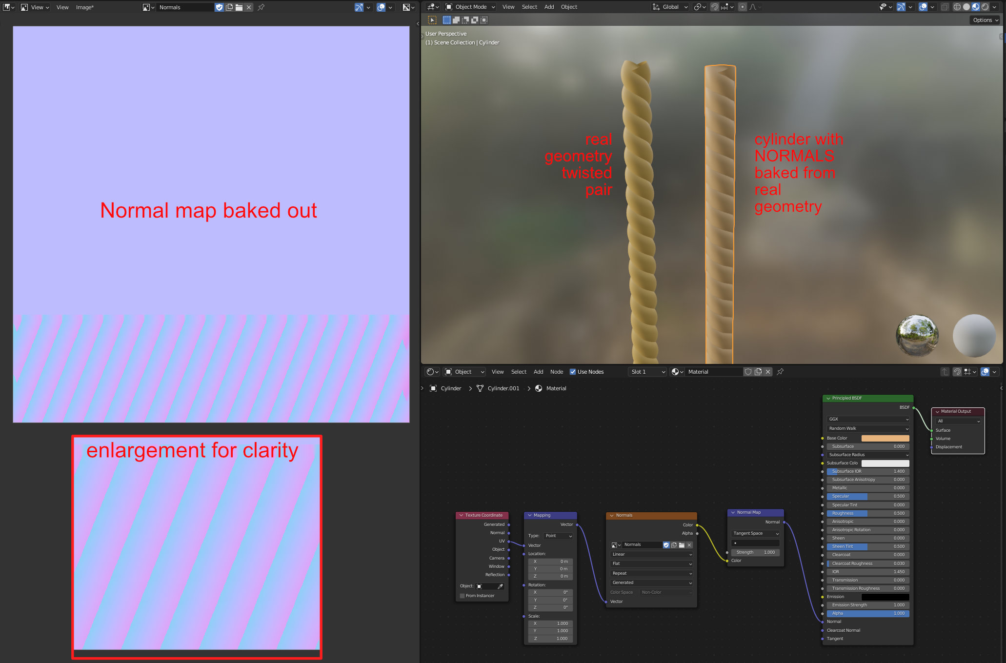
To solve this issue proceedurally it’s helpful to look at what the normals would really look like:
By-the-way, with proceedural texture on splines you’ll need to use UV coordinates as Object co-ordinates will move when the spline changes shape, which I presume you don’t want to happen. I’ve curved the rope to demo.
Thanks a lot Damian, I have now a better understanding of why the Bump node doesn’t work on a curve !
Really helpful. Thanks again for explanations and demo.
And thanks CarlG too even it’s far from what I can do and understand with nodes. I’m not familiar with the Converter → Math node and what you can do with it as excepted Add/Substract/Multiply/Divide, I don’t use other operations a lot.
Huh? Using a bumpmap the normals are calculated automatically rather than being looked up. Making normal maps slightly more efficient, but comes with other issues.
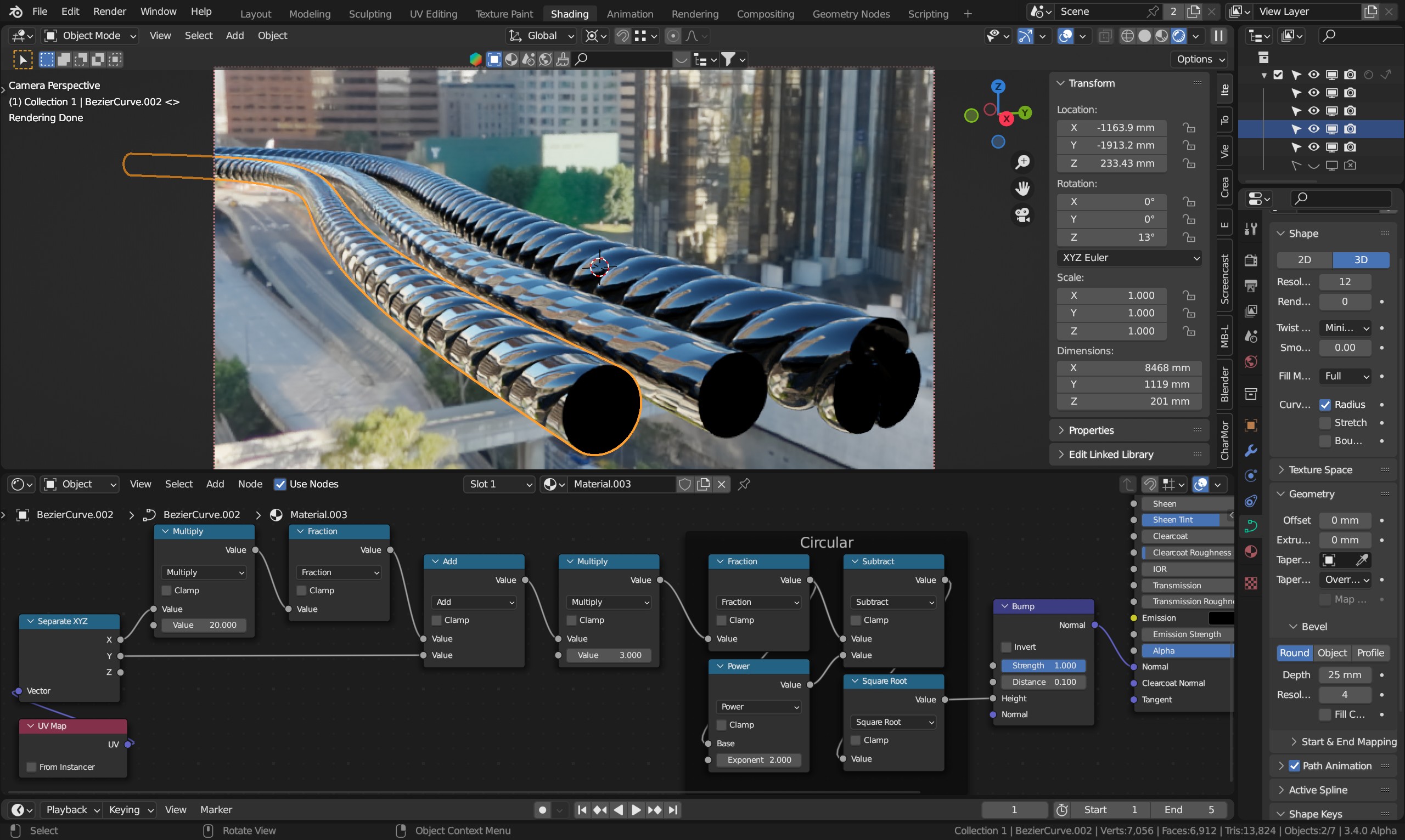
Anyway, here is a somewhat simplified version where only one axis is adjusted and used to give the appearance of a rope/cord:
Note that this is applied on a simple bezier curved (scaled up and scale applied, see dimensions). The highlighted on the left uses bump only, and has the same distance (0.1 in this case) as the real microdisplaced version on the right uses for displacement scale (midlevel 0). The center object does the same mistake as pretty much every tutorial out there - adjusting strength instead of distance - likely because the gradual slider control over it is preferred over the rough value control. That doesn’t produce even close to the same normals as real displacement.
The first multiply is just the number of twists along the axis, the second multiply is the number of “cords”.
I always asked myself when using the Distance slider cause in most cases, I can’t see a difference. I tried the previous setup with a lower distance and it works. Thanks.
happy to stand corrected, and that’s one heck of a node setup.
Here’s a comparison of all the methods, I’ve tweaked your parameters slightly to more closely match the ‘curve’ effect of the light. The differences are subtle, so @Manolo76 's setup probably saves a ton of effort given how minimalist it is, especially as it solves his use case. which is the primary goal.
Let’s just say I’m not on friendly terms with the wave node. It’s too easy to run into problems that can’t be explained or understood. I’m also not a huge fan of curves (float curve should have been used here over rgb curves, but whatever) or ramps, since the driving aspect of them - the point locations - cannot be driven externally.
In this case, what if I want real geometry using microdisplacement? You can’t have a simple deform/twist node after adaptive subdivision. I’m often using microdisplacement to check that what will become my bumps later on looks good without having any discontinuities in the math. For a twisted cable I’ll typically work with a simple curve rather than real geometry. Downside with microdisplacement is that it cannot be instanced, say far away in the scene from a source at scene origo.