Edit: sorry I forgot a crucial point. I am of course using a displacement map too. This question is whether the normal map should go into the BSDF normal map slot or the dispacement normal map slot. When using a displacement map along side, going into the displacement Height map (image in comments0
I’ve seen SO much conflicting information regarding displacement maps and normal maps.
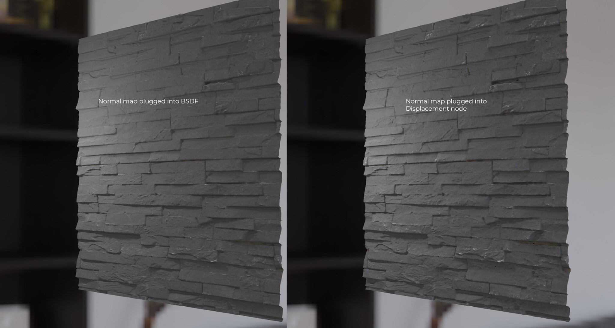
Most people say the normal map must be plugged into the BSDF and not the displacement node.
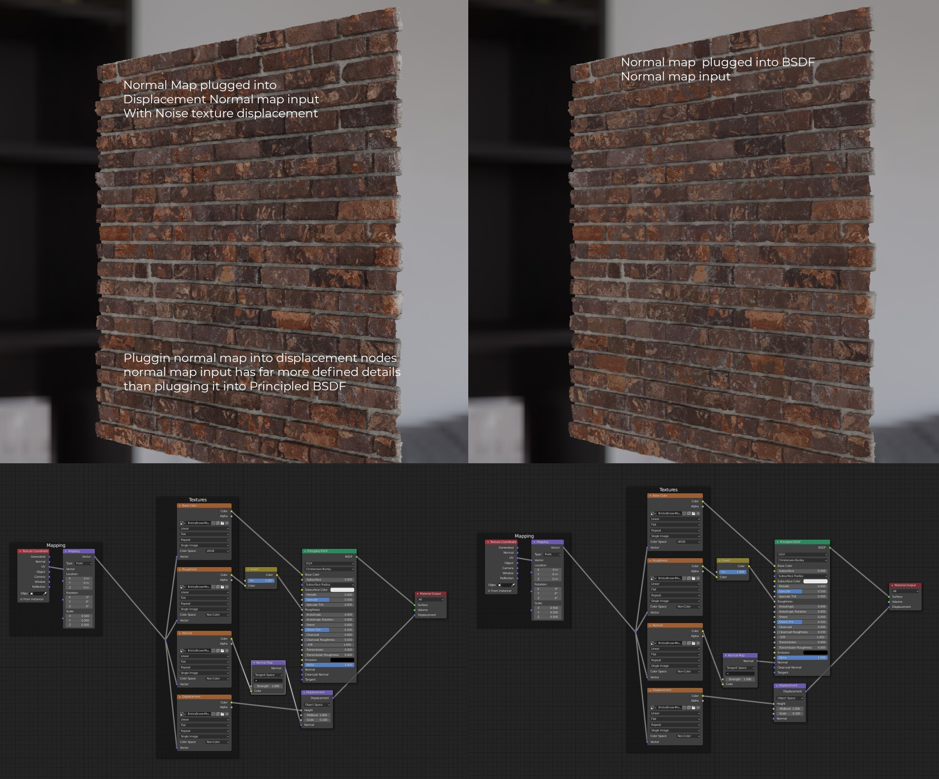
Here is a test with normal map plugged into the BSDF vs Displacement node (Displacement and bump turned on) You can clearly see the bump is far nicer and sharper with finer details when the normal map is plugged into the displacement node
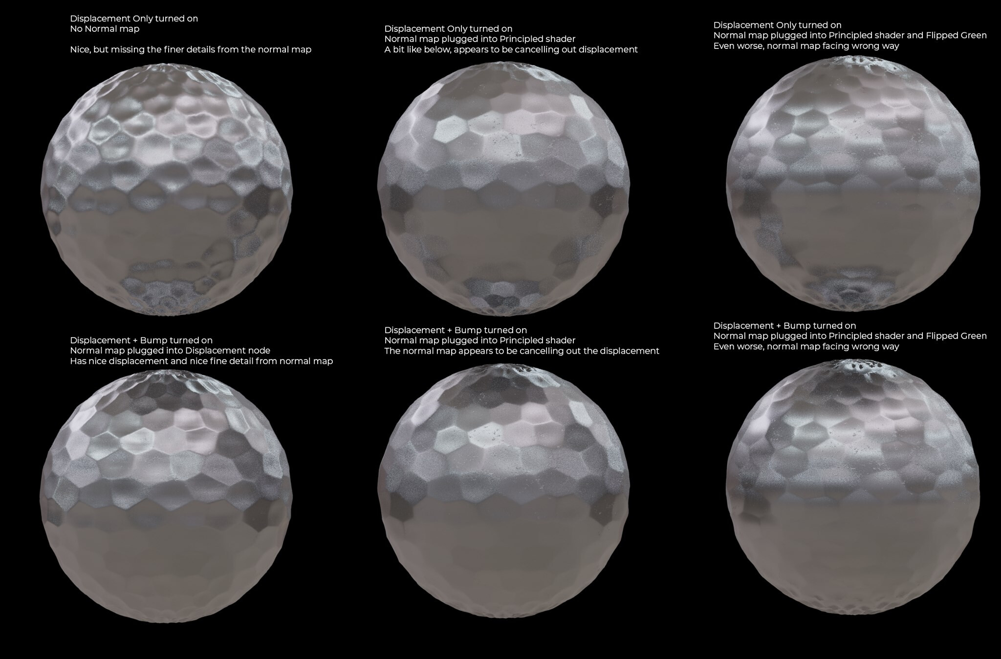
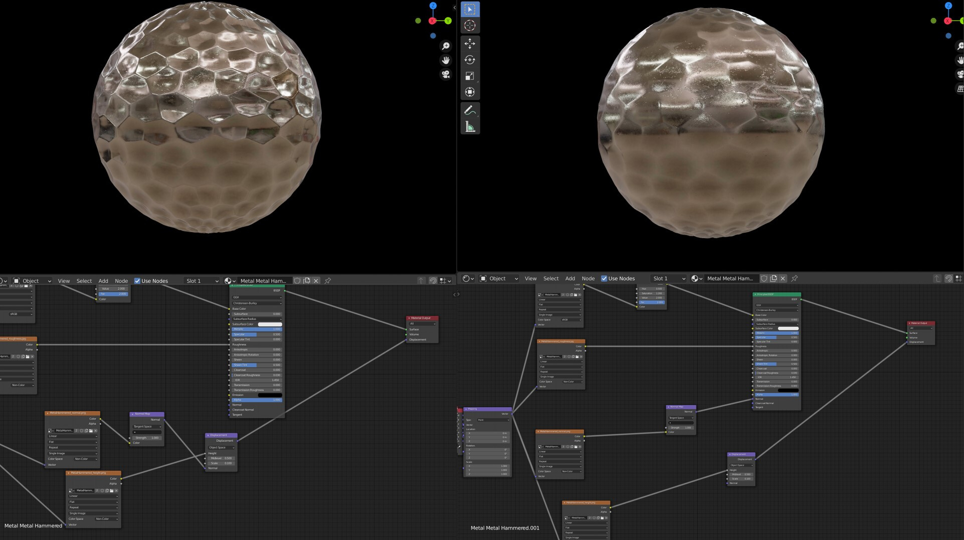
Here are some more tests. You can see BOTTOM LEFT with the normal map plugged into the displacement node, there is a nice displacement with nice fine detials from normal map.
If I then plug in the normal map to the BSDF instead, the displacement map appears to be less obvious and “flatter” - BOTTOM MIDDLE
I thought maybe the nromal map axis is incorrect so i flipped the green (far right) but that is totally incorrect
I know its not a big issue, if it looks better in the displacement node then that is great. But I just want to get a concrete answer if there is a 100% correct way to do it. Because most people say to put it into the Principled BSDF, which I believe is incorrect from my tests…
You are supposed to plug a displacement map into a Displacement node before plugging it into displacement socket of output node.
You are supposed to plug a normal map into a Normal Map node before plugging it into a normal socket of concerned shader nodes.
You are supposed to plug a bump map into a Bump Map node before plugging it into a normal socket of concerned shader nodes.
If you plug a normal map into a displacement socket, it acts like a bump map to modify shading and it displaces vertices of mesh.
Result is not as good as using 2 maps as they are intended to be used : A normal map to modify shading. A displacement map to displace vertices.
I plugged a displacement map into the displacement node and then the displacement node into displacement output.
If you plug a normal map into a displacement socket, it acts like a bump map to modify shading and it displaces vertices of mesh.
That is not what I am asking. I wasn’t placing the normal map into the displacement socket. I was using 2 maps. One is normal map and one is displacement map.
I’m wondering where do I put the normal map when using displacement. If I put it into the BSDF Principled shader, it does not look as good as putting it into the Displacement node. As in my example shows.
So is the correct method to put the normal map into the displacement normal map input? I only ask because most people say the normal map goes into the BSDF principled ahder normal map input but my test show otherwise.
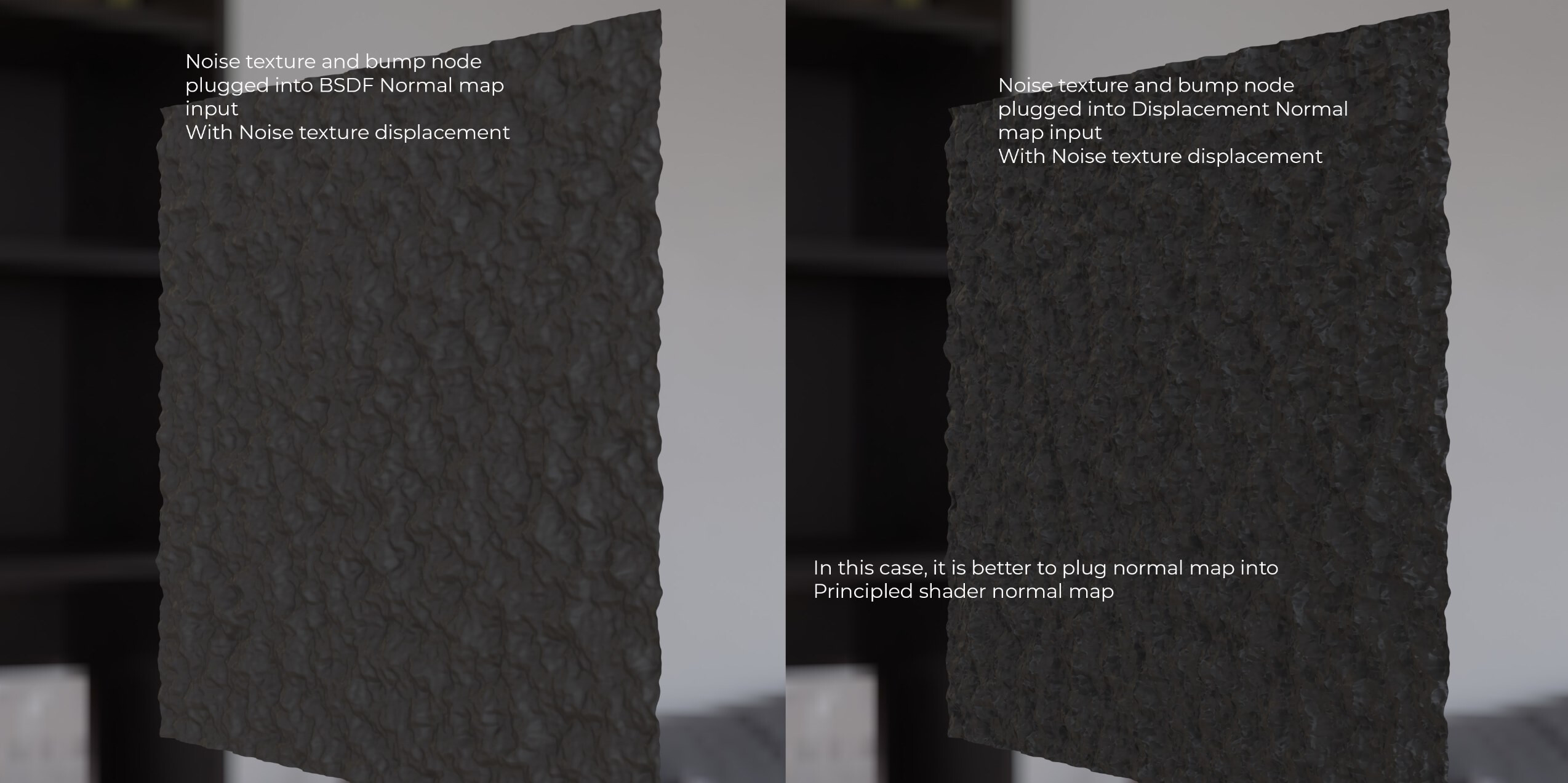
Here the exception is made when using a noise texture and a bump map plugging that into the BSDF Principled shaders normal map input, vs the displacement node normal map input
My guess is that it is related to the normal map containing more directional data than a simple noise texture and bump node
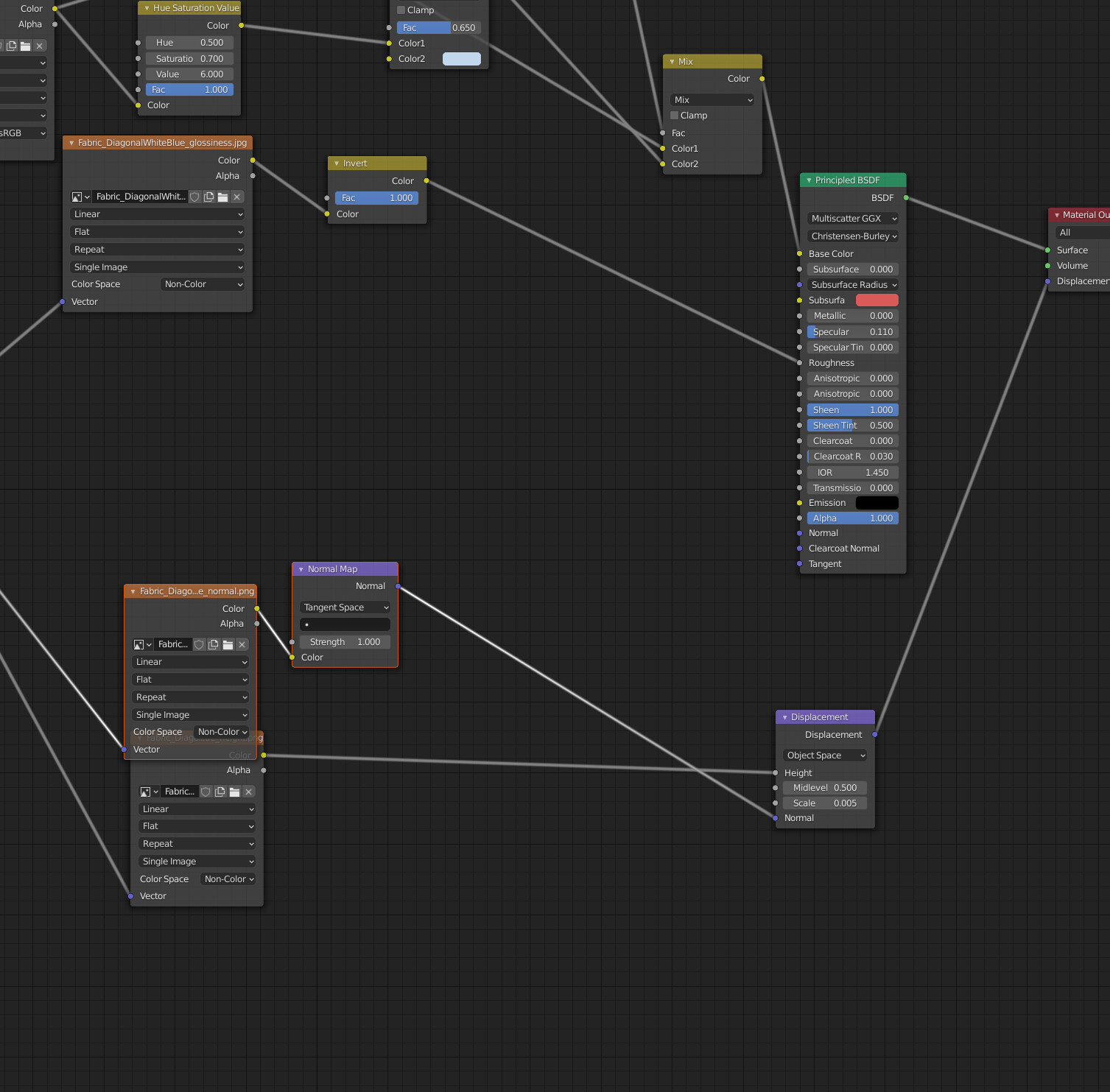
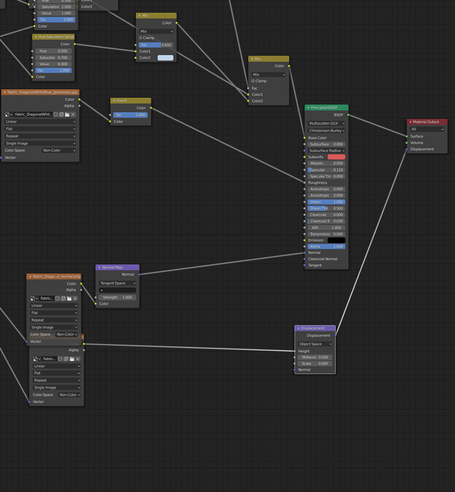
Here is another example with node set ups showing a normal map and displacement node.
Perhaps the more detail comes from the normal map pulling the displacement into other directions too?
When you use a displacement map to displace, you are supposed to pass Cycles into Experimental mode instead of Supported, add a subdivision modifier to object and use adaptive subdivision.
If you do that, you create geometry to displace. Plugging a normal map into normal socket of a Displacement node should mess-up displacement of geometry automatically generated that way.
If you don’t do that, impact of normal map on displacement map is just to improve final bump effect.
So, expected workflow is to use adaptive subdivision with displacement and plug normal map into principled shader.
The fact that you plug normal map > displacement node > material output node is equivalent to plug normal map > displacement node > bump node > principled shader, if adaptive subdivision is not used.
My guess is that normal input in displacement node changes the direction /vector of displacement from general vertex normal driven one to per pixel vectors from that normal input. With how displacement maps are baked usually it’s absolutely not necessary.
Using normal map together with displacement is kind of games tactic to make as less online calculations as possible. Usually it’s “displacement only” ( see in material settings ) for actual displacement and normal map for shading to Principled BSDF.
But you actually doesn’t need normal map at all and could use only displacement texture set as “Displacement and Bump” in material >settings>surface panel for both actual displacement and per pixel shading.
Using both displacement and normal textures is not making it better , it’s just less calculations online.
Adaptive subdivision or not it still needs subdivision modifier to make actual vertexes on surface to displace. (If I am not wrong)
Thank you, yes I think this is the answer. I think that the normal map is changing the direction of the displacement. I found that this may be what is leading to the finer details or the sharper edges at the corners. As if the normal map is “pulling in” the vertexes at those points.
I totally understand that is what using normal maps for along with displacement, its much less memory intensive too and less work for the computer (hence good for games). And of course if you just use displacement you need a very high subdivision count, which is where adaptive comes in.
I was just wondering why in some situations I was having better results by plugging the normal map into the displacements Normal input. I thought perhaps the normal map slot on the principled shader can be ignored and instead use the Displacement and Bump, with the Normal plugged into displacement like my last image on the left with much nicer details.
But I think think what is happening here is that the normal map is moving the direction of the displacement and almost pinching those corners making them appear shaper.