Whats causing this mesh mess

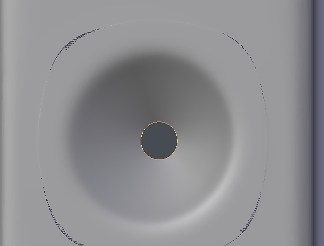
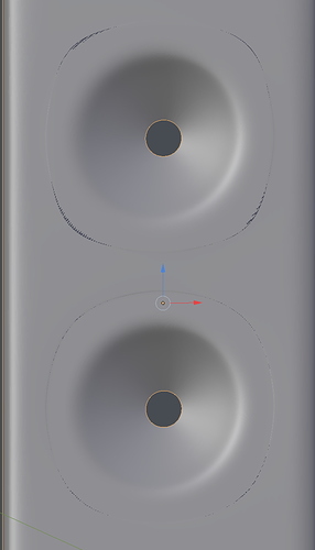
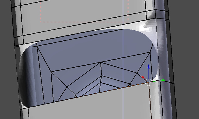
So I have modelled a hole in the bottom of my speaker, and then copied that hole and pasted it in the locations above it (2 times)… .But both the copied ones, have some black lining around it…so there’s something wrong. Im trying to figure out what. I think my topology of the circles might not be optimal… or maybe I havent put the copied holes in the exact same position as the bottom one (execpt for the change of height position offcourse)

ps… on further inspection…the hole on the bottom has the same problem (only lighter)…so it cant have anything to do with copying the holes… Cause that is the original…So it must be something with the topology right?

Anybody any insight?


Select everything in Edit mode, hit w, operation remove doubles.
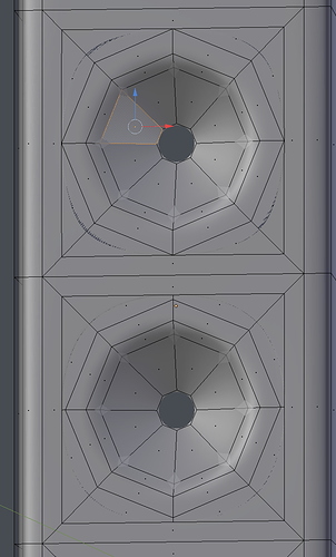
If that doesnt solve it it is most likely to the suboptimal way of connecting these 8-sided holes to the basemesh without respecting topology.

Hi, thank you for your reply…I already removed the doubles and that didnt solve it.
So yeah, youre right about the topology…

But im not sure what the optimal way is of connecting the vertices then. I noticed there are some very skewed rectangles… are those the problem? Can you help me on my way?

You should avoid n-gons with the subsurf modifier:


You have loose unconnected vertices. You need to model the surface in a way so it’s all connected if you wish to use subsurf on it. You could add loops from the sides and in the middle, so the vertices have matching ones in all the pieces and the remove doubles(edit mode->select all->w->r or type remove doubles in the space bar meniu)

Thank you for your reply… is there any way to filter out and show all the loose vertices? I can’t find them on first glance.
If i know where they are, I will use your method to connect them.

Nope, the artifacts are not due to unconnected vertices, rather to the surface overlapping because of n-gons.
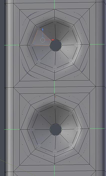
If you look at my previous post you could see where edge loops have to be added to fix (green lines)

paolo

Yes, indeed. This seems more likely. I am a bit puzzled how this geometry was modeled. It’s usually easier to just have the loops there in the first place.

He explains that he duplicated the ‘holes’ and put them in place, I suppose he just connected their vertices to the existing geometry, thus making those rectangular n-gons all around (they appear indeed as rectangles but they have 5 vertices).

So that’s what I thought, but in that case the vertices on the sides and in the middle would not be connected to the edges but they seam to be.

Why, perhaps he simply hit F key and filled them.

If you upload the file people will literally be able to fix it within seconds.

yes that is exactly what I did haha… I take it that’s not the way to do it?


ok so i made some parts again and started to join them to the exsisting rectangle… Its better now (next time ill start the mesh from scratch again)… but this part is still not working for me (see picture)…

I just want it filled and in line with the rest of the shape… But when I fill it (select vertices and hit F… but I think thats not the proper way.)… the mesh bends all wrong and looks weird… That right side seems to be the problem…but in my eyes its identical to the opposite side…

So if anyone can tell me where the fault is… (i know the topography is faaaaar from perfect)…

Or here’s is the file if you want to help me out…

I didn’t mean that it’s not the correct way, I just tried to figure out what you did and how you missed to create the proper edge loops.

What matters here is to understand what caused what, and as a general rule n-gons should be avoided whenever a subsurf modifier is involved; also triangles can generate artifacts on subdivided meshes and should be avoided, but that’s true mostly for organic forms, while on flat surfaces they are often not harmful (there are exceptions also on organic meshes, where in the proper place they can even be useful, but these are corner cases, the general rule is no tris, no n-gons).
Sometimes, as in this case, n-gons can be difficult to detect, so I suggest to occasionally run the command ‘Select Faces by Sides’ (greater than: 4) to discover them.
Another useful thing to do is to temporally activate the visual display in edit mode of the subsurf mod (by the icons in the modifier on the Properties area), so to see the geometry in its deformed state.

paolo

I would recommend learning all the tools for polygonal modeling. Look through all the functions in the w, ctrl+v, ctrl+e, ctrl+f (all in edit mode) menus. Also have a look at the F2, Loop Tools and Edit Tools2 add-ons that can be enabled in the preferences - they may or may not be of interest to you, but you should definitely be aware of them. I think you should go through the menu functions one by one and ensure you understand everything there is to understand about every single one of them. That’s basically all that there is to modeling. That is not an extremely hard task to do but it will clarify a whole bunch of things.

Yes and how to merge vertices, the different way of fill, connect edges ( grid fill, bridge edge loop etc…) ., knife tool…

I will say that for each case, there’s a function but there’s offtly many different ways of doing the same thing. It is nice to get a good amount of knowledge about all the features, this way, it start to be really more easy to get the whole pictures and get different solutions in hand.

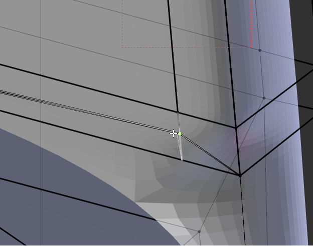
You have at some place some error like on the screenshoot , you have an long edge who is then coverd by 2 small edges. as example.

Dont worry, this are standard error when starting with this type of software, if you have a doubt, just try move some vertices and see what happend ( shift+v).


hence corrected you can connect the edges correctly.

I have do a quick correction, but i have not really the time to check all.

[ATTACH]506064[/ATTACH]

  • You have all edges with “edge crease” at 0,0034… hence why the edges are so thick. select all and remove it in the right menu…

  • I have reconnect some edges and remove some in the vertical, who was not needed, ( in addition, i have recreate quads in the center of the speakers, like that theres no deformation there )

And second thing, its better to work with the object straight, then you can give it the correct angle when it is finished ( and dont forget to apply scale and rotation ( control+A ) )

(edit: just have seen sourvinous look to have fix all problem on the file, so i remove mine ).

There were some degenerate faces and some redundant vertices, the geometry is rotated (in edit mode) respect to the object rotation (I did not fix it), some misalignments and other things, difficult to explain, it would have been easier to redo from scratch than to fix.

Next time try to be linear in your workflow, one step at a time, following the rules; with practice you will learn, I’m not able to be more instructive, sorry.

EDIT: and follow MartinZ’s and Lane’s suggestions!

Here’s the file corrected (I hope :)) speaker_online.blend (2.67 MB)

paolo

I can’t thank you guys enought. I have been around software for all my life, and I just started with Blender… But im very very impressed with this communicty. Its like nothing ive seen before, such a helpfull community. Thank you for that.

I will definately take your advise and start reading and learning more about the basic of modelling and all the functions involded.

Thanks again for helping me out and solving this for me.

only thing i need to fix now is my origin point…that is still rotated and not aligned with the axis… How can I reset it so its aligned with the axis again?

The first thing to learn in blender is the difference from Edit and Object mode.

while in object mode you move/rotate/scale the object respect to the world (or the object parent), in edit mode you work directly on its geometry, that is vertices, edges and faces.
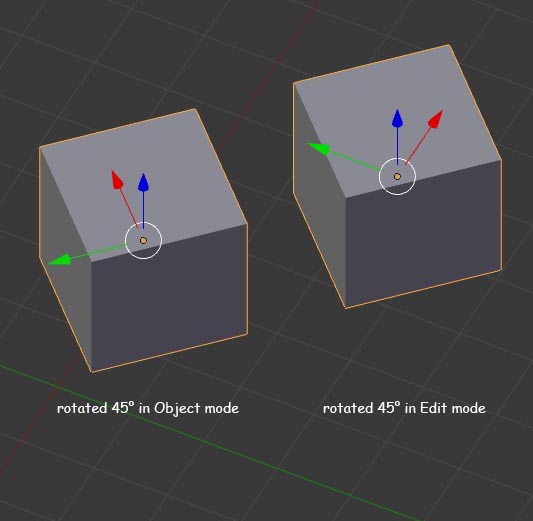
The consequence is that if you, for instance, rotate the whole object in Object mode, you are changing its ‘object matrix’ and on the N panel or in Properties area ->Object you can see how its loc/rot/scale are changed; consequently you can always reverse these changes, and in ‘Local Transform Orientation’ the axis will be oriented like the object is.
If you move/rotate/ scale the components in Edit mode instead, the object matrix doesn’t change, only the relative positions of components respect to the origin and axis of the object are modified, and hence you will not be able to reverse these changes.

Please, don’t refer to this bad explanation of mine, look at the manual instead for a correct learning:Blender Reference Manual — Blender Manual


as you can see in the example, the cube rotated in edit mode doesn’t have its faces aligned with the object axis any more, and you can’t realign them unless you remember exactly what you did.

In your scene the object was rotated both in object and editing mode and it’s not easy to realign its components.
One way could be:
• in the viewport header choose ‘Normal’ as ‘Transformation orientation’
• enter Edit mode and select a face you want the new axis to be aligned to
• in the N panel go to ‘Transform Orientation’ and make a new custom orientation (the + button) then in the viewport choose the new created orientation as ‘Transformation orientation’
• in Object mode, make a new mesh object (whatever), enter Edit mode select all and delete all its vertices (now the object has no components)
• in object mode, the new object selected, from the ‘Object’ menu choose ‘Transform’->‘Align to Transform Orientation’
• in Object mode, select the original object and the new created object in sequence and join them (Ctrl+J): the first object will be incorporate into the second one with the new Local matrix.

Note: To save Materials, Modifiers, Constrains etc. of the original object you can simply duplicate the object and delete its components, instead of creating a new one to join to, this way you’ll also have the origin at the same position.

Try that by yourself, and if you have problem let us know

paolo