Working with driver and calculate an angle between x and y location

Hello all!

First I want to apologize for my being slow and low at math as this question likely involves.

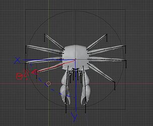
I made a crab that I am wanting to animate through drivers.
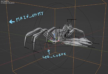
The crab is moved through an empty that is labeled Main_empty.
There is a basic driver to animate the movement of the legs following a curve labeled Leg_curve.

When I move Main_empty on the y axis, the driver works properly and the leg moves alonside the Leg_curve.
Although, I had liked to push the animation further, so that when Main_empty is moved along the x axis or on both x and y axis, Leg_curve would rotate on the z axis accordingly.

To explicit the idea, it would look like this if movements are only along one axis or the other:

if Main_empty moves on y = Leg_curve on z (0°)
if Main_empty moves on x = Leg_curve on z(-90°)
if Main_empty moves on -x = Leg_curve on z(90°)
if Main_empty moves on -y = Leg_curve on z(0°)

Although, how to calculate Leg_curve z angle when Main_empty moves on both x and y?

I gathered that the equation would be the following:

tanθ = y/x

But if I comprehend it well, this equation is only valid with fixed positions.
And here we are dealing with vectors(if I am correct).

Then the questions would be:

  • how can I turn x and y location for Main_empty into vectors
  • how can I calculate Leg_curve angle from the obtain vectors
  • additionaly, is it possible to implement the equation directly as a driver or would it need other wizardry?

I gather this ‘simple’ idea might prove more complex than I imagine, as in requiring some notion in Python (which I can only vaguely read) and math.
But any hint welcomed! :slight_smile:


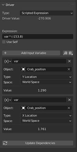
As an addendum, I am using drivers to animate the leg of the crab.
I am having an issue as onyl the lowest (latest?) input variable is taken in account.
Here that would be the x location. So the driver only works when the Main_empty is moved on the x.

Although, I can see that there is a ‘value’ being calculated for y too but it isn’t reflected visually.

Is there a way to apply the expression for both x and y location at the same time?
image

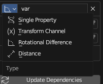
use rotational difference to get your angles

and

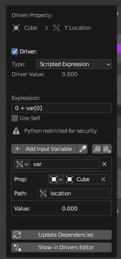
Just not sure how to avoid the ‘restricted for security’ stuff.

1 Like

Awesome! thank you.

1 Like

Hello,

Thank you for your answer but I am not sure I understand the logic behind it.

I cannot find a proper documentation on how to use the rotational difference, but from what I understand, it only gives an angle from already existing angles.
Let’s say, the difference in angle between x and y empties.

But in my case, I am interested in calculating an angle from x and y locations, not from rotation.
So that if I move the crab in a direction x + y (hence location_y and location_x) how can I find the angle of the direction?

So it seems your answer doesn’t respond to my question, or it is and I am not getting it? :confused:

I’m afraid I don’t really understand the ultimate goal, but maybe I can still offer some help on various details, that might help you along you way to your ultimate goal.

To talk about angles, we need two vectors. A vector is a start and an end; the start is implied by it being a vector, the start being 0,0,0. So to find an angle between two vectors, we really need at least three positions: the origin of the two vectors (that 0,0,0 point) and then two different positions, each composed of X,Y, and Z values. In some cases, the two vectors we’re interested in might have different origins, so we’d need four sets of triplets in that case; we can see that a vector going from 1,0,0 to 1,1,0 has a different angle than one going from 0,1,0 to 1,1,0.

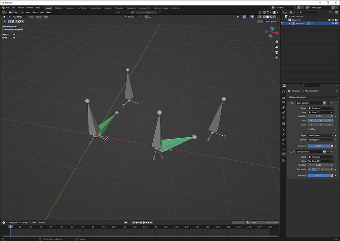
If we have these positions, we can make bones that create those vectors, from those positions. We could make two bones, with identical rest-pose axes, use a copy position constraint to acquire the position of the origin (maybe shared, maybe not); we can then use a damped track constraint to acquire the direction toward another marker. We can then compare the rotational difference of these two bones to get an angle between them. (Technically, we might want to stretch-to instead of damped track to acquire a vector with the proper length, but we’re not concerned about length here.)

Note, these aren’t deforming bones; these are mechanism bones, that exist just to do some calculations for us.

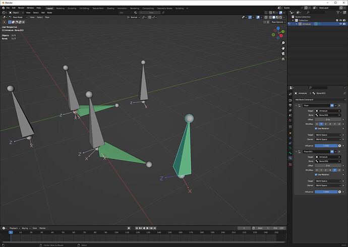
If we are concerned only with the angle of the projection onto a plane, we can use a pair of floor constraints to constrain the targets of the constraints to a particular plane:

Here, the target of a damped track is itself constrained to a particular plane; I’m using a new bone to define that plane, defining it as the XZ plane of that bone (flooring to 0 in its ±Y axes.) We’d want to do that for all origin and destination markers for the vectors.

This is possible with pure math, but I find it easier to let my constraints do my math. It always takes me longer to try to figure out a trigonometry problem, and whenever I can let constraints solve a problem or part of it, I let them do the work.

Right-- you’d really want θ = atan(y/x), because you want to solve for θ.

This is valid for variable positions; that’s why it uses “x” and “y”, to indicate that those can be any values. However, it is a 2D equation, and there are times when it’s invalid (when the vector is not unit length, or when the angle is outside of -90,90 degrees.) A better function, useful enough that it gets built into a lot of programming languages including Blender’s Python, is atan2, which works for all ranges of angles and all lengths. Keep in mind that this is not the angle between 2 vectors, but the angle between a single vector and the +X vector. To find the angle between 2 vectors, you’d have to subtract one vector’s atan2 from another vector’s.

(and in any case, vectors vs. fixed positions isn’t really the right division to draw; a vector might be fixed or variable; the world +X vector is about as fixed as anything could ever be considered to be.)

1 Like

Bandages essentially elaborates more on it. I’m not sure what exactly you have to do in your case with it as I’ve never automated hexa/octopod limbs myself but generally speaking, instead of doing some manual pythagoras, you want to set up a rig that can use those driver variable types in some useful way. So yeah, all my answer answers is how to get angles or access location vectors :slight_smile:

Thanks to both of you for your answers :slight_smile:

Sorry I got caught up in other things and haven’t wrapped my head around your proposed solution yet.

For the time being, here is a video that hopefully better explicit the desired result.


Sorry for the typo in the vid, but the curves that are supposed to rotate on Z are the one to which the last leg bones are constrained to.

Hopefully, that’s better!:slight_smile: