Hi,
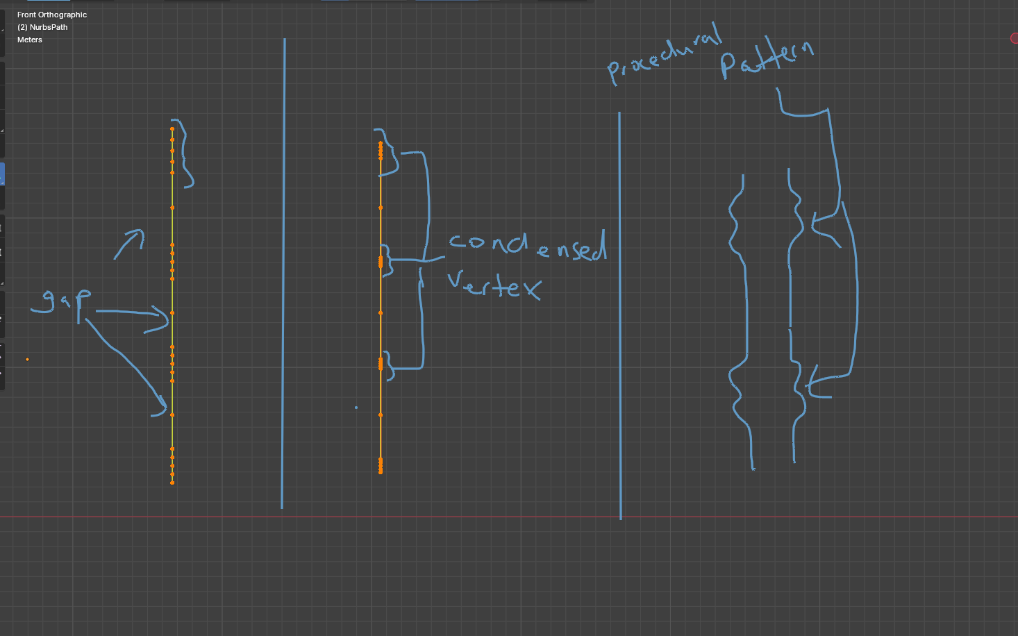
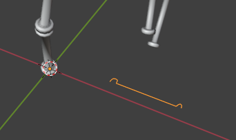
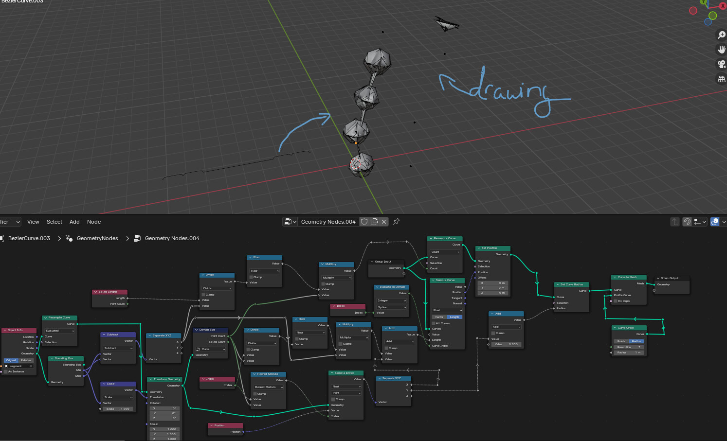
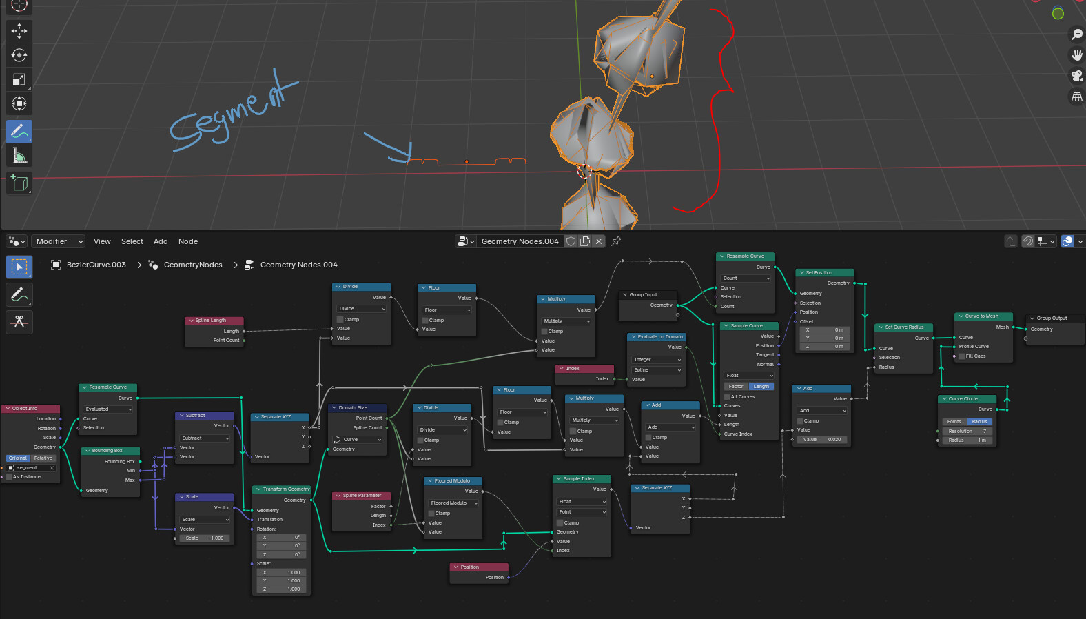
I have a curve that alternates between regions of higher vertex density and regions of lower vertex density. This pattern is controlled using Geometry Nodes in Blender 4.0.
My inquiry is whether there is a method to compress the regions of higher vertex density, depicted in the screenshot, while maintaining the gap between them, and additionally add a profile using a curve circle to create raised areas of the denser vertex concentration, as illustrated on the far right side of the screenshot. Ideally, the last part should be achieved using a Float Curve node.
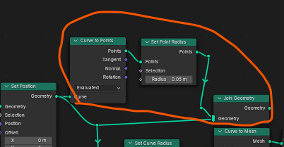
Here I’m doing just that… Driving a Set Position node off of a Sample Curve node which is using another 2D curve as a sample source for some more advanced modulo math…
…so, are you sure you want to do it this way? You can make your life easier by just using a Array/Curve modifier combo. Why not do that? What is your goal?
This looks exactly how i needed it, but unfortunately i can’t see the nodes when i zoom in
May i ask you for a more clear picture?
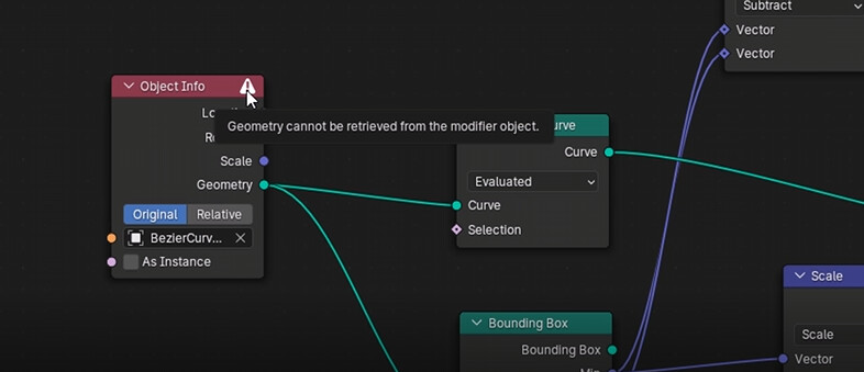
And is it not possible without transfering a modeled meshed information through object info node? It looks like you shaped a mesh before and used the object info on the far left of your node tree to transfer mesh data?
If not, what data is transfered in your node exactly?
And could you explain me what exactly sample curve node is?
It’s hard to say without seeing the full name of the Object, but it looks like the Object Info here refers to the same object you’re modifying instead of some other curve, hence the error.
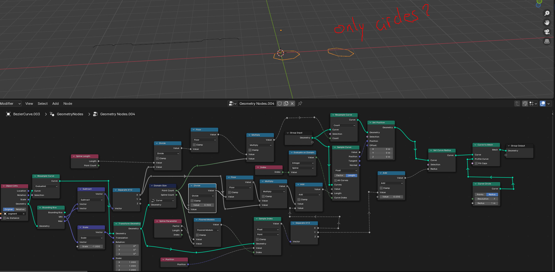
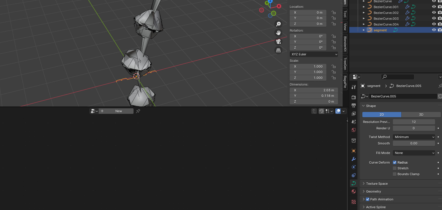
I also added the bezier i created the geo node tree in, but it shows me this error and i cant see anything on the viewport, i mean there is currently no mesh/curve. Trying to figure out where my issue is.
Just to be clear: you have two curves? One with the modifier and another one without the modifier (that modifier refers to through Object Info), right?
Well, I may be doing a mistake interjecting on your conversation here, but it looks two me there was supposed to be two curves.
You can’t refer to the same object you’re modifying from Object Info. At least you can’t get its geometry this way - you have Group Input for that.
So, it stands to reason, that Object Info in zeroskilz’ tree has to refer to some OTHER curve.
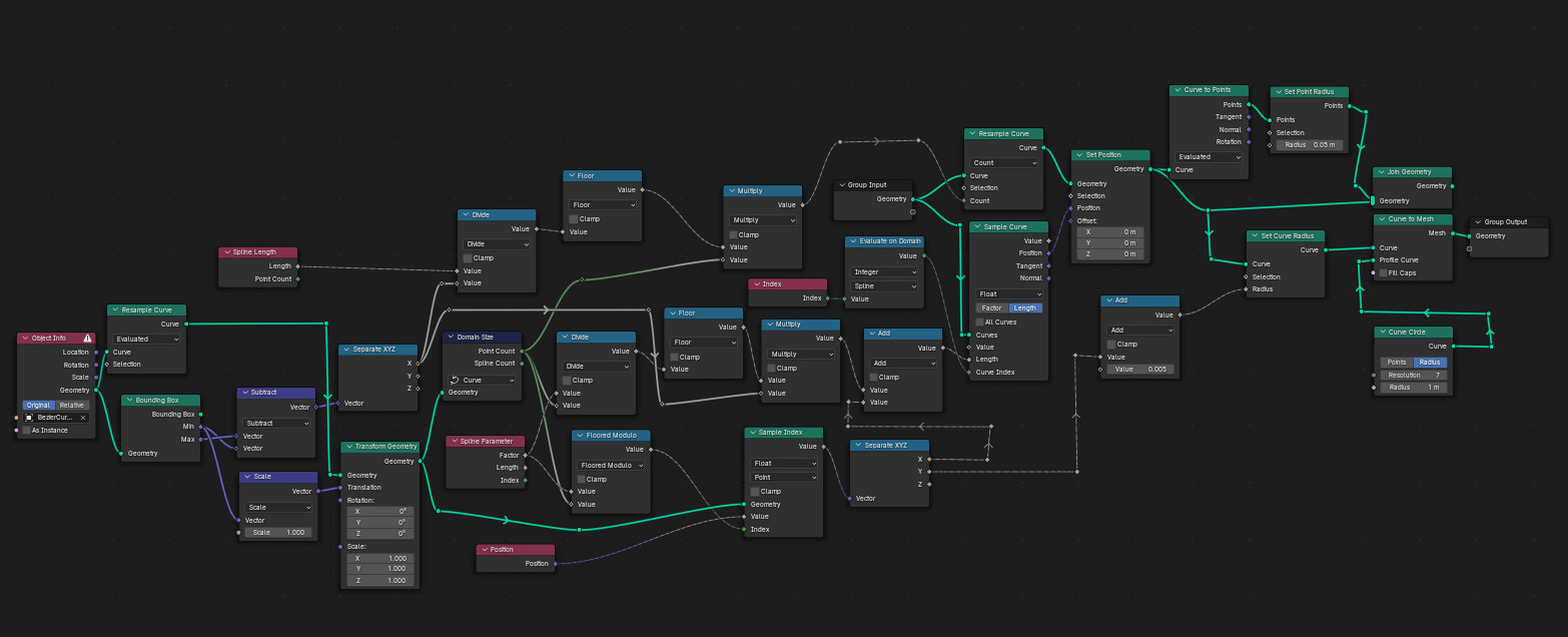
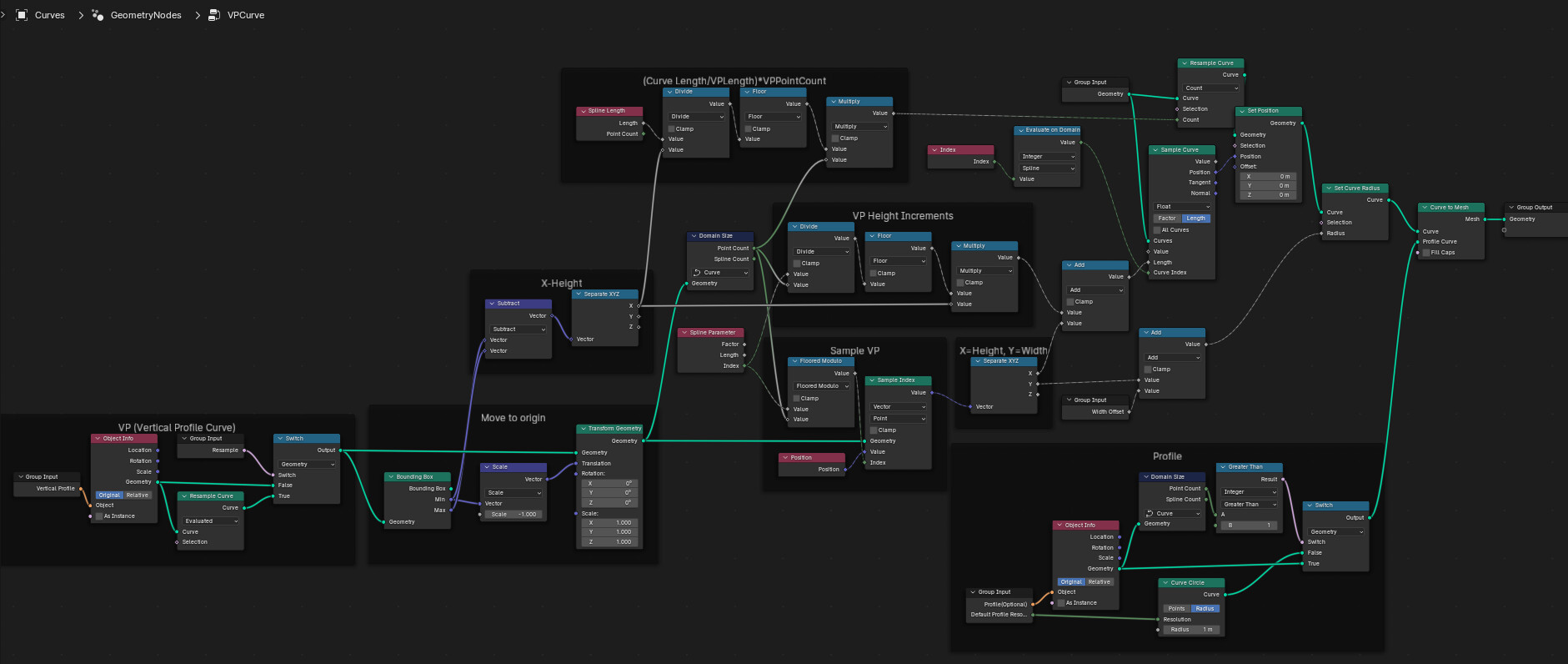
Yes. as stray pointed out, the set of curves the GN operates on are the “carrier” curves (the curves the GN is attached to i.e. the Group Input):
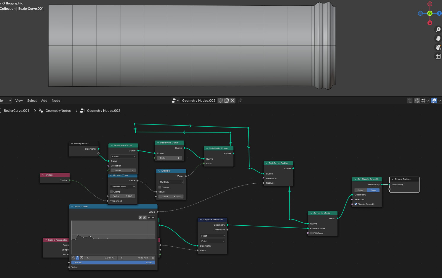
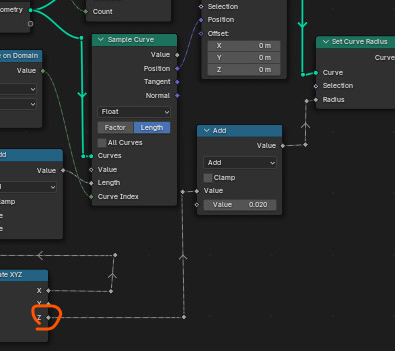
The one from the Object Info is the 2D vertical profile curve:
This is the curve that is used to sample the offset of the points (x-component) and the width (y-component).
Since the curve is placed so it starts at (0,0) an offset value is added to the curve radius (to give it width.).
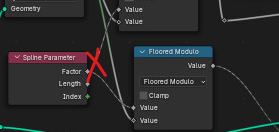
Also, don’t use the curve factor
use the Index.
This bit here
… is just for debugging… its not needed.
Also, you’re missing a -1 here:
the transform is meant to move the curve to (0,0)
What? Why???
You need to use the Spline Parameter Index or it don’t make sense! Each spline’s length has to start at 0, the Spline Parameter Index is the 0-based index for each spline whereas the Index read node will keep growing independent of splines.
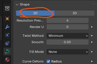
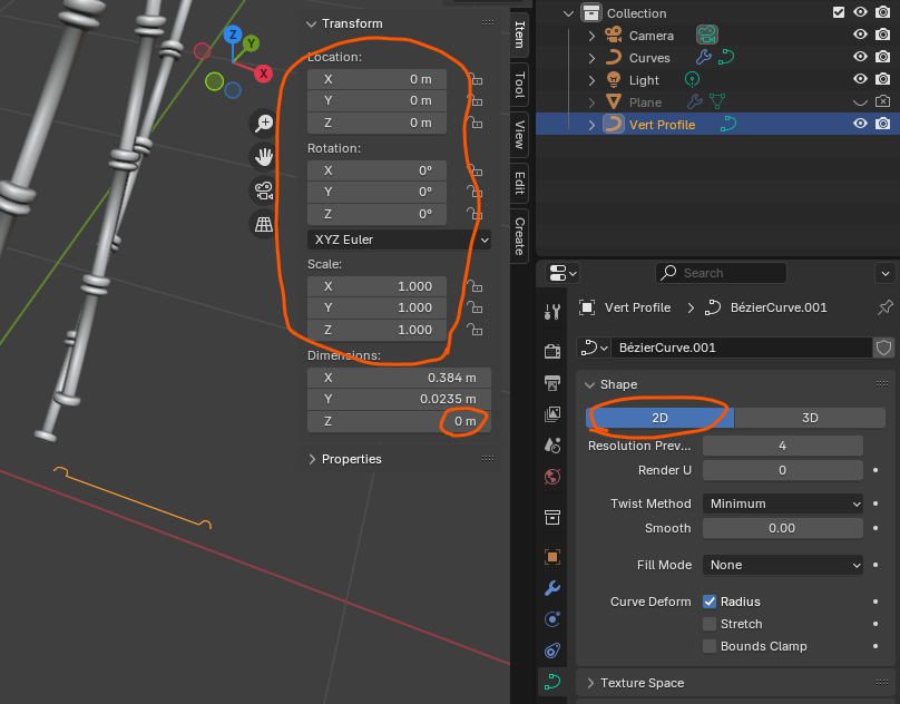
Also, your “vertical” profile “segments” needs to be way smaller than the curves it is going on or it doesn’t make sense. Make sure this curve has transforms applied. Also, for this curve, choose the 2D option to keep things sane.
And no, using float curve is a bad idea since you can’t get the number of points or their x-positions from that node.
You were not supposed to copy me (I’m really sorry that you could make out my initial screenshot. You were not supposed to.), but rather ask questions to gain understand as to what I was doing instead. It is clear you don’t understand what you’re doing. This topic is a complete failure and hasn’t taught anyone anything.
Sorry everyone.
The best way to learn things, is to copy and see the result, as the brain works best with visual associations.
In our other thread, first you showed me how to do, then i copied, and after things was done, i asked questions, i explained myself at the end what i learned. I really dont understand your feedback, to be honest. A lot of people, and i speak out of experience, will see our thread one day, and will 100%tly face the same issues as i do, and when we now close the topic, because the results are not there yet, or i didnt build the perfect second way to achieve same results, then no one will learn from it
I even had a different approach, and still working on it…
I think your feedback is very sad, so i excuse to everyone for this feedback.
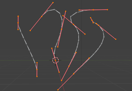
and here is my side panel, if you still willing to teach
By the way, i learned at the very end of the first thread.
I even applied my learnings to a new project, which i will post today. So again thank you for teaching. But i understand your fustration too…