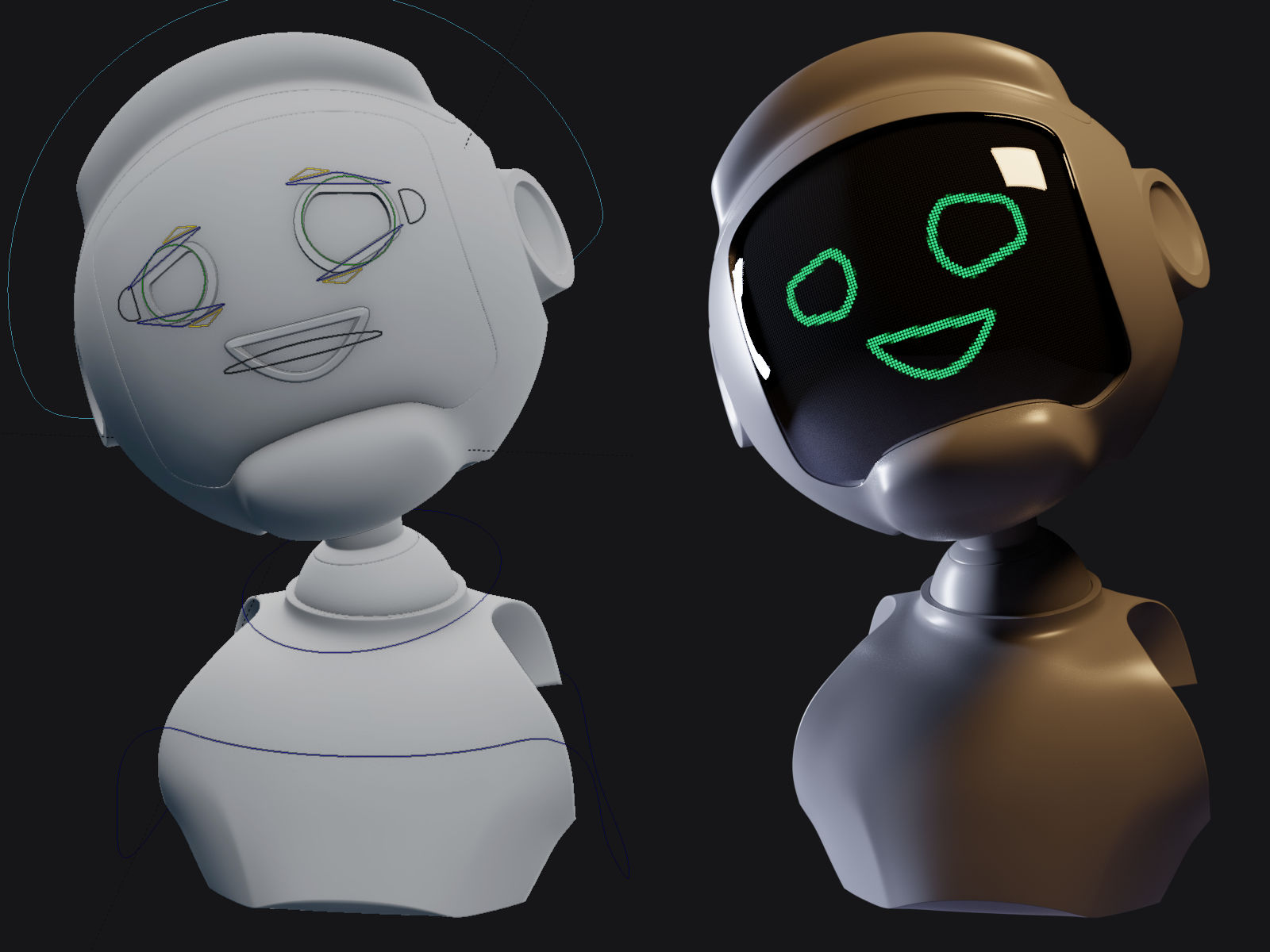
After watching Next Gen, I was inspired by the LCD-like displays of the robot faces. I had an idea about using dynamic paint to drive the material. The basic idea is to render out the dynamic paint into an image sequence. Those images are then fed into the material where it is pixelated.
And blah. blah… Just go check out the included .blend file and have a play with it.
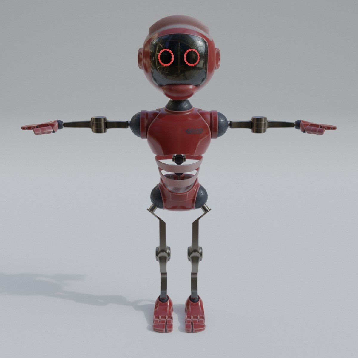
I’ve made a bunch of updates to the material to make it more intuitive. I’ve also included a part of my rigged robot so you can play around with the dynamic paint aspect of the setup.
It’s not so bad once you weed out all the extra fluff I included. I’m about to go to bed, but I’ll break down the nodes for you the next time I’m at my computer with some free time.
Until then, I’ll give you a hint if you want to keep tinkering with it. When manipulating vector space, adding/subtracting is like translating and multiplying/dividing is like scaling. With that in mind, mute the chains of math nodes then unmute in order of operation to get a sense for each step.
Ok, here’s a breakdown, ebi. Hopefully you like reading.
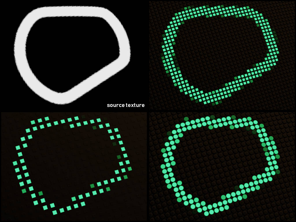
First let’s break down the Quantize node group. This is responsible for pixelating the texture it’s fed into with some vector math. To do this, we need to work on the X and Y (UV) coordinates separately.
The nodes in blue aren’t essential to the function, but let’s start there. Our goal with this node group is to pixelate an image, and allow you to to scale the pixels up and down. When scaling in UV space, the transform happens from the origin (0,0) which is at the bottom left corner. That works fine, but I wanted the pixelation to line up to the center of the image.
See in the .gif how the pixels are perfectly centered as the pixels are scaled? The blue nodes are responsible for this. When modeling, you can move the pivot to where you want to scale from. In UV space, you can’t move the pivot to the center of the texture, but you CAN move the center of the texture to the pivot.
That said, here’s what’s happening, starting with the blue node in the top left:
Get half of the pixel size.
Add that value to 0.5.
UV space is 0 - 1, so this gives us the center of the U/V vector PLUS half of one pixel (so the “pivot” is at the corner of the pixel, and not the center of it.)
Now get the vector and subtract (translate negatively) by this center value.
At this point, the center of the texture has moved to the bottom left corner. Now we can scale from the center.
In the first gray node, take the vector and divide by (scale down to) the pixel size.
The texture now tiles across the mesh. If the vector length is 1 and the pixel size is say 0.05, then 1 / 0.05 = 20 tiles (pixels) across. In other words, our vector space was scaled from 0.0 - 1.0 to 0.0 - 20.0.
It’s as simple as the quantize group when you take out the blue and red nodes. Just like before, the blue nodes have to do with changing the scale “pivot point”. The red nodes are simply there to make pixel gap and pixel squareness sliders more user friendly. That leaves you with 5 gray nodes doing all the work.
I’ll skip the blue and red this time:
Divide the vector by the pixel size.
Feed this into a modulo, which in most basic terms, repeats the texture
This group is being fed into a procedural gradient texture, which doesn’t repeat like an image texture does.
Subtract (translate) each pixel by 0.5 to re-center them. This node should have been blue.
Multiply (scale) each pixel individually by the gap size
Feed this into a power node with the exponent controlled by the squareness input.
The higher the exponent, the sharper, or more “square” a curve looks.
This node group is plugged into the gradient texture.
The gradient is plugged into a “greater than” node to make it solid black and white. This is your mix factor for the lit and unlit pixel materials.
The gradient texture can also be plugged (without the greater than node) into a bump map node to give the pixel grid some dimension.
That’s about it. Let me know if that clears things up for you.
Hey folks. I’ve made a bunch of updates to the material. I’ve also gone ahead and included part of the robot from a project I’ve been working on so you can play around with the dynamic paint rig.
A note on the mouth dynamic brush: There are some basic shape keys hidden away if you select the mesh. I’m just too lazy to properly set up drivers for them.
I’m having issues importing an image. Where there should be an “Open Image” button, there is a slightly different one called “Unpack Item”. Help a brutha out?
Hi MerlinsMaster. The .blend has an example texture packed into it if I recall, which is sort of like a .zip file. You can unpack it by going to file > external data > unpack all. You’ll end up with an extra texture on your drive, but should then be able to open your own.
Hi there! This work is truly amazing (and a lot of fun to play with)!
I’m having trouble with the animation though… I’ve opened my 3 face images, set the “image texture” node to image sequence in order to animate them using the "offset button. But when I change the offset from one number to another (say 1 to 2) the face disappears… I don’t understand why.
Some additional hints: the 3 images a correctly set as corresponding to offset 0 to 2, though to see them I have to change the image selected in the node, and set the offset at the value corresponding image.