Hi guys. I am new to Blender, learning it in conjunction with Unreal Engine, a newb there too. Anyway I am studying blender documentation, and have taken one of those quick version tutorials, and have been researching, but some things are very easy to ask. So if you are interested in helping would love to hear from you.
Question 1: Mesurements
My understanding is that the standard size in Blender is 1M. When I create a “grid”, I see that it is divided into 100 sections 10x10 (faces?) by vertices. Would this grid be 1 M or 10x10 M, I assume the latter.
Question 2: Girds on Grids
When I create a grid, it appears sitting on a much larger grid. Are these both called grids?
The first gird I made took up 4 squares on the larger grid it was sitting on. Yet it had 100 sections. That bottom grid, does this have a standard size and increment or is it totally fluid?
Question 3: More on Grids: As a standard practice, should a grid that you made be made to scale to the grid it sits on or no? Out of curiosity, can the the bottom grid or is it a scale (?) be made invisible?
Question 4: Snapping. I’ve noticed using Shift S there ae different things to snap to, but is there a toggle snapping off and on? I’ve not found that setting yet.
Question 2: Girds on Grids
When I create a grid, it appears sitting on a much larger grid. Are these both called grids?
[/quote]
A grid object is a 2D sub-divided plane. The other grid is imaginary and is there only to orient you to Blender’s workspace.
Fluids are a completely different animal.
No.
Yes.
Yes. It’s on the Overlays menu.
1 Like
Renzatic
(Professor Emeritus Billy H. Wafflesmith XIV Esq.)
3
The smallest unit on the grid defaults to 1 meter, and thus the larger grid is 10m. If you’re intending on working between Unreal and Blender, then treat each big square as 1 meter, with the smaller subdivisions being 1cm (I think that’ how it goes anyway.)
You can change it by going into your scene properties tab on the right (the icon with the cone and two little spheres), and change your unit settings. Though keep in mind that if you do end up making something that’s too small or too large, you’re never more than a quick scale away from fixing it. Almost every model I make ends up being too large by default, since I only worry about relative measurements.
When you’re working with your polygons, the proper terminology isn’t a grid, but rather your mesh. The grid is simply there for backdrop, to act as a guide if you so need it. If you have a mesh that’s equally divided into 100 sections, that’s your topology, and it can ultimately be whatever you want it to be.
Nope. Like I said, the grid is there to act as a guide. All the cuts and transforms you make on your mesh are entirely up to you.
Yup. Your overlays menu is at the top right of the viewport. It’s the two overlapping circles icon.
Hey there Ren, good to see you here.
I only called it a grid, because that is what blender labeled it. At first I was calling them meshes.
As you know I’m trying to duplicate a project that was started in Maya, and what the author creates is 12x12. I have been unable to determine how big this grid is. If I assume it might be 1 meter per segment but that would be 12x12M which is kind of wide for a dirt road through the woods, but maybe not?
So I am mulling this over in that I might want my road to be 15’ (approx 3 meters) instead of 12M, approx 36’. Now as you said why worry, just make it and change it if necessary. But those were things running around in my head. The author may have scaled it down and I did not noticed, but as you said, just scale it as needed.
Thanks per usual.
Question 5: Removing and replacing vertices: This may sound ignorant (which it is ;)), but when I create a mesh, it has 100 faces on it 10x10. I want my mesh to have 12 equal sized segments that that cross this square.
So what would the best way to remove all the faces and replace with 12 that cross the width of the square, or just extrude two more sections outward to go from 10 to 12 segments? I’m thinking what is the least amount of work? And wondering if it makes any difference if this mesh is is now 10x10 or 12 x12 because I extruded it?
Renzatic
(Professor Emeritus Billy H. Wafflesmith XIV Esq.)
8
Sup!
I watched that video, and I think he’s just pretty arbitrary about the size. He’s only worrying about how it looks. Though if you do want to use the grid for size, then treat each grid square as 1 meter, and when you’re done with your object, and are about to send it to Unreal, scale it up by 10 on X, Y, and Z.
And, of course, you can always rescale it inside of Unreal as well.
Question 5: Well, you can select all your edge loops, and dissolve them by hitting X, and choosing Dissolve Edges, which will remove the selected edges and vertices on the mesh, while keeping the shape generally intact.
Though really, when you drop a plane primitive into your scene, it should just be one face. How exactly are you creating your meshes?
Howdy! Somewhere I picked up on adding grids, instead of plains, saw that when I watched your example and you were using a plain. So using the measuring tool it appears that a plain is the same size as a starting grid, 4 squares 4x4m total. Even though I know I can scale it, can you have a measuring tool functioning as you scale an item, or does it display over on the right side in details, somewhere?
It might be better at this point if I make it the desired size and since he is working with 12 sections to model this road through the woods, the hump between the tire tracks is 4 sections (4m) wide which is too much for a standard vehicle which I’d guesstimate more like 4-5’ between the tires, so say 2m. Based on that hump and tire tracks 2m apart, and 12 sections, I’d say that little road os more like 6m across about 20’.
So I’ll probably work with a grid of 3x3 plains, and then add in the extra divisions to make it 12 sections across and go from there. The whole time I know there is a way to quickly add these and I think your example has that. Will check again.
In the example I’m copying he is working with a square with 12 sections all the way aross, he lifts the center pieces and it causes the connected pieces to angle up to. The question is does it matter if this is a plain or a grid that is being manipulated?
Btw, I don’t know what your preferred measurement system is but I’m stuck solidly in English, but can adapt readily to Metric.
Update: I got the plain made with the 12 diviisions and got it bent the way I need to. Scaled it to the size I wanted 6x6, and then use the face select and edge select- Move to lift the sections in the way they needed to be lifted. I’ll see if I can get a screen posted.
The hotkey for SNAP is SHIFT+TAB. (Note that you must have your cursor over the 3d window for this to work --plus, it must be the 3d window in the greater, active window-- IOW if you’ve opened a secondary Blender window, you must click in the one you’re working in.)
I don’t know of any hotkeys for the various options within Snapping.
Note that for every possible option, there are more/different flags to set in the SNAP panel. If you are learning it’s a very good idea to go thru and at least think about all the possible options.
PLUS, you can have more than one option engaged at a time: iow, you can SNAP to Vertices and Faces, any combination, or all.
The “Increment” option has a flag for “Absolute Grid Snap”, which defaults to OFF. I think that’s a bad default. You may be able to save a STARTUP.BLEND with that ON so you don’t have to mess with it.
SHIFT+S just gives you some immediate, convenient snapping options – “Cursor to Selected” is a good one to memorize.
So Shift Tab is toggle on and off. I was looking for an off selection when used Shift S, but did not see that. But I do see the magnet lights up and dims, signaling toggle. Thanks!
Renzatic
(Professor Emeritus Billy H. Wafflesmith XIV Esq.)
12
Remember, I’m not working from a tight grid, making sure everything is neat and even. You don’t have to be quite so exacting when you’re modelling. Think of it less like a CAD program, and more like you’re sculpting with chicken wire. If you need more detail in a certain area, you run another wire or two through that area.
I’ve got the first part of the mesh made. But having some trouble getting the Proportional Editing to kick in. In the following image taken with my iPhone (next post), the little sections such has highlighted need to be dragged a little up or down, left or right and drag the accompanying vertices with them to make it look irregular.
This is my grid. It looks pretty good, although the angle you are viewing it at does not show off the curves in it.
But I need to make it look irregular. The way it’s done it is by grabbing faces with a proportion editing tool I think and dragging these off center which pulls the adjacent line segments with it. See example in next post.
This shows it being done in a tutorial, but I don’t know what controls are being used. Yes, it’s a great tutorial , but more like a tech demo. You can see the distortions in the grid that have been introduced.
In Blender, in Edit mode, Face Select, I pick a face, Hit O and Alt O, but nothing happens. Any ideas?
Thanks!
UPdate: OK I see O turns on proportional editing, but you have to use something else to make changes, would that be move, scale, or extrude? When I move a face sideways, it ends up showing a double line like the original line and the new line. Is that just what it’s showing?
Renzatic
(Professor Emeritus Billy H. Wafflesmith XIV Esq.)
15
Yeah, proportional editing isn’t an action, rather a mode. You can scroll your mousewheel to change the area of influence.
Starting out, it might be easier for you to use the manipulators, rather than doing things the classic Blender way. Look for the 4 arrows pointing in the cardinal directions in the toolbar on the left hand side of the screen. That’s your move command. When it’s active, you’ll get a manipulator that lets you drag on some little arrows to move your elements around.
Welcome to BA!
Ok…first off… Things can be very confusing when first starting off with Scale – Units --Dimensions and Grids in Blender…
Think of it this way…Objects are considered made up of Blender Units, and the Scale of that unit should always be 1x1x1… that has nothing to do with the actual dimensions of an object…when you add a plane, for instance, it is added at 2x2x2. You determine what a Blender Unit is…either Meters, Millimeter, Centimeter, etc…that is located under the N-Panel ( Right Side ) under the Scene Properties.
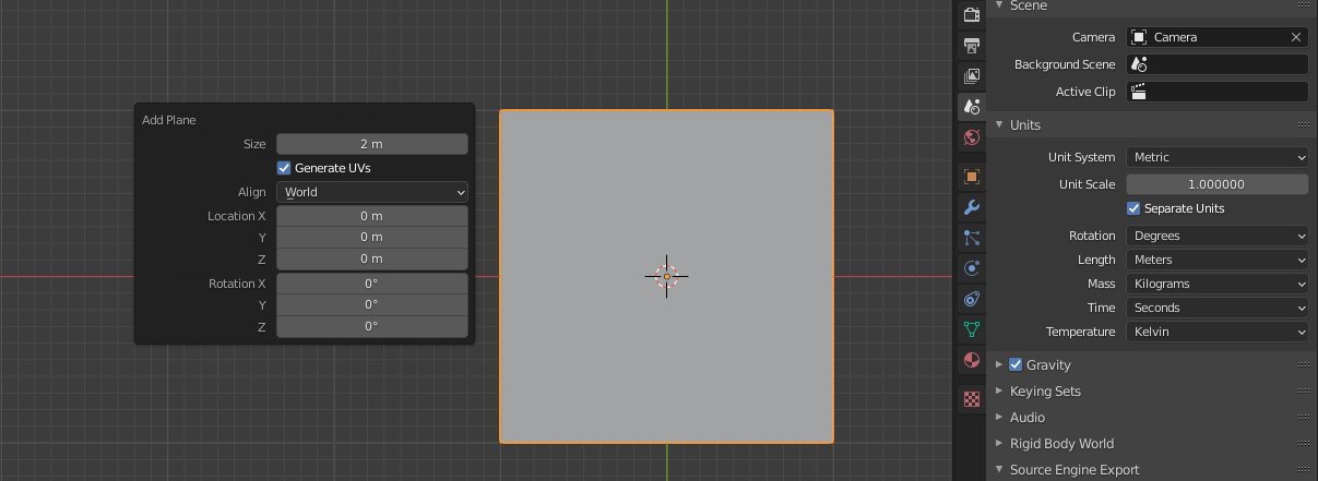
There you set the Units you are going to be working with if working on the world scale, which is a good practice to use. Blender does default to Meters…so when you add a default plane it is added as 2x2x0 meters. If you notice when you add a plane there is a pop-up in the lower-left corner, if you open that you can set the size to whatever overall size you want.
If you select your unit scale to Centimeters, then when you add a plane, it will have a scale of 1x1x1 and the dimensions of 2cm x 2cm x 0cm…it is a lot like using an architects scale in drafting where you are saying this Unit = This Measurement or 1/4" =1’-0", for example. Same for the Grid, that plane imports at 2x2x0 and fits on the major divisions of the grid so that would be 2x2x0 and you want the dimensions to be in Kilometers so the Dimensions of the plane are 2k x2k x0k
![Screenshot 2021-10-18 072718|690x276]
Plane imported in Meters and scale changed to Feet…
(upload://1XfeegAxnQOpggpd1cazbTZmHMq.jpeg)
Now you notice that the dimensions have been converted and are now 6’ 6.7", and it no longer fits the workspace grid as it did in meters…as it is now changed to fit the Units of Measurement…so you can see there are now 6 major subdivisions and each is divided in 12x12 or inches…
Hope this helps and doesn’t just add more confusion…
How do you quote who your replying to in this forum?
I played with this a bit last night but ended up with some pronounced bumps that don’t look right because this section ends up being duplicated 2 times for a total of 3 sections snapped end to end and the bump pattern makes it easily identified as duplicates. It needs to be so smooth that that kind of pattern will not be noticed. So I will play some more.
I see there is a smooth tool. With this kind of a grid could smooth be used to lessen the culprit bumps? I briefly tried applying it to 3 sections snapped together but did not get it to smooth the surface like I wanted it to. Btw thanks for the video example. That helped!
Thank you! I’ve been looking on the right side of the Blender screen in a Details like panel. Is this the screen or are you pulling up a different screen?
Renzatic
(Professor Emeritus Billy H. Wafflesmith XIV Esq.)
19
I bet no one ever told you about smooth shading. When you’re in Object Mode, rightclick on your model, and select Shade Smooth. You’ll immediately see your model go mushy, which, for your road tile, is what you want.
Yes, it is. It is the default panel in Blender Factory load…on the top is the Outliner, and the bottom is the properties of the working space as well as anything you may add…as soon as you add something the bottom will open up a bunch of other tabs to work with that object…like Materials and so-forth…
 So if you are interested in helping would love to hear from you.

 So using the measuring tool it appears that a plain is the same size as a starting grid, 4 squares 4x4m total. Even though I know I can scale it, can you have a measuring tool functioning as you scale an item, or does it display over on the right side in details, somewhere?