Declaring separate pivot point
Possible using a dedicated special mode so workflows remains as simple as possible
More tools
While possible, it is not a viable option.
There are basically 2 ways
Write new operators around snap, but we must implement our own special replacement for native blender’s operators - they often are “modals” meaning interaction is not possible from python side when running - or hackish / not always reliable.
Enhance native snap and use it in existing / new operators, the Germano’s way. The only one to actually get required level of access to snap while native operators are running and in the end the larger possible benefits.
Support for empties
You may snap to empty “origin”, there is no other available geometry in empty to snap to.
Constraint
Will take a look at allowing such things.
Declaring seperate pivot point
I’m sorry, I don’t understand what you mean.
Do you mean it’s available without the add-on or using another add-on?
Or do you mean it’s available within this add-on? If so, how do you this / activate this special mode?
Support for empties
Ah, okay. I must’ve thought that the empty’s origin would be accessed with the vertex snap mode.
Constraint
Great
Moving by distance apart from direction
What about this one?
I do a lot of modelling from images and need to scale to a specific dimension (ie architects plans). If I drag in an image (ie a plan) and try and use Scale 2D with a dimension (ie 17.4m) I get weird results. I suspect it’s because the image comes in as an empty with an associated image file and CAD transform looks as if it works with meshes. Otherwise great addon and hope you continue working on it. I bought “Snap Utilities” which seemed to stop development soon after.
Rescale expect a base size as reference, so it rescale based on that size. Without any reference, base scale is 1.0 so entering 17.4m simply multiply scale by 17.4
It seems that the add-on snapping features are limited when trying to use it in local view. It will detect globally. I’m wondering if this is a known issue.
Can’t reproduce such behavior on 2.83.13 ver 0.08
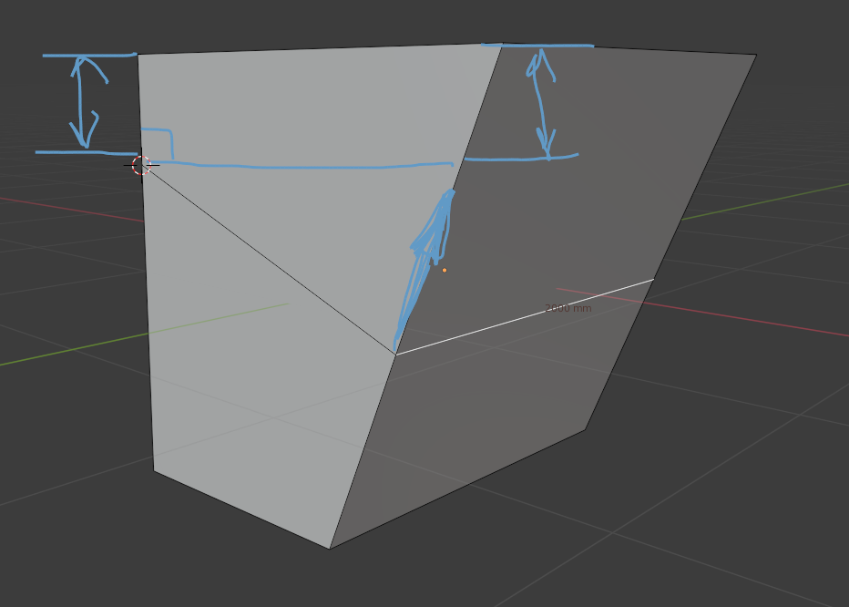
It tooks edge as length, not constraint.
What are exact steps to reach such a result, as displayed in dashed lines?
There are 2 use cases for perpendicular, perpendicular from and to.
Rotation use case is perpendicular to something. The same goes for curve editing where you have a point far from an edge and want to move another one so it lie on edge perpendicular from first one.
In this case there must be a perpendicular “from” edge at vertex location and we should compute intersection between perpendicular and constraint axis. This behavior is not implemented, but looks like this use case may be relevant and deserve a closer look.
I’ve just purchased and am tinkering. The first thing I notice that’s driving me crazy is the way the grid changes/overlays when grid snapping is enabled. Is there any way to not do this and just keep the grid I already have established?
My main use for this is in the creation/design of modular game environment kits. For example, a kit will be designed on a strict grid spacing unit: 500cm, for example. So if I have my grid set to this I don’t want to see any other grid lines apart from my 500cm divisions. When I go into CADT and enable grid I’m getting an overlayed grid of 10cm divisions that don’t even match my viewport main division lines?
When I enter/exit CADT, the overlayed grid is actually positioned differently(it jumps and divisions don’t match with my established grid)
This overlayed grid is also very jarring and overpowering as it sits on top of all objects in the viewport. Is there a way to occlude it, like the native viewport grid?
Hope this makes sense. If not I’ll post a gif. Cheers. Seems like a very useful toolkit.