Creating a new topic, as mod told me that I was going off topic with the previous one
Hi!
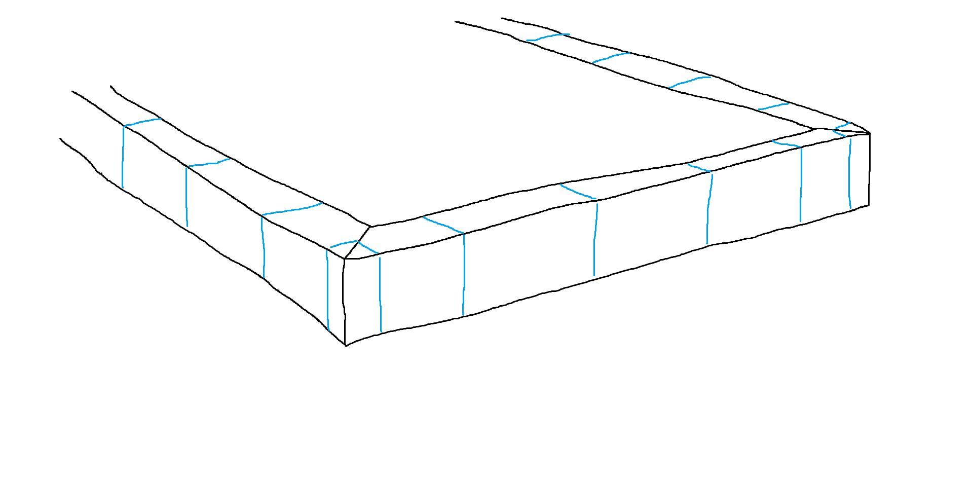
Here’s a childish drawing what I’m trying to recreate. The blue represents UV map. I have a feeling it’s pretty easy to do. But only for people that know what they’re doing
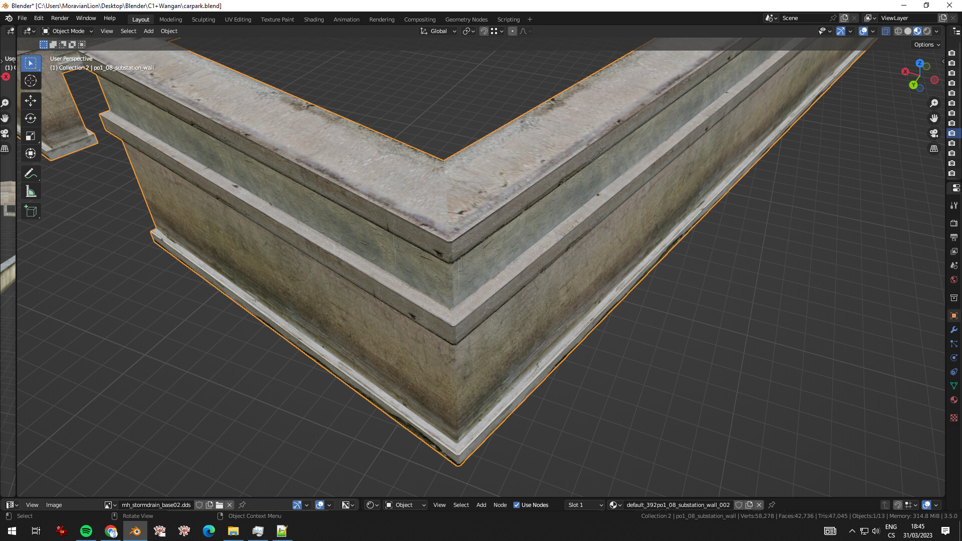
Edit.: Here’s an example how it should look when ready. Naturally, if done with curves (preferably), the UV and overall shape should respect every individual angle/corner.
Would you or anyone else know how to make this happen?
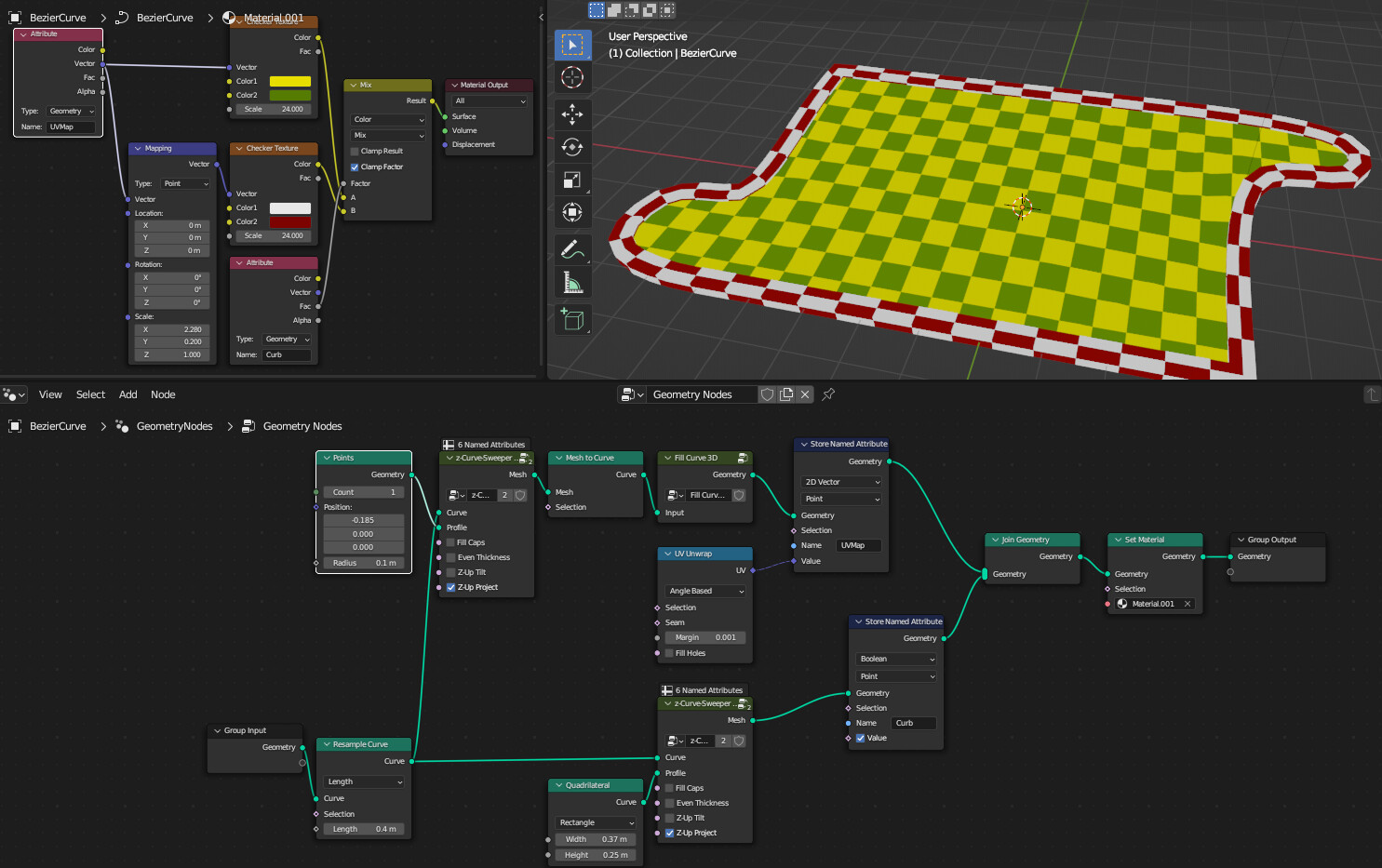
Bonus question - how to simultaneously create a filler mesh inside the curve/perimeter? Let’s think of a grass island with a curb around it, on a parking lot.
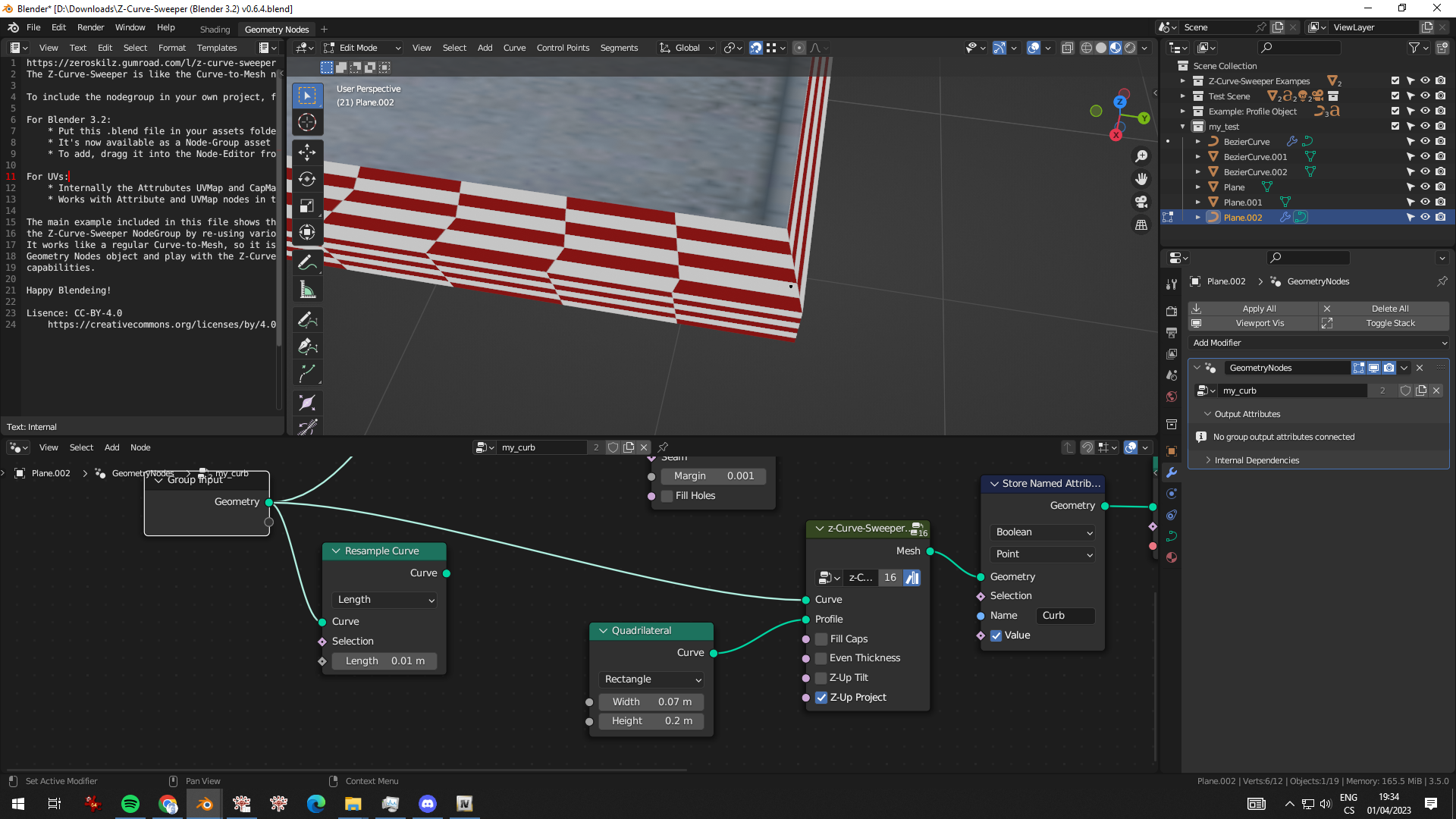
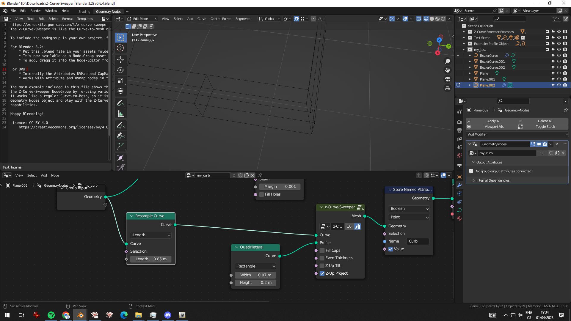
I tried the same with custom profile, out of curiosity. That didn’t help.
Any idea how to make this work?
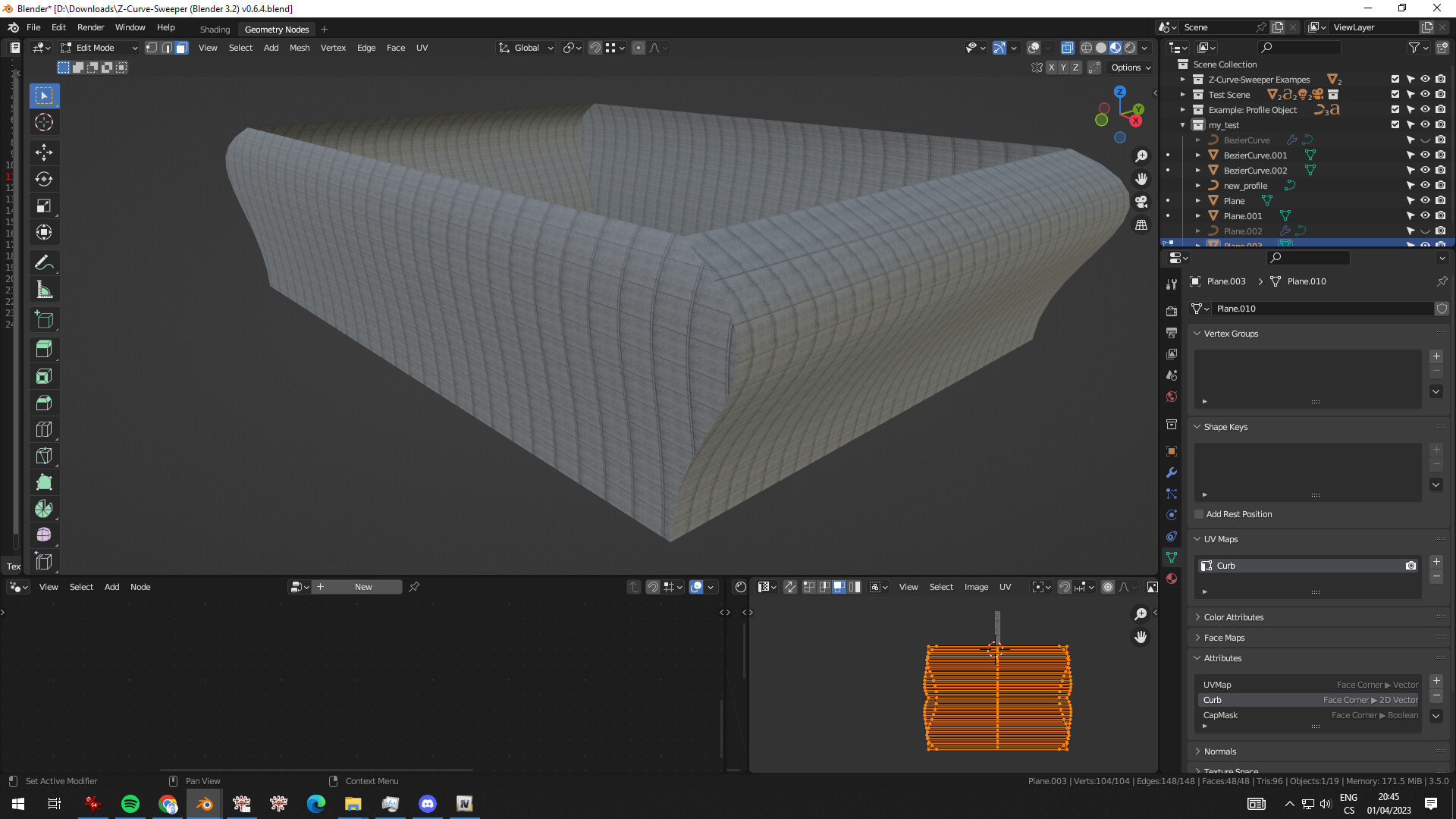
Bonus: I also didn’t notice any possibility of changing UVs of the profile curve. The middle part moves before converting to mesh, but I couldn’t figure out UVs of the mesh around edges. Apart from doing it in Shader editor, which is something I want to avoid, as I want to port the mesh into the game and need to have UVs inside UV map after conversion from Geonode modifiers.
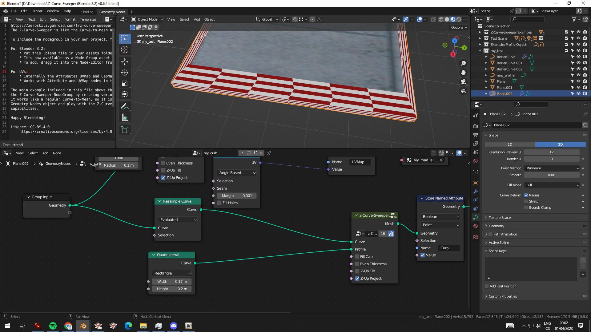
I’m hoping for something like below. Without the need to unwrapping it manually, that is.
Looks like you need to apply the scale on your curve.
Otherwise - you have to find the sweet-spot on the Length Resample that retains sharp corners for consistent curve UVs. The solution to using Evaluated Resampling is a bit more involved: calculate and capture the curve lengths and divide the UV mapping’s U value by that in the Shader Editor.
Does UV value refers to actual UV map already available in converted mesh? Or an attribute projected by geometry node set up I shown earlier? Since I need to be able to convert baked UV map together with the model for the game engine.
I’m also a bit confused about that bevel part. Could you explain more or even provide an example?
Luckily for me, I don’t care about insides as much.
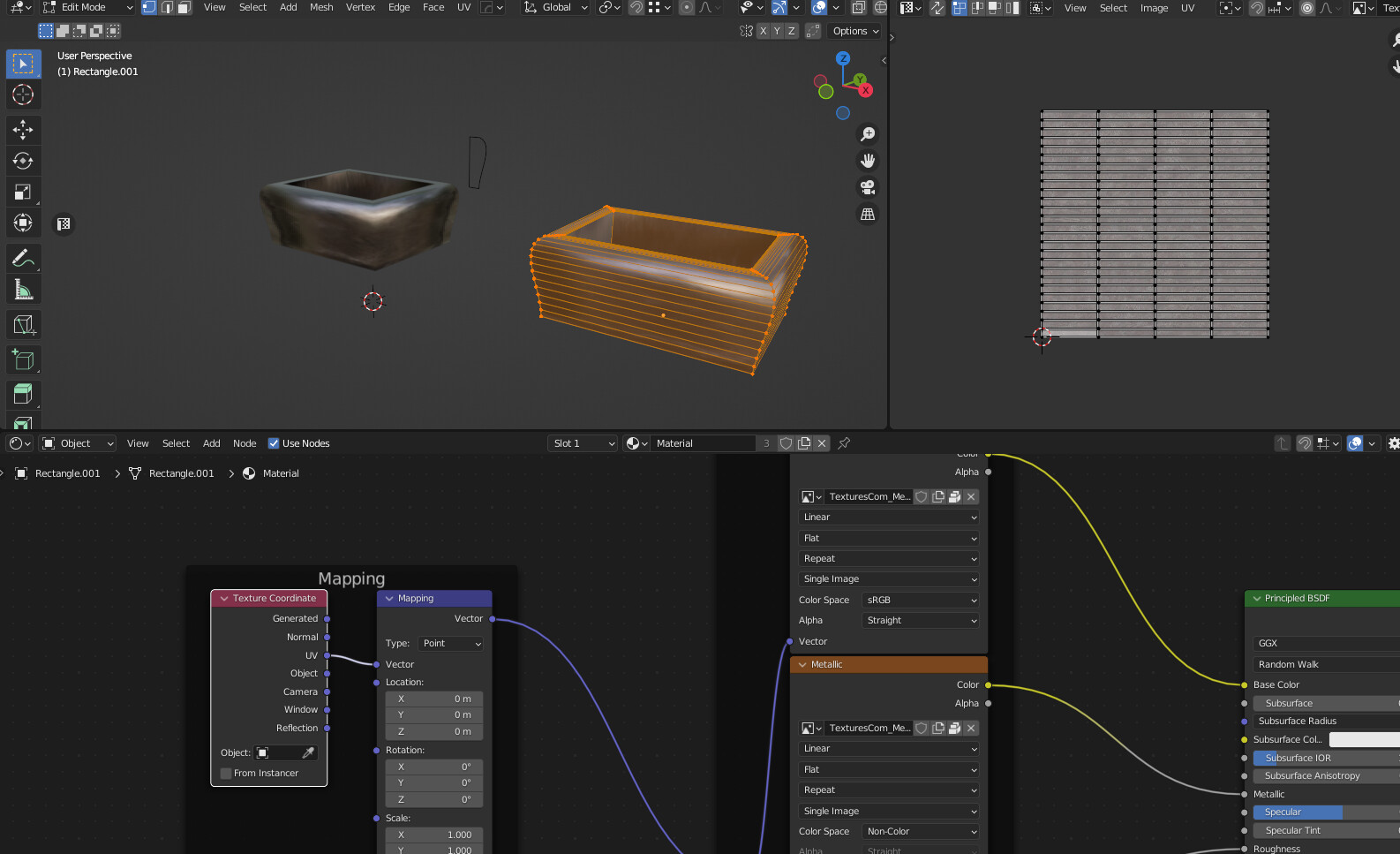
Here is a duplicate of the Curve Object converted to Mesh…you can see in edit mode that a UV transfer with it ( or is created from the original or because I set it as UV; rectangular curve form (I am not sure of HOW it works that way…)
Here is a file that I stripped the textures from ( too big) but just using any PBR texture should work just fine… you can see the curve set up on the right side… Curve.blend (2.6 MB)
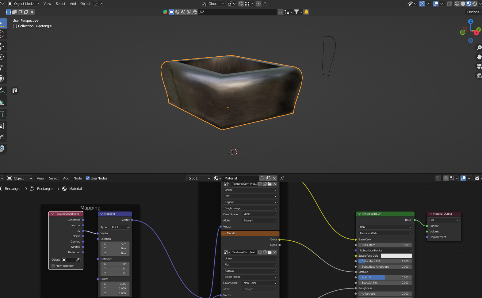
I thought you wanted the curved-sided planter. As in the bottom picture?
So what is the flat-sided planter?
It is made by creating a curved form as you see hovering outside the 1st planter…and I forgot that you would probably have to use the curve tilt to spin the texture to the outside (a major point that I forgot to mention, Sorry!)
It’s not easy for me to explain it, that’s why I posted a few pictures trying to convey the idea here.
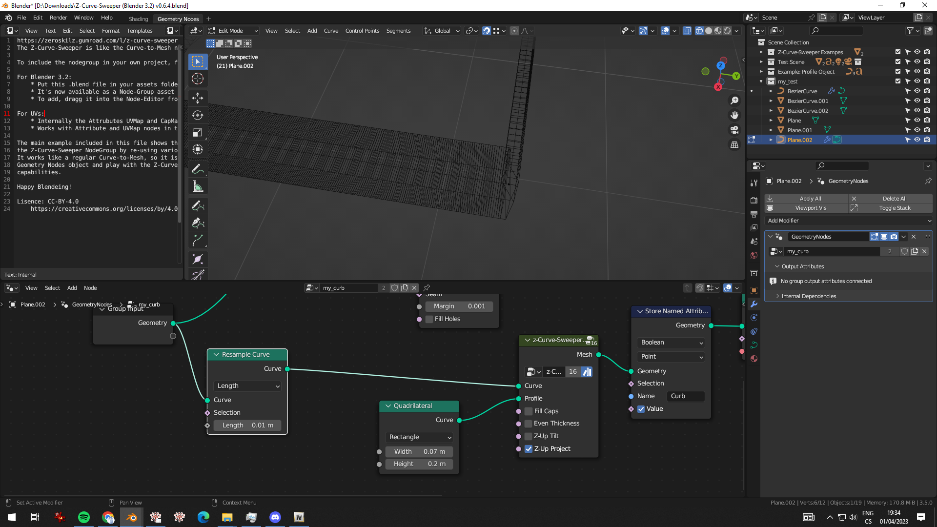
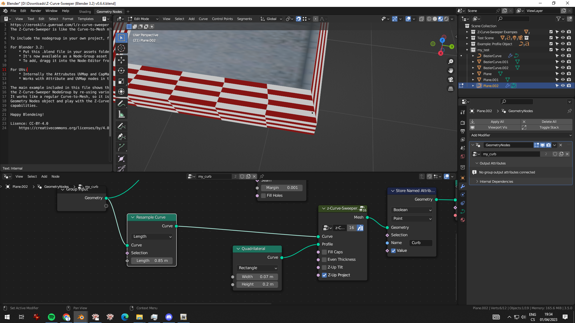
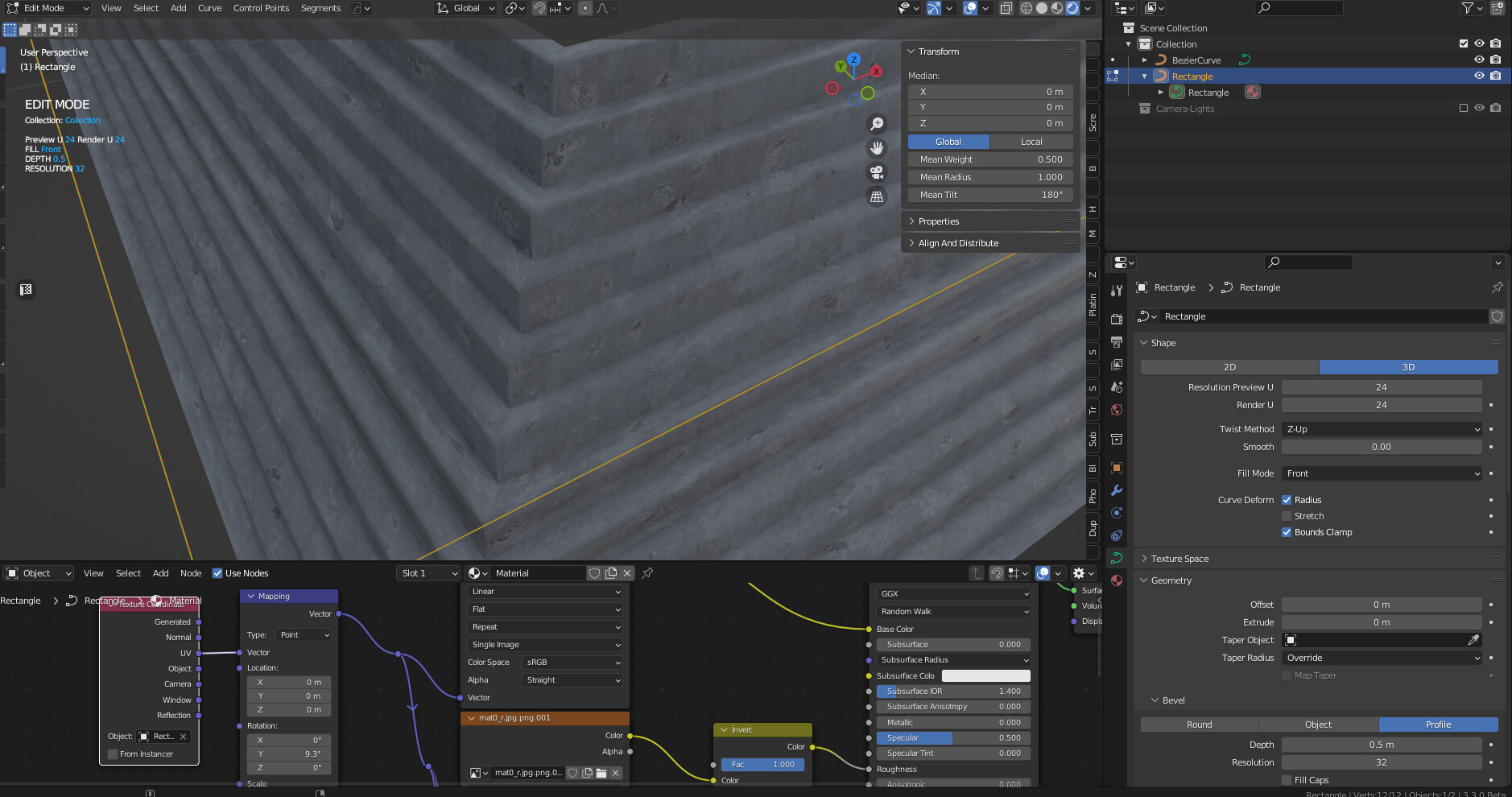
I’m trying to make sharp angles of the planters, using curves for a custom profile and the problem I’m stuck with is the fact that overall shape is great, but UVs on the final objects are stretched, not straight up.
If you use a Brick pattern it will FAIL… as well as any repeating pattern…
I notice you have Z-Sweeper …I haven’t played with it but I think that topic would be the place to ask if there is a workaround…
My issue is that I need all UV transformations to be done exclusive via geometry nodes instead. So, after conversion to mesh later, I could have already unwrapped UVs, ready for game engine.
So far, Z-Sweeper doesn’t seem to be the solution here either.
I’ve been looking for the same solution for a while now. All the node setups and tutorials I’ve found untill now don’t take in account that the UVs created with GN are stretched over the faces.
The setups use the length/factor/index of the profile curve and the path curve and are stored as the U and V vectors for the Face Corners. This creates rectangular UV islands wich are stretched to match the corners of the faces of the mesh. (Forgive me if I don’t use the right terminology)
What we are looking for is that the shape of the UV islands match with the shape of the faces.
Like when the UV Unwrap node is used. When an edge in line with the curve path and the edges perpendicular to the curve path is selected as seam, the mesh unfolds properly into a UV map, and we get UV islands matching the shape of the mesh’s faces. And that is what the topic starter I think and myself are looking for.
The difficulty with UV unwrap node is that it packs automatically the UV islands and makes the layout of the UV Map uncontrollable. When the curve profile or curve path are changed, the size of the faces and therefore the UV island changes and that can change the positioning and direction of the UV islands. I want especiially the direction of the UV islands be static.
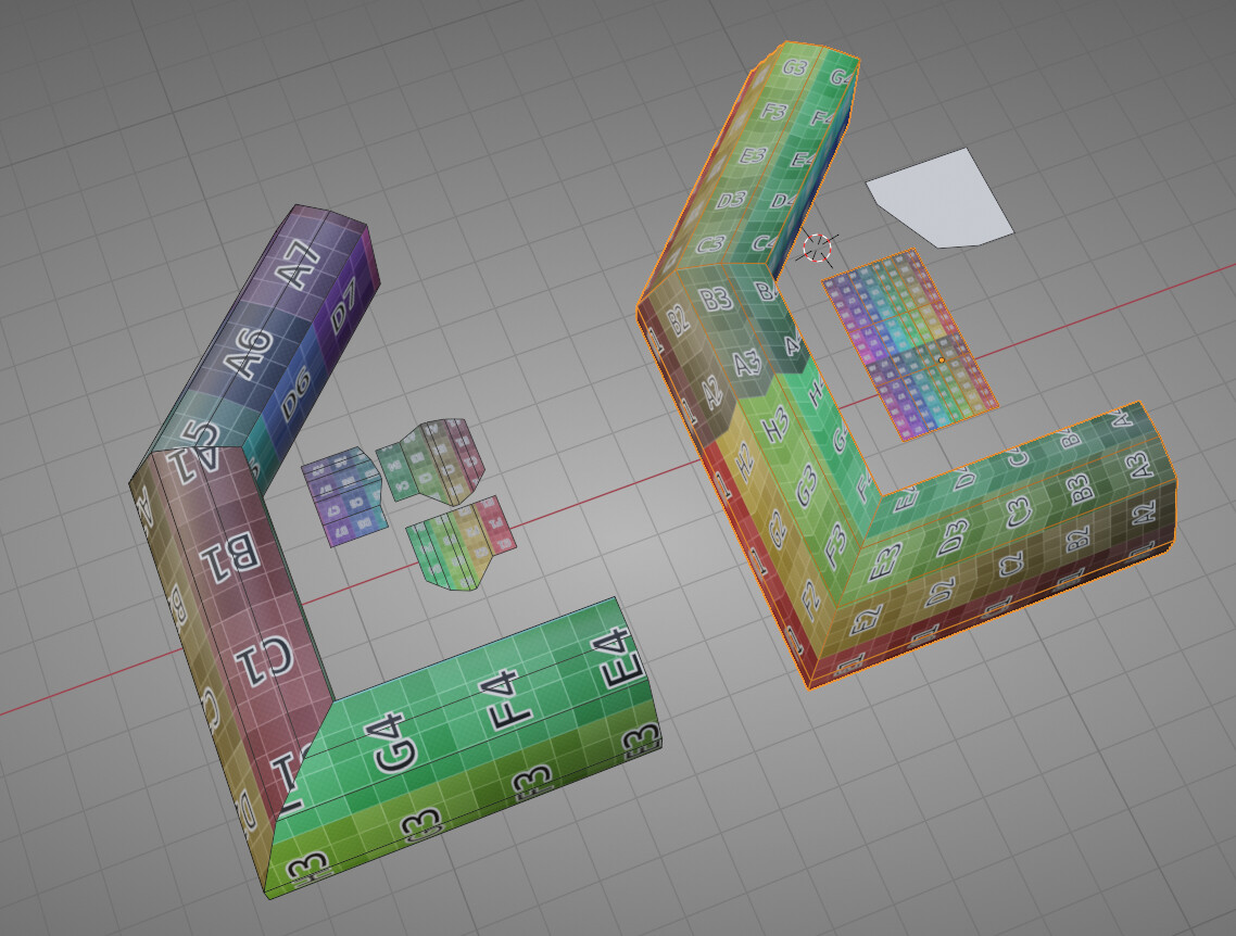
Here is the difference between the 2 workflows:
Left is with UV unwrap node and edges selected as seam
Right is manually unwrap with UV’s based on factor/length of the profile and path curves.
To get this done with manually unwrapping in GN with the current node setups I think the Face Corners should be related to the angle between the path curve segments, so the distance between the Face Corners in line with the curve path a factor of the angle,
Also the angle of the profile curve segments towards the X-axis determines the distance of the Face Corners. When the angle is 90 degrees, so perpendicular to the X-axis, there is no influence of the angle between the path curve segments. When the angle of the of the profile curve segment is 0 degrees, so parallel to the X-axis, there is 100% influence of the angle between the path curve segments. You can see this in the “UV print” of the UV unwrap node method.