Creating procedural tools for city environment design workflow - experiments

Hello,

Recently I’ve been learning geometry nodes with the goal to create some tools for myself that would aid me in my work (environment design and concept art mostly). So I decided to put into practice what I learned so far and share the journey in hopes of learning something new and maybe helping other people by sharing the process with some insights that I have. So, I will describe the main idea and plan below.

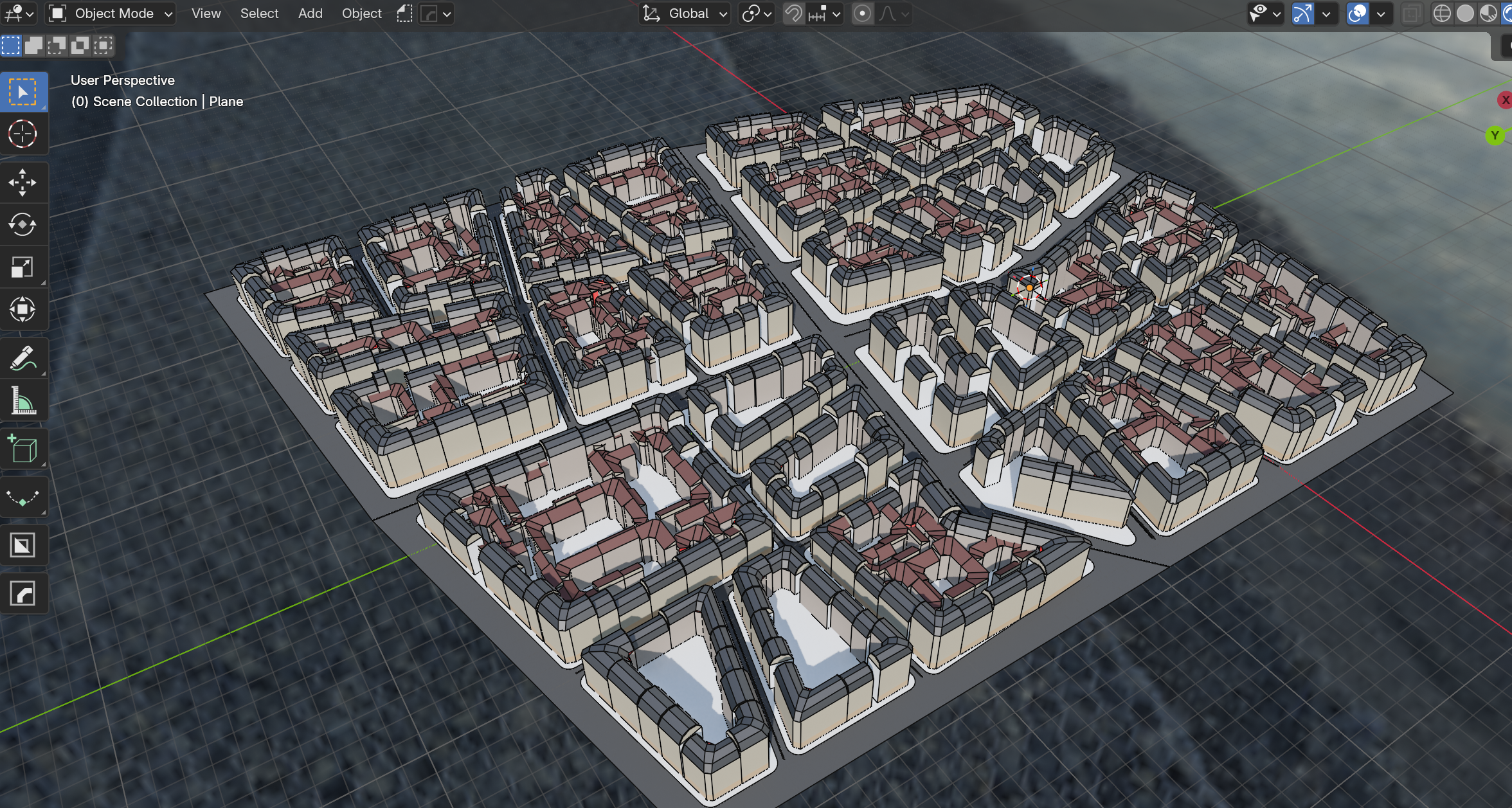
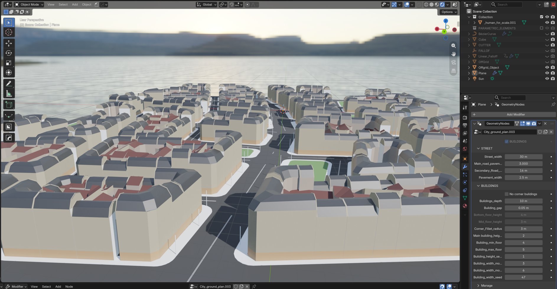
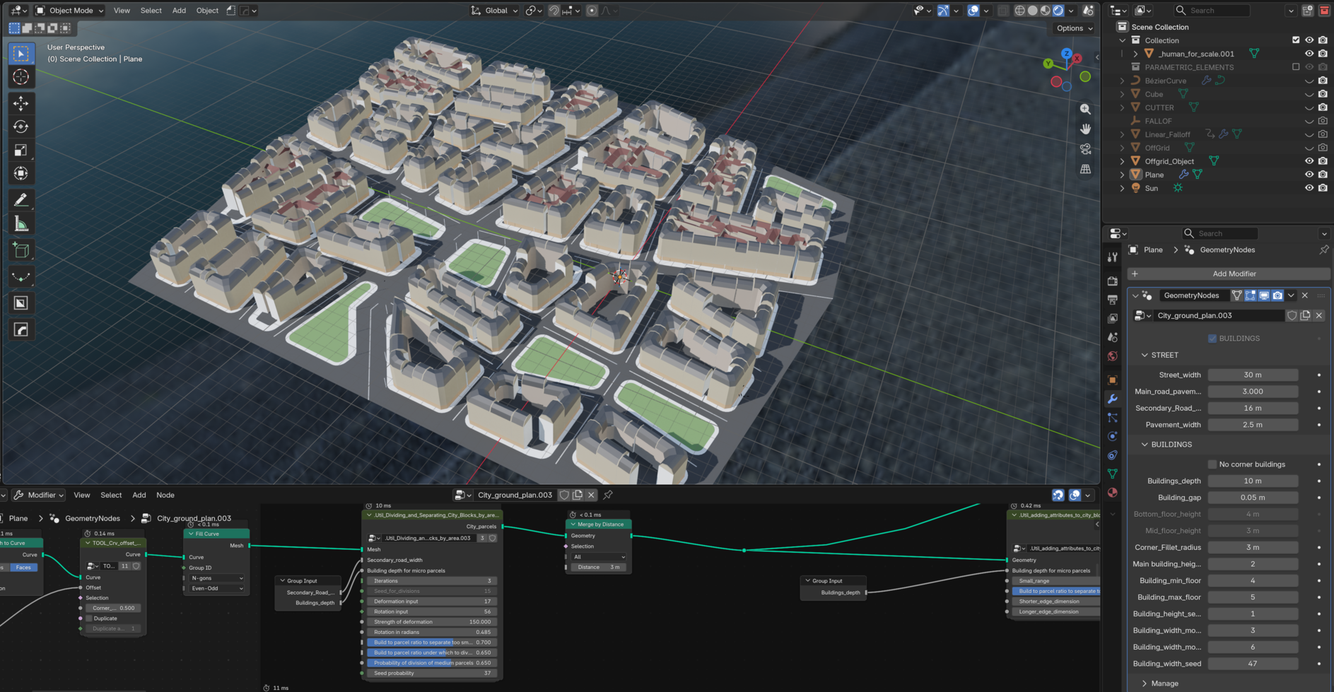
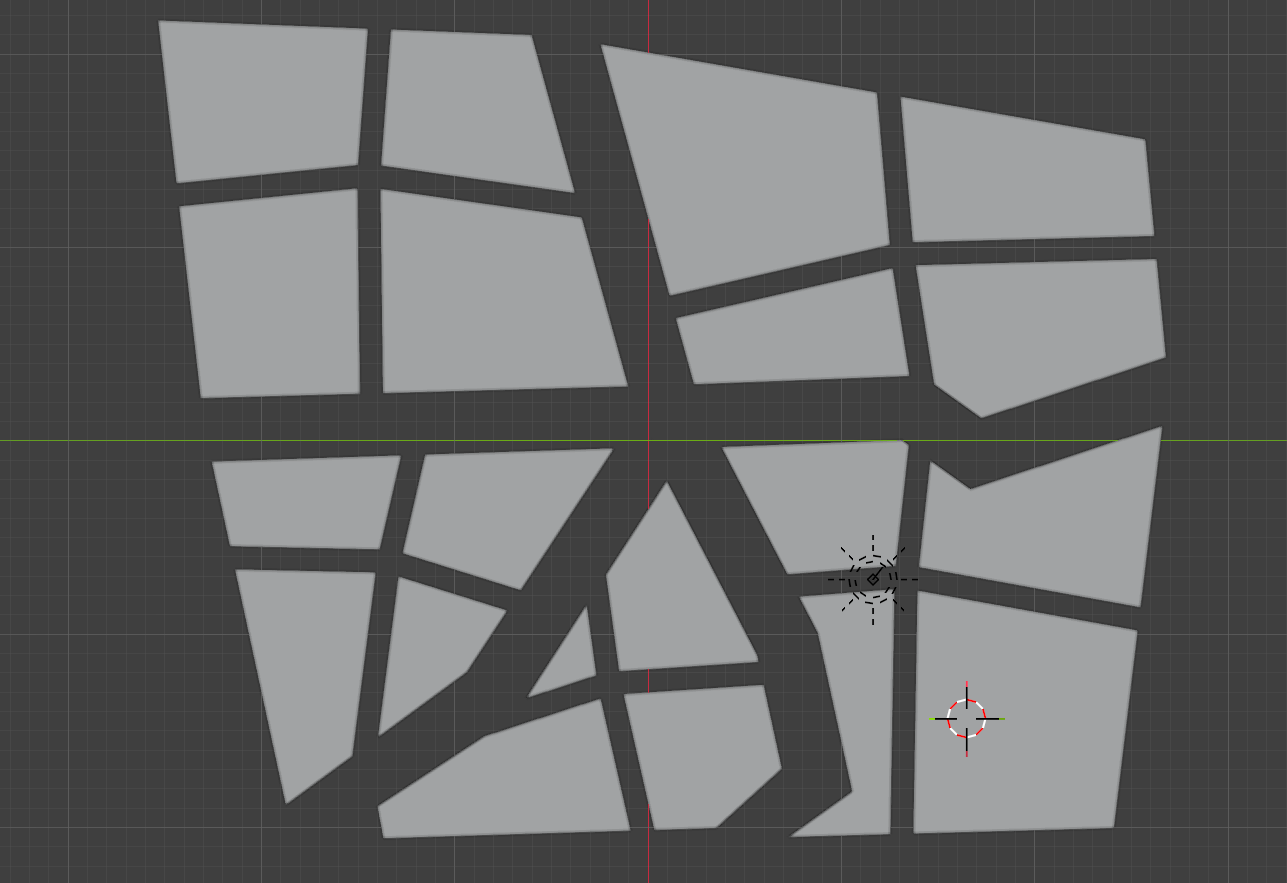
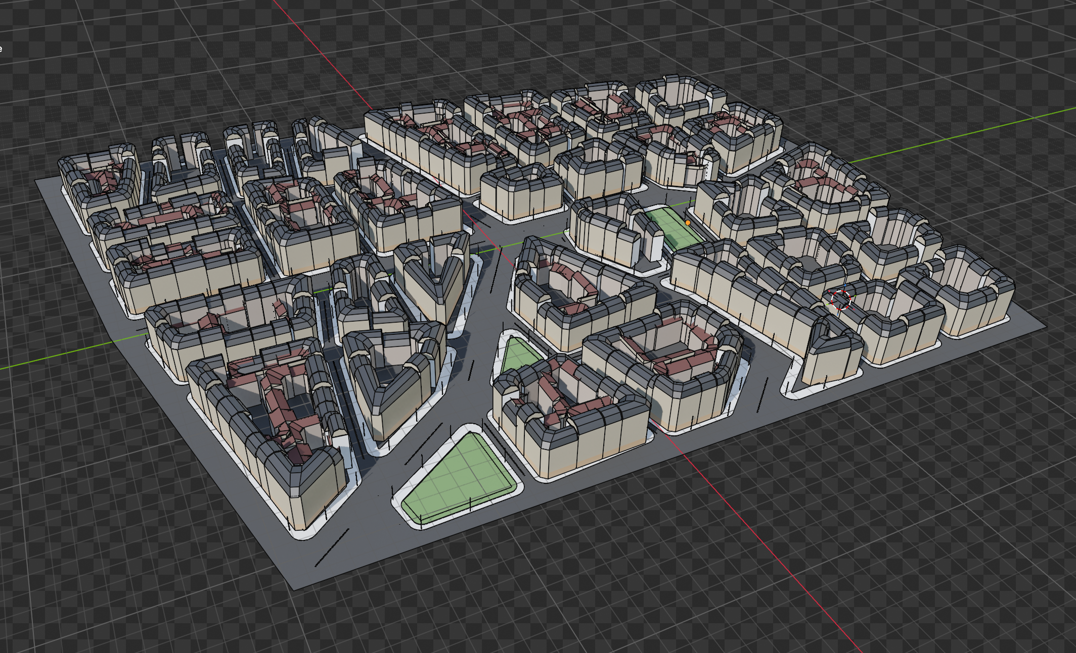
Here are my experiments with the city generator built from scratch in geometry nodes.

Main goals and modules:

  1. Create a general proof of concept system:
    a) Create main layout from the provided base plane mesh:
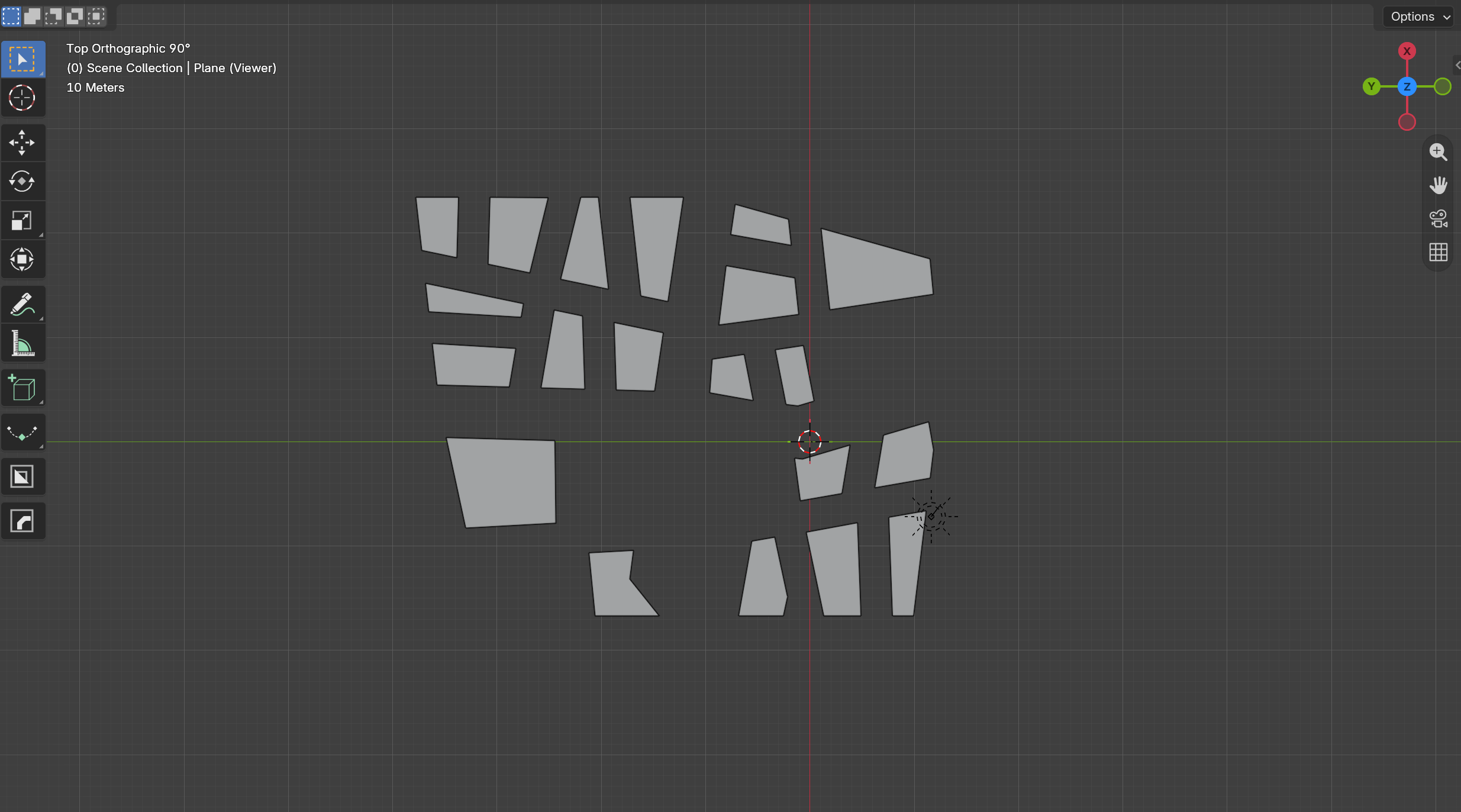
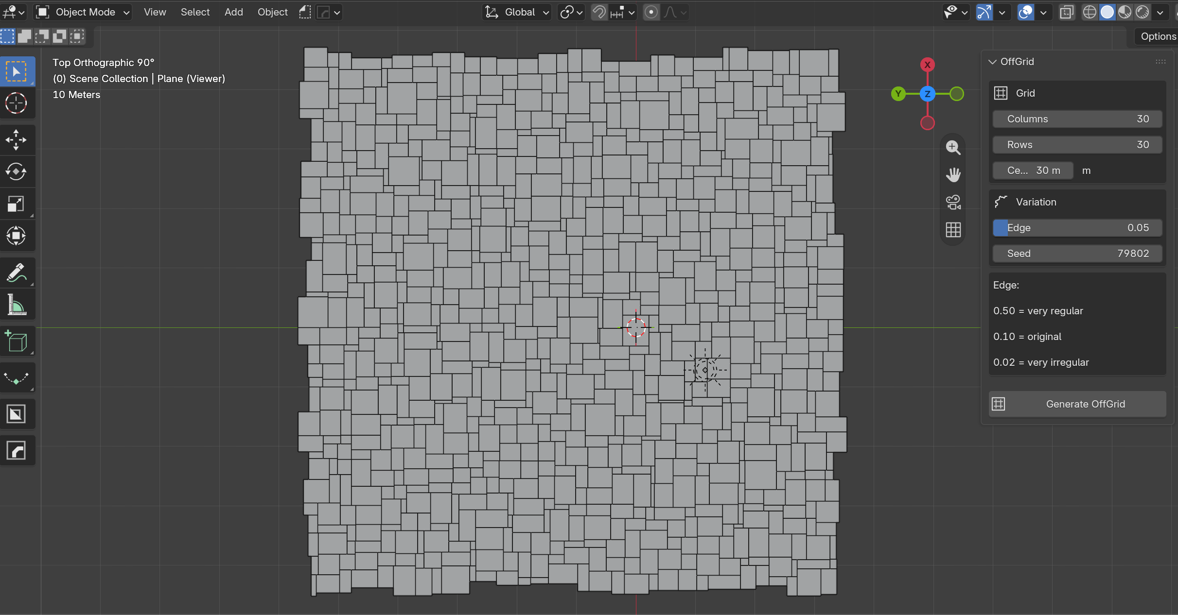
    • edges are main roads (created by insetting the initial mesh faces by a specified offset)
    • set-up further divides the inset faces into smaller city blocks until they reach a specific size and
      parcel to building floor area ratio (I can specify those parametricly). I chose the repeat and for
      each element zone for this, it is not the fastest but allowed me to do the division recursively.
      Maybe there is a simpler and better way of doing it, but I couldn’t come up with anything other.
    • the new city blocks are inset so between them are created new, narrower roads, which adds a
      nice real world hierarchy to the road system I think
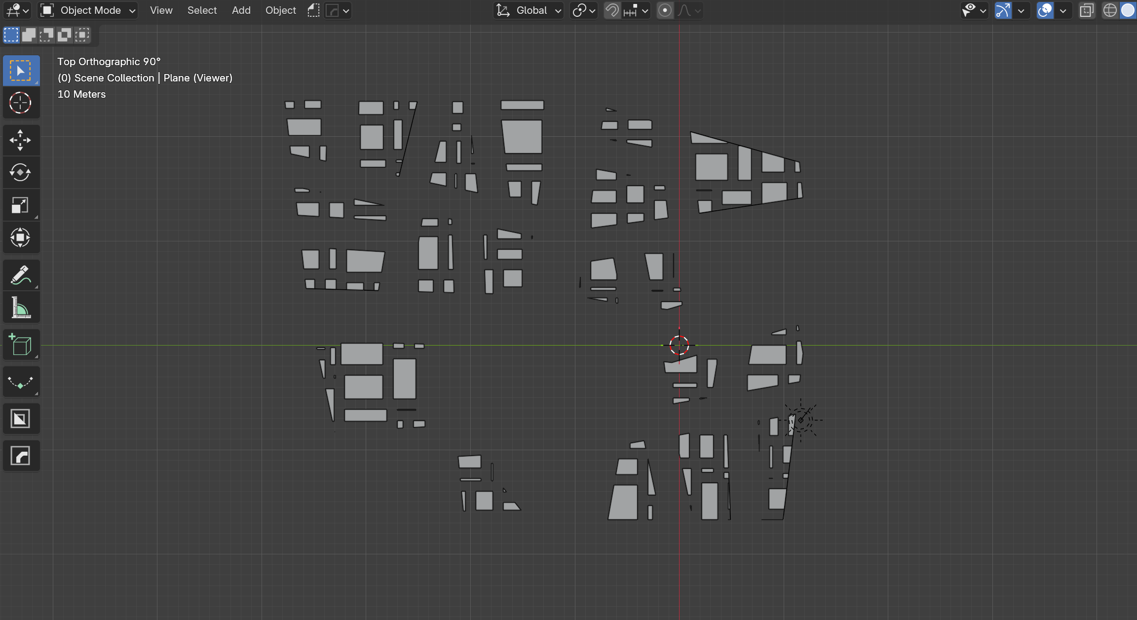
    • label the output city blocks (mesh islands) and put them into categories (medium, small, non
      built) - the medium blocks will have buildings on their borders and in interiors, small only on the
      borders. Non built - are edge cases that have weird shape or are too small and would lead to
      weird behavior later on.

b) Basic buildings outlines creation:
- Convert the created city blocks into curves, offset their start and end points so that they are not
on the corners of the curves
- Subdivide those curves into random length that is a multiplication of the module width (for
example 3m). It will allow me to later on extrude the base of the building to create proxy mesh
for instancing designed and modeled in 3d kitbash facade elements.
- For each curve create building ID for later - Duplicate and offset the curves by the specified
building depth distance with some random variance, label them respectively front and back by
adding named attributes (booleans)
- Create and set position of side curves - add labels

In this way I can have pretty well defined all sides of the buildings that will later on help me instancing different elements on them depending on their orientation. Easier and more reliable than using normal comparison in my opinion.

c) Inside buildings:
- by subdividing parcels labeled as “medium” I can later on use basic shortest edge path set up
to create selections for the interior buildings
- I mark those edges for later with a named attribute

d) Create proxy meshes with the random floor number per building and a procedural rooftop:
pretty straight forward I think, but again I used a repeat zones and for each element zones for the
extrusion. The problem is - now they are nested withing groups within groups and that is pretty
heavy and slows down the whole set up. Maybe there is a faster and less computation intensive
way of doing it, but for the life of me I couldn’t come up with anything that would work on per
building scenario. It was important, because in this way I can also create procedural rooftops for
each building and place it at a proper height. Also I can specify different heights for different
buildings (for example buildings on the main wide roads can be bigger, while the rest can have
different height etc.) and add ID for textures or kitbash models to instance on faces of proxy mesh.

So this is the current stage of the whole project. Next I think I will try and work on optimizing it and test in edge case scenarios. Then divide it into a couple of smaller geometry nodes set ups responsible for each stage in more detail. In that way I possibly will have more creative control over each city block and buildings in it. After all I do not want the tool to dictate my designs (I hope haha).

10 Likes

An update on the interior courtyards buildings.

So the problem that I faced is how to replicate this type of urban composition (Paris, haussmanian architecture):


While the divisions by the roads so far are kind of similar in my node set up, the interior divisions of courtyards and interior buildings were hard to do.

I made a couple of attempts:

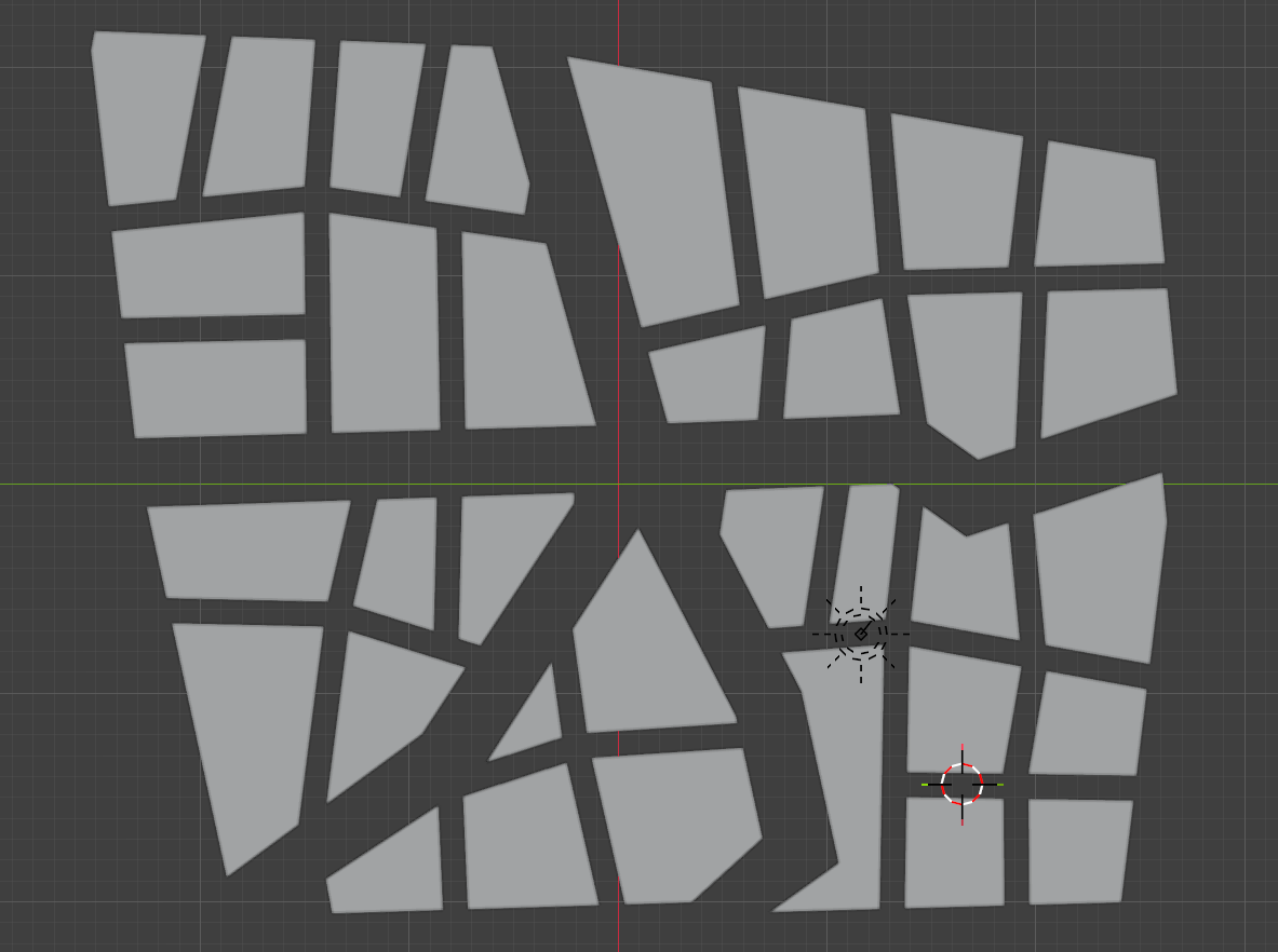
  1. Using grids to divide the interior spaces into curves and use those to create building proxy meshes.

The division set up:

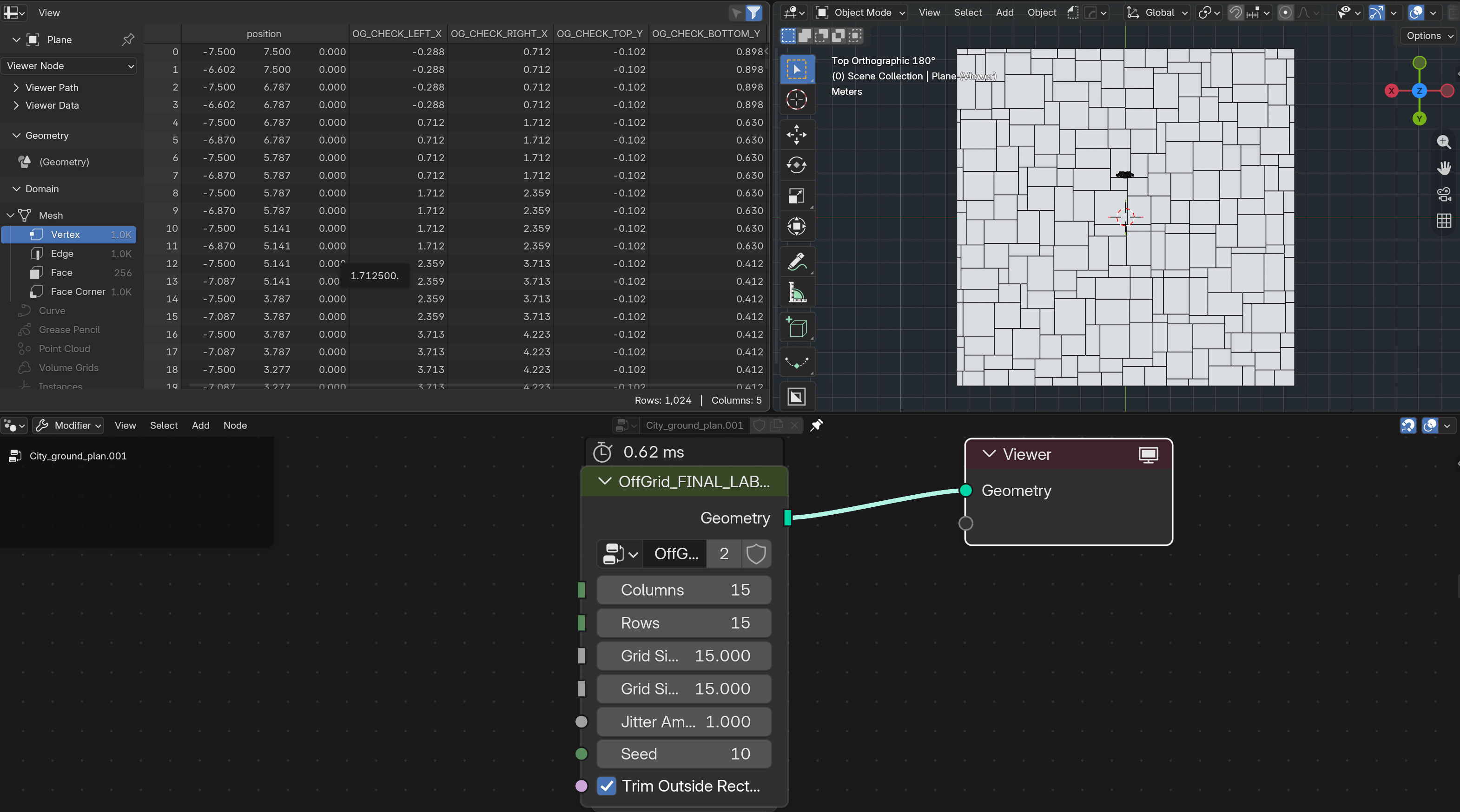
  1. Using a grid with random delete edges set up, the left edges are converted into curves for creating building proxies, a rather quick and decent result. More organic than just a grid:

  1. Similar to the previous one but with the shortest path selection to chose edges:

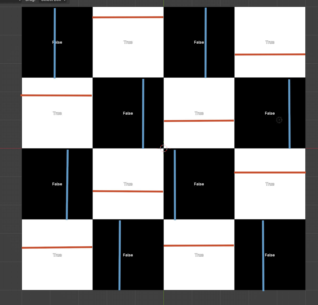
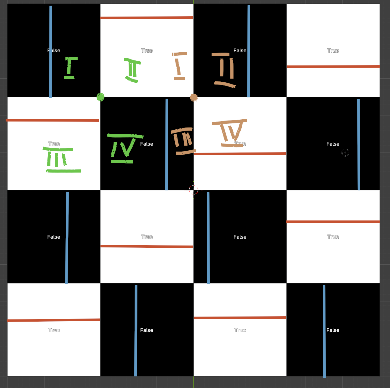
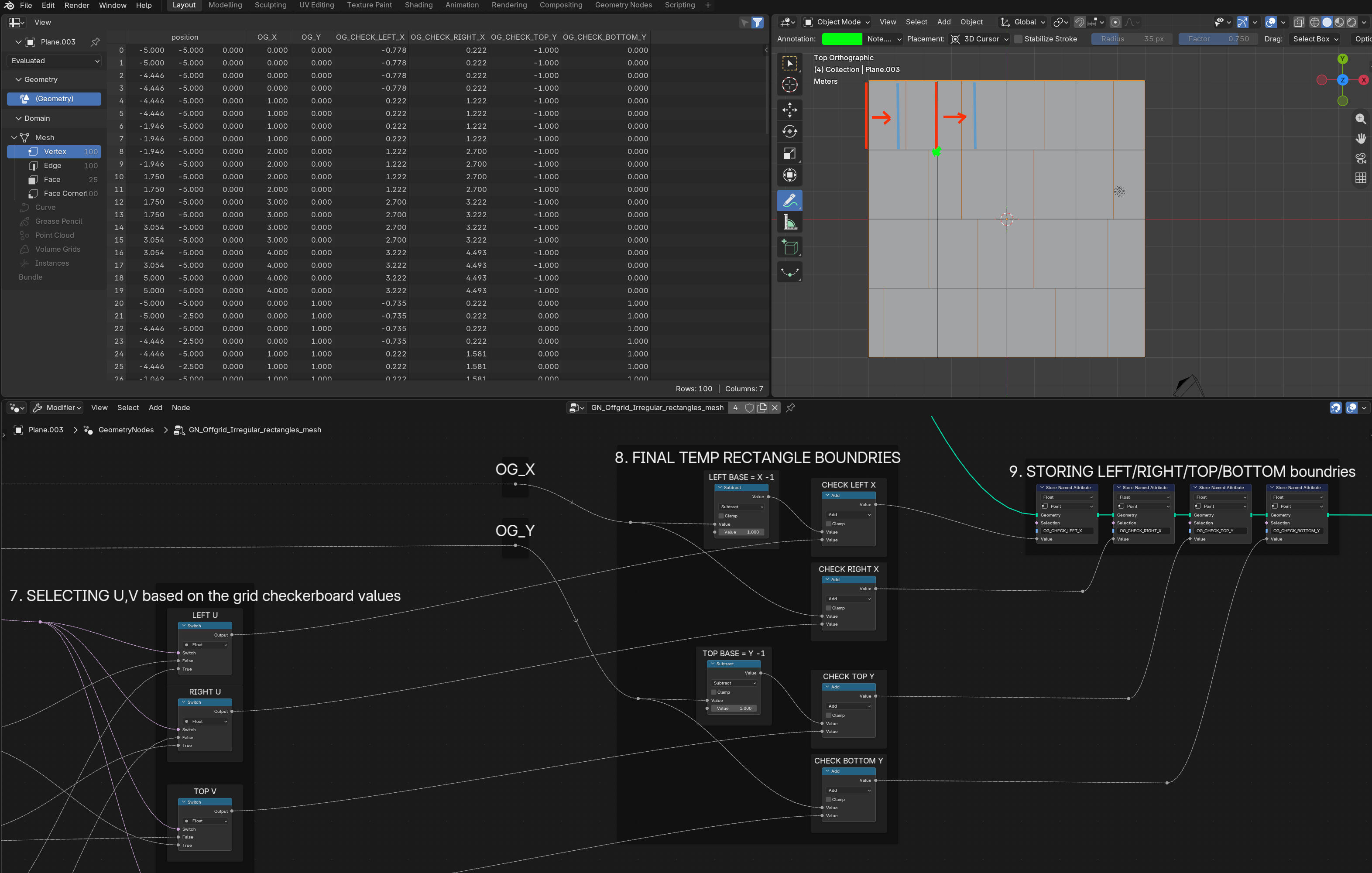
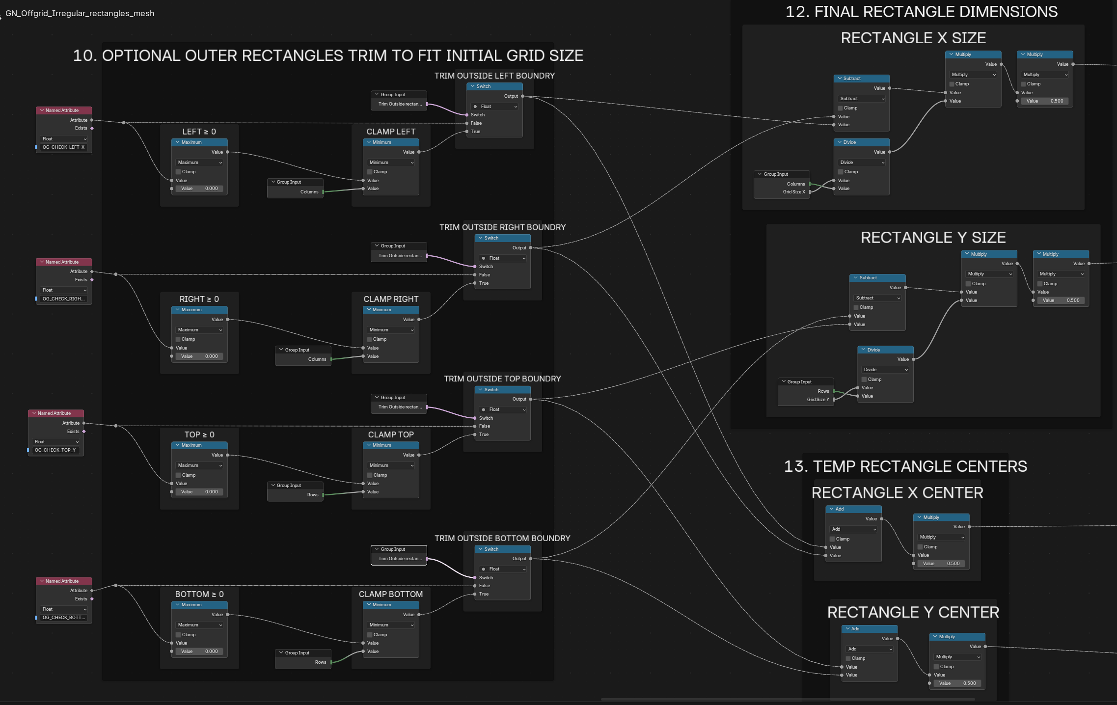
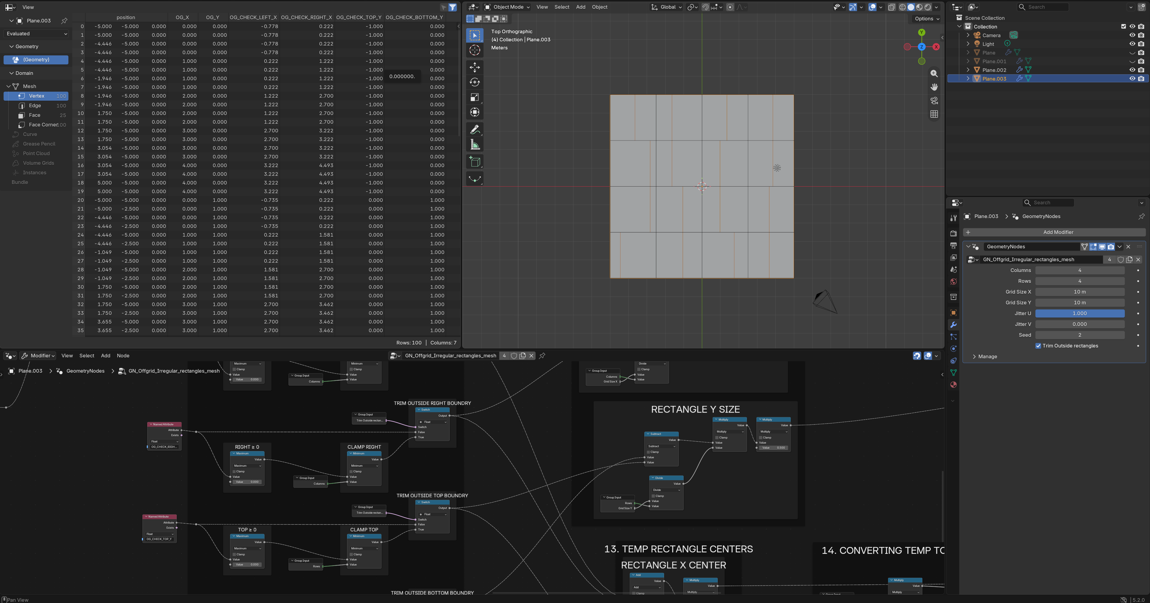
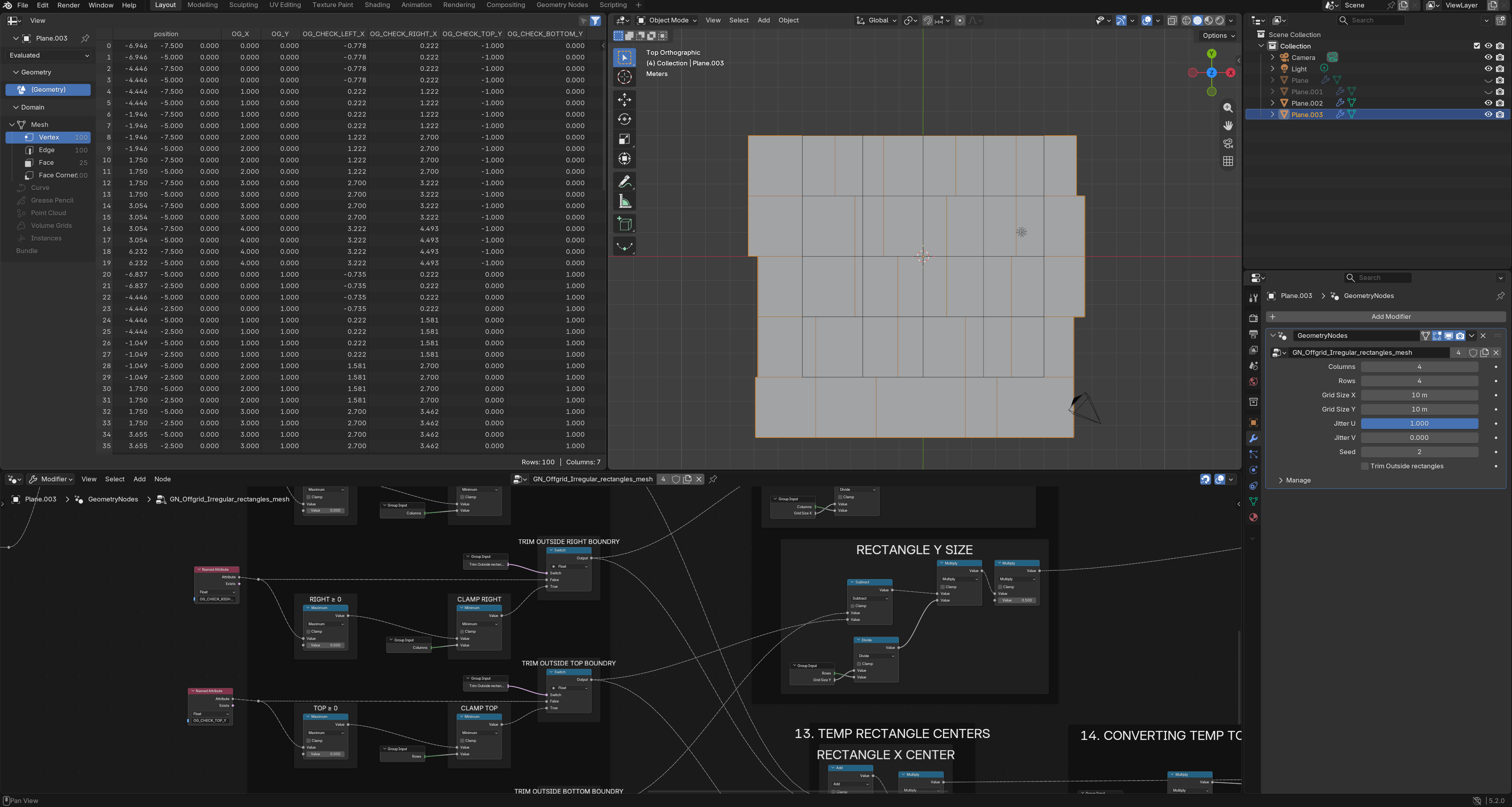
4.Last one, most complicated, incorporates a modified matrix set up, that I’ve learned from a tutorial BCITY by Mike Hodgetts, to create irregular grid that later on is used as a cutter in boolean operation with the base mesh to create a more organic and closed interior courtyards composition - more similar to what I had in the ref:

The last one combined with some random delete seems to create rather good results. Probably more tests are required to nail that look. Or maybe I will need to rethink the whole set up altogether. If anyone has any suggestions or ideas please feel free to share.

Thanks for reading.

5 Likes

I didn’t read all the details, but that looks pretty good so far ! I’ll keep an eye on the progress !

1 Like

Thank you! Yeah, it’s a wall of text hahaha. I’m new to the forum so I don’t know what format of presentation is best.

As for the project - I’ll try and update the topic as I work on the geonodes setup. I consider it a very early wip and more of a proof of concept thing at this stage so probably a lot will change as I experiment and learn, so all the feedback is welcomed :smile:

1 Like

I think walls of text are ok, forums are good for that ! and I tend to do that as well, it’s just that I wasn’t in the right mindset to really read carefully and thoroughly, especially when it comes to tech stuff I need a mind completely available hahaha !

Anyway, I subscribed to the thread so I’ll follow your progress and see if I have stuff to add. I’ve looked into similar stuff even if I didn’t tried city blocks yet :slight_smile: I live in paris also so it’s two reasons to look at that project :smiley:

Good luck with it and see you around !
Hey, thanks for the reply. Yeah I totally understand, I’m similar I need to have enough energy to read through technical stuff.

I’ve seen a couple of your projects and I must say that you are a magician. I remember reading through those topics with buildings and railways generators. Super interesting stuff for such a newbie like me. Thanks for sharing!

1 Like

Thanks a bunch ! At some point , studying hard and diligently pays off ! You’ll definitely get there if you keep practicing ! It’s great that you share stuff as well so we can inspire each others !

1 Like

Update.

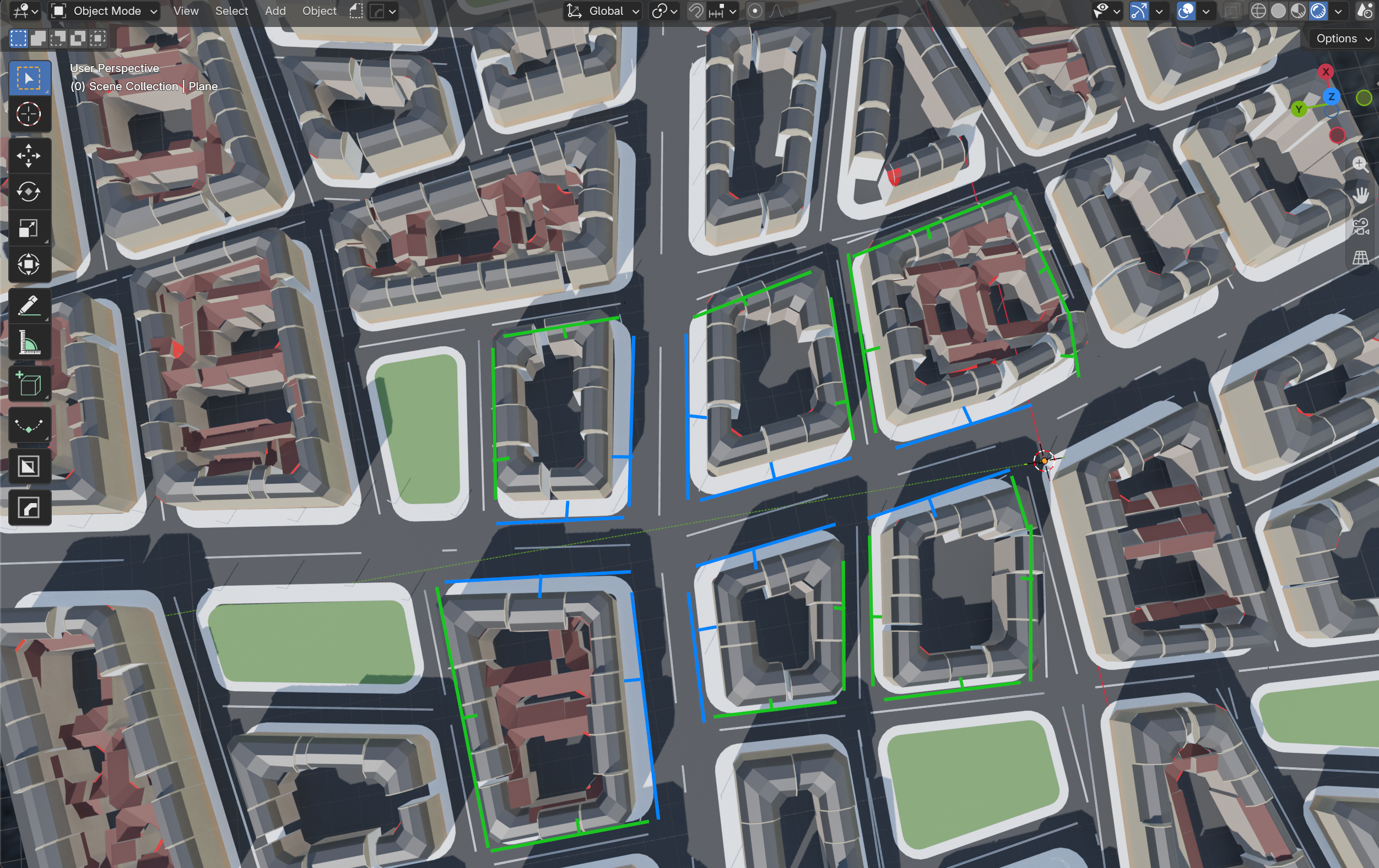
So today I was working mostly on some minor stuff like very basic street markings and adding some guardrails to more prone to odd behavior parts of the building meshes generator.

I think that my initial idea of ground plane division into main and secondary streets and city parcels between them might have been not so optimal. I spent a day trying to create axis for roads and fix those curves directions or find ways of trimming them proportionaly from both sides. Another thing was breaking those curves at the intersections and crossroads.

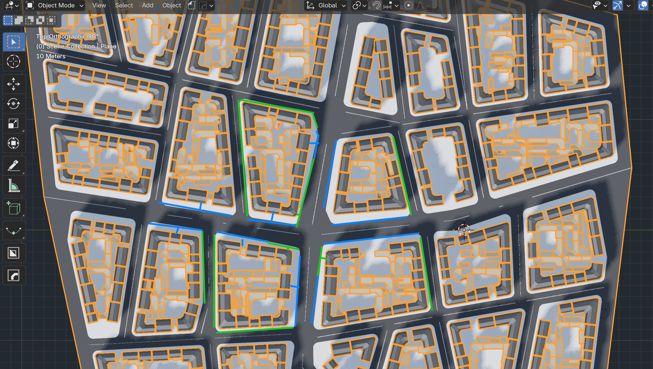
The secondary streets are just main city block outlines copied and offset by the half of the street width and then trimmed at ends to create spaces for intersections and later on points for crosswalks. Since the curves were having random directions and random tangents I was initially trying to create a clever way of reorganizing them (making point index 0 near the main road, then the end of the curve the remaining index) but I realized that it was not needed and simple merge and split edges with trimming by the same amount from both ends does the job well.

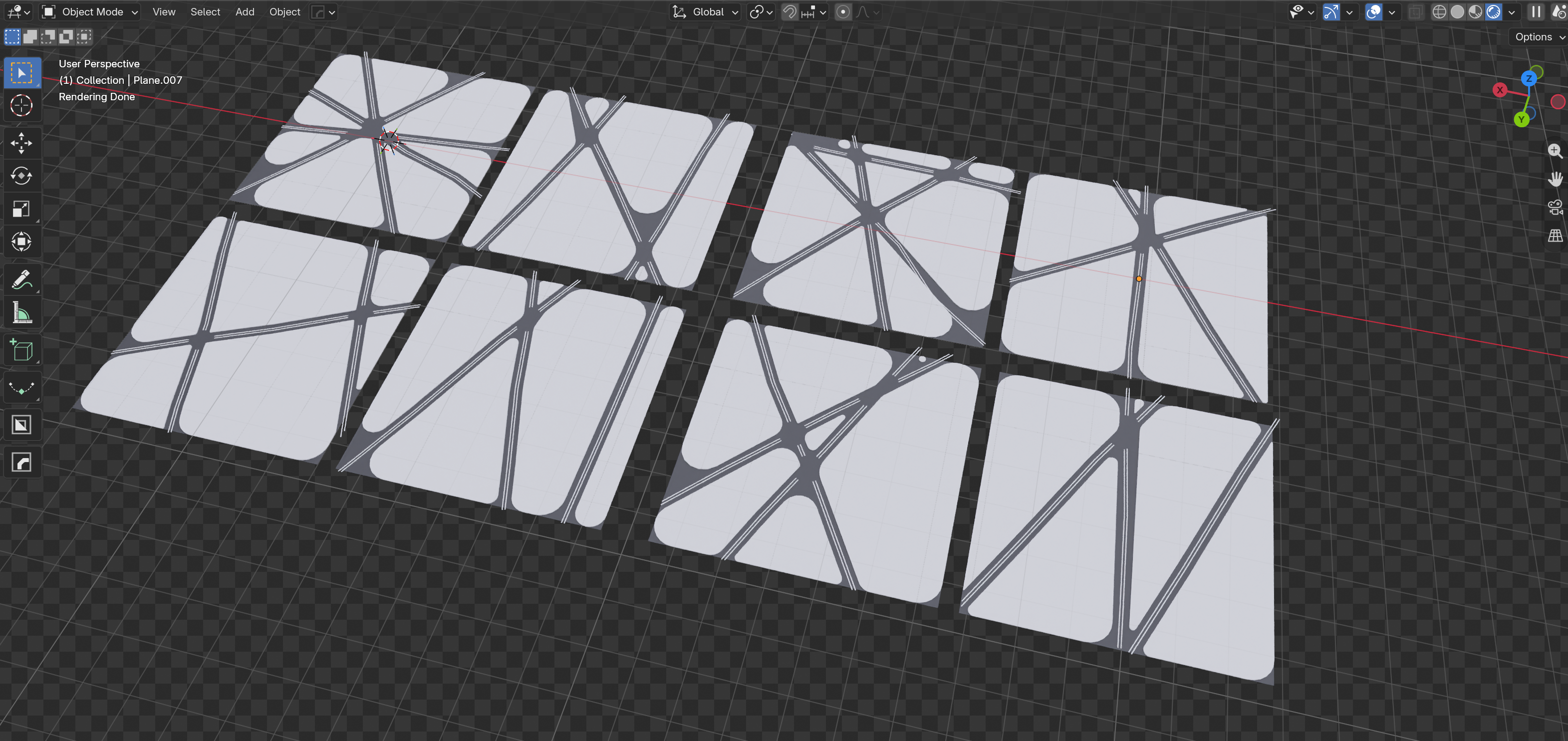
The main roads were tricky tho. I used an “inset” geo node setup for initial offseting of the mesh faces and then subdivide those new faces into city parcels further.

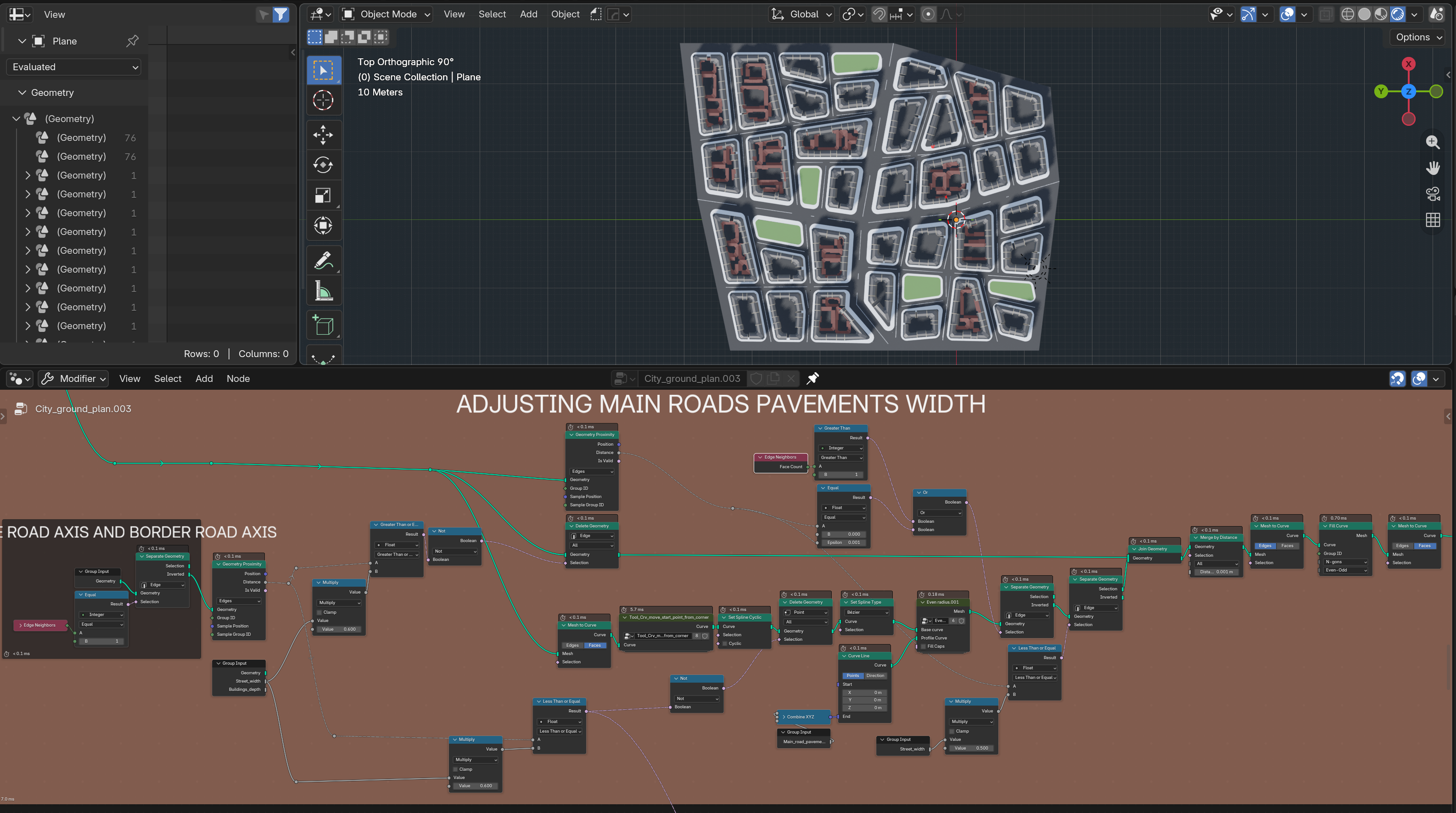
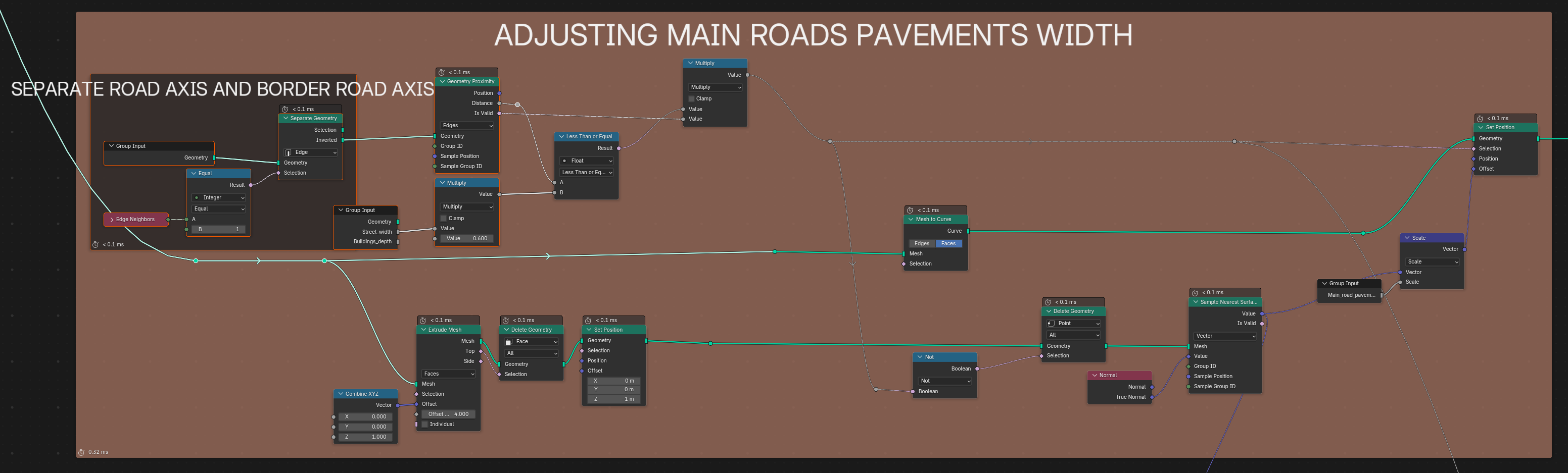
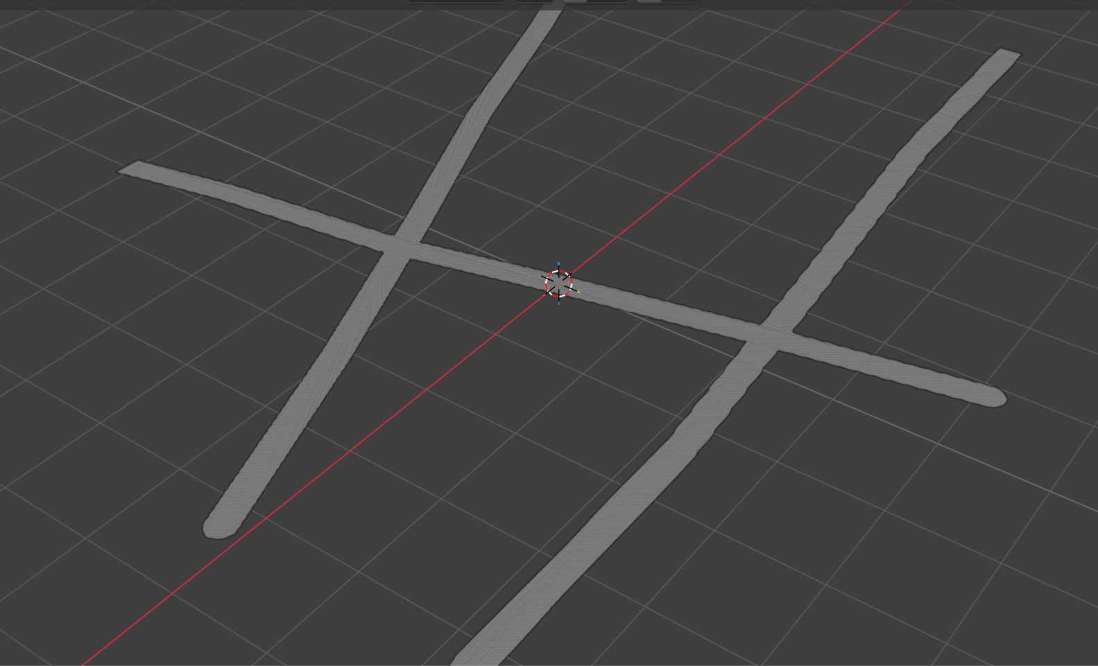
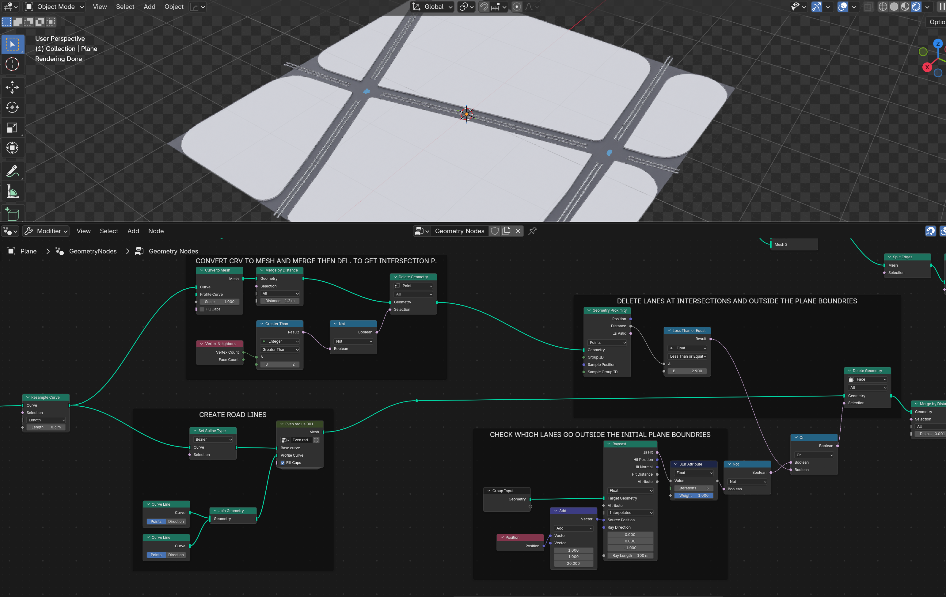
It meant that while I had the initial big roads axis readily available I did not have them separated into segments that correspond with the secondary roads ends and intersections. I had to figure this out and use some geometry proximity with converting between mesh and curves with resampling and later on merging to get points at intersections of the roads. Then I used proximity to those points to delete parts of the road markings (that were made by turning curves into meshes)

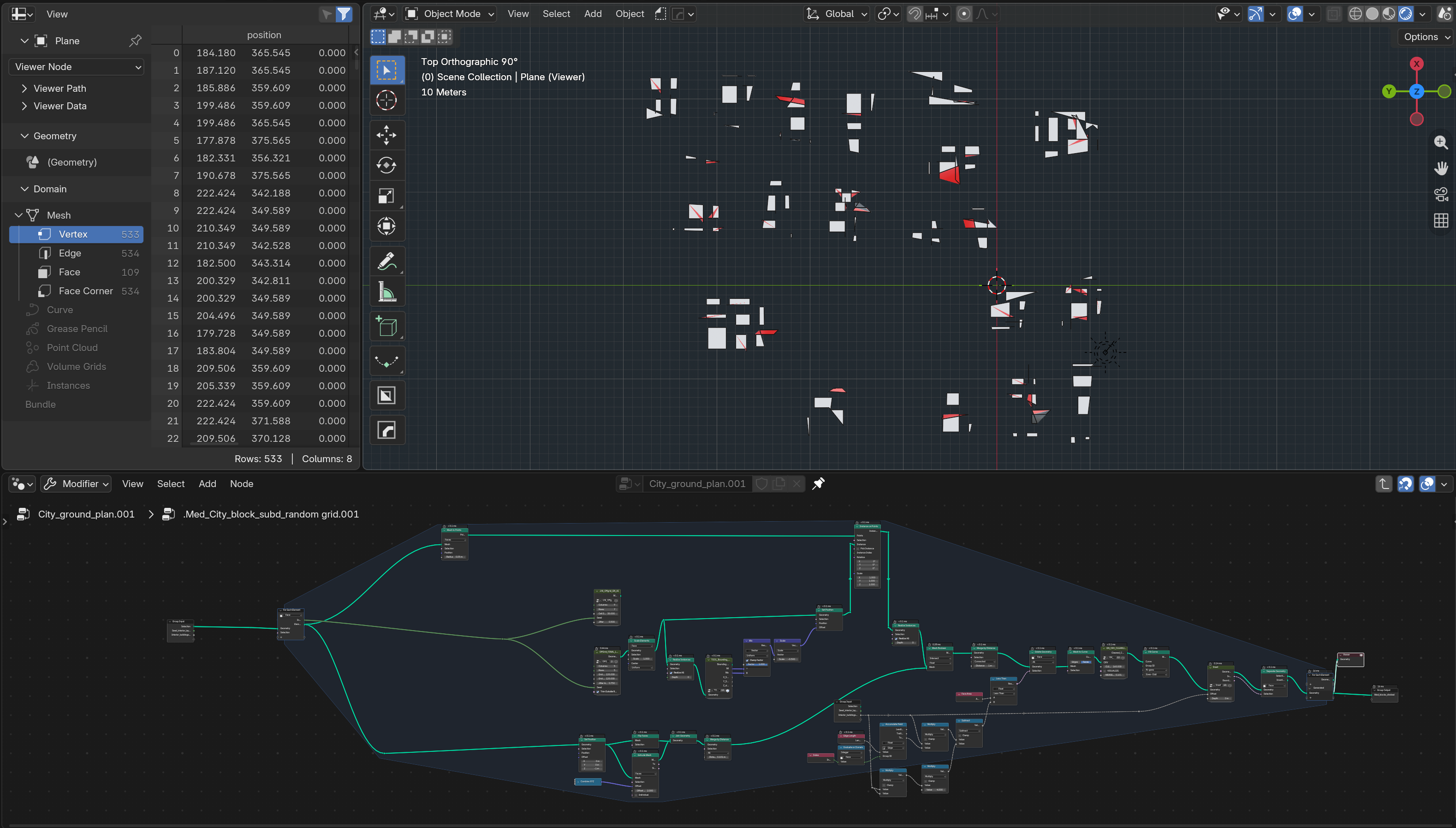
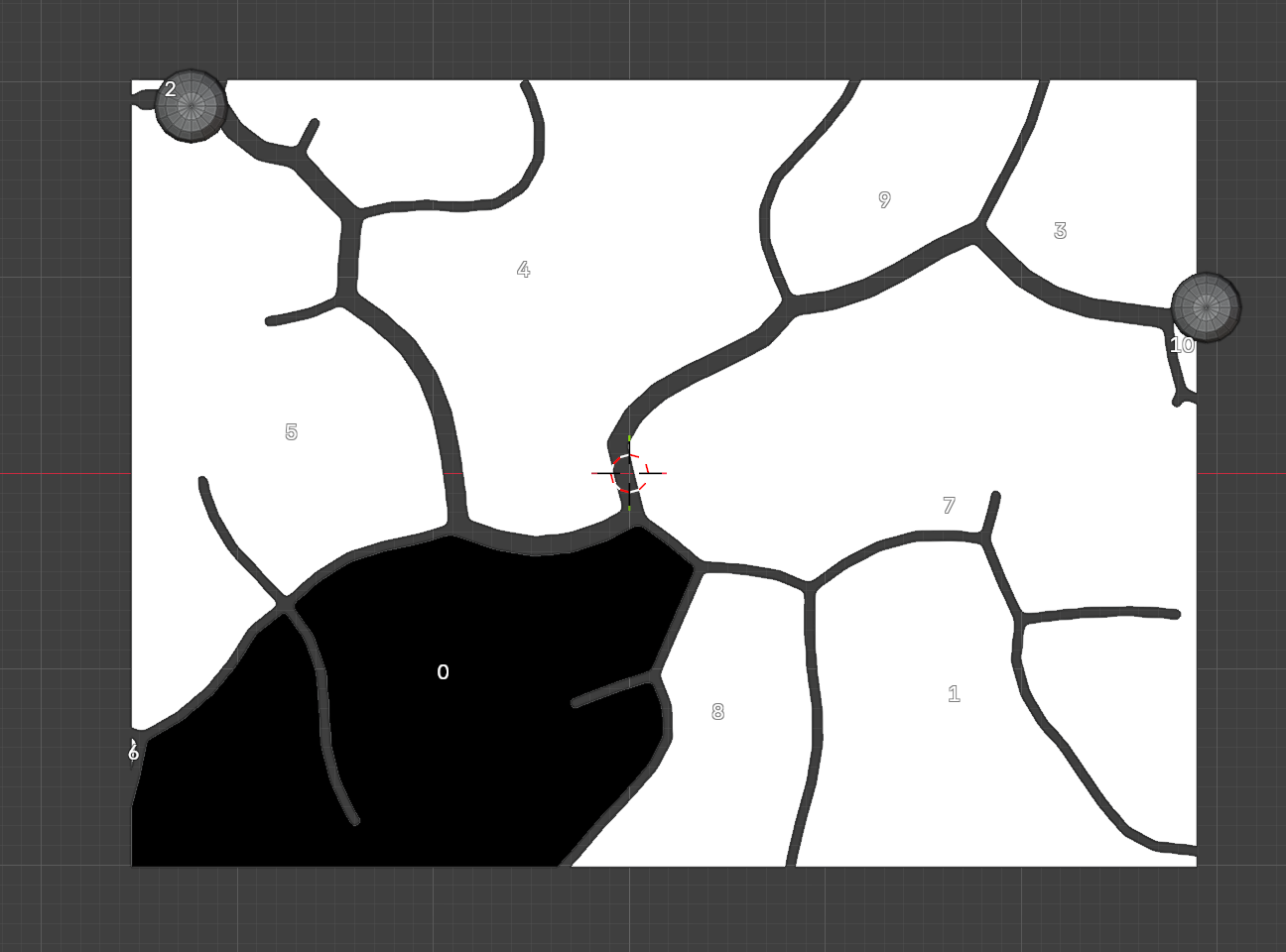
Next was a gate logic to filter out the odd or problematic shapes or the interior courtyards parcels used for interior buildings.

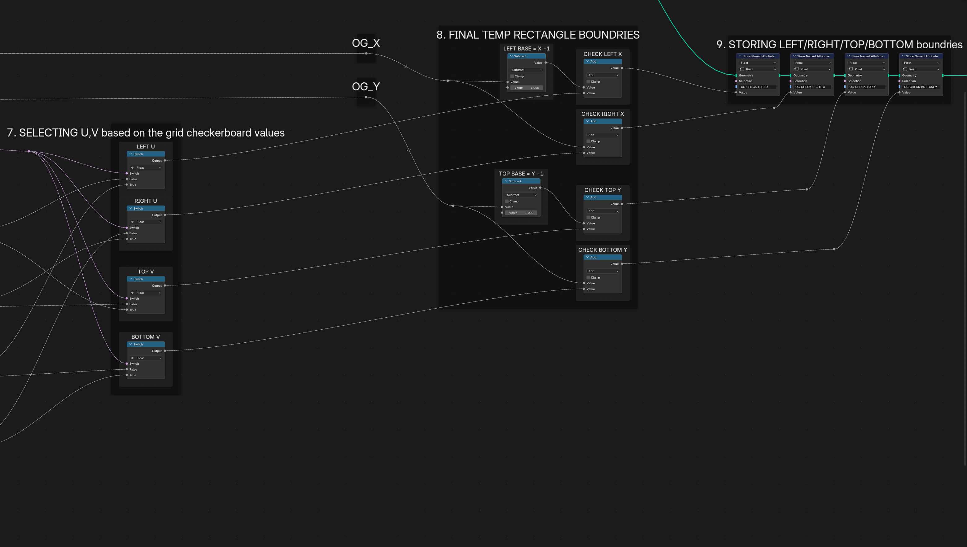
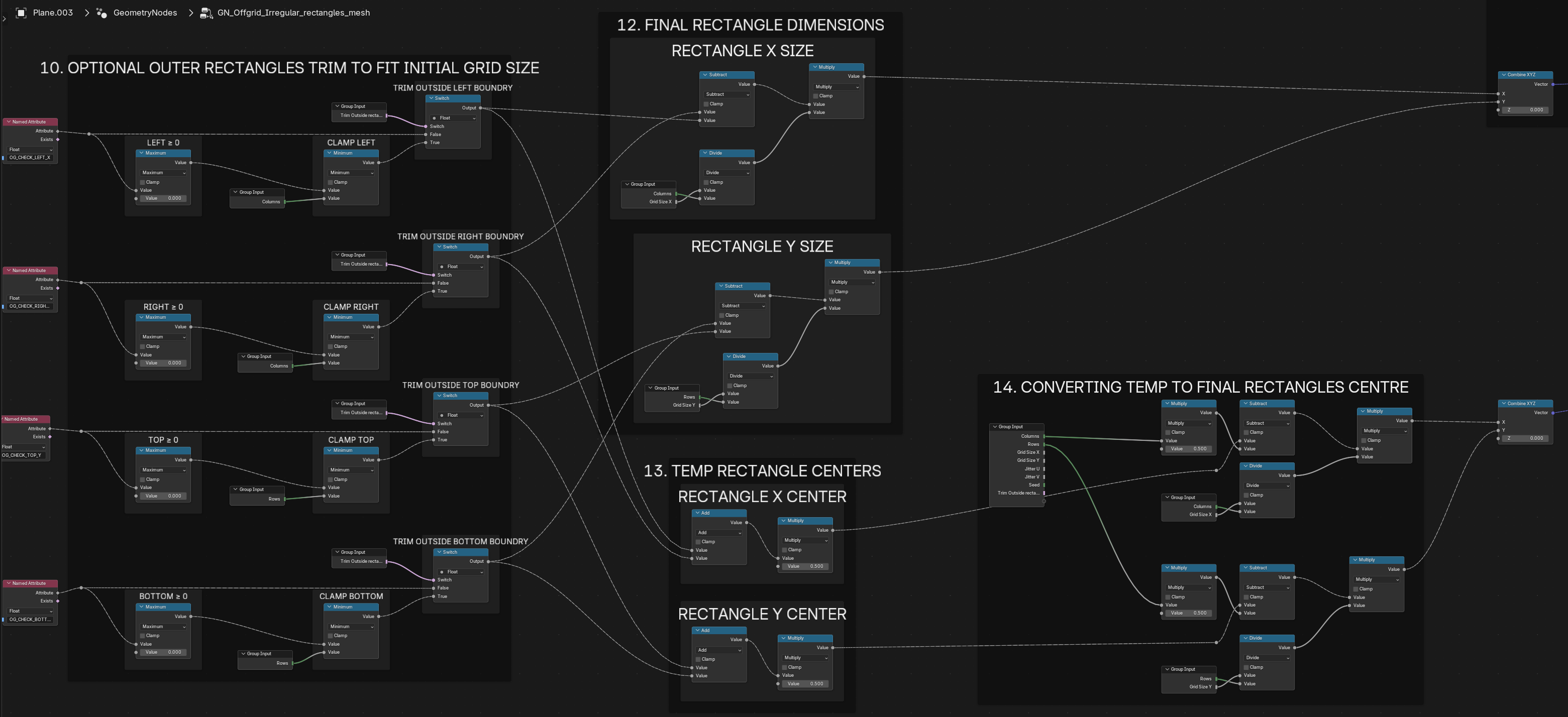
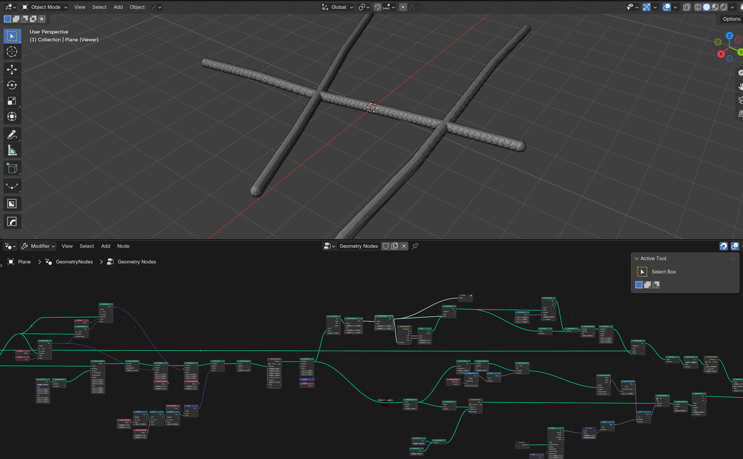
It’s mostly filtering out faces with sharp angles, too small surface area for building plans or that fit characteristics of triangles or problematic simple geometry shapes. I made a utility helper node group for that:


A mini spaghetti monster.

So thats that for now. Thanks for reading! If you have any suggestions or if anything is presented in a way that is difficult to understand please let me know.