CRT Moire Pattern

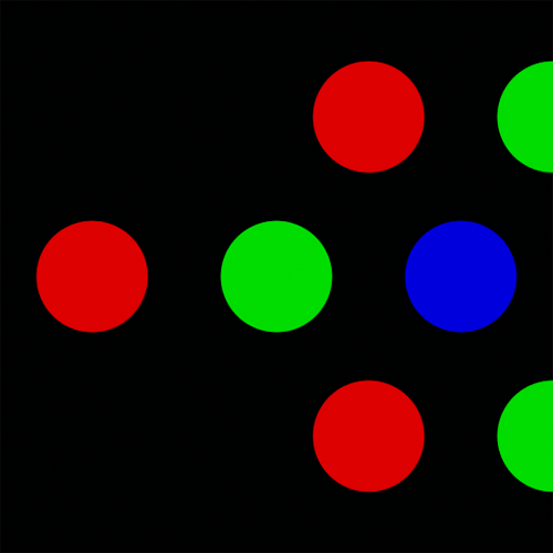
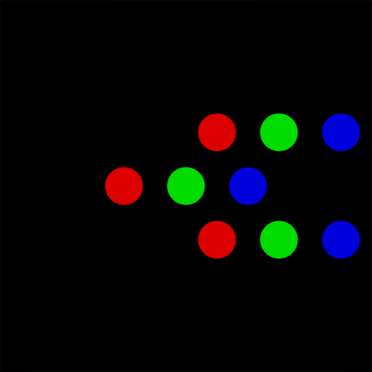
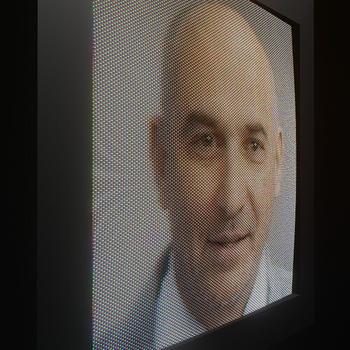
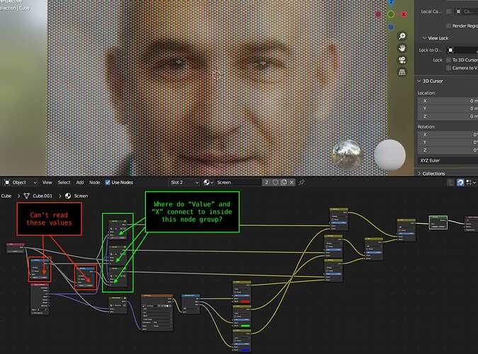
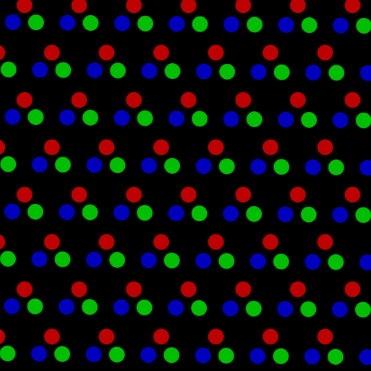
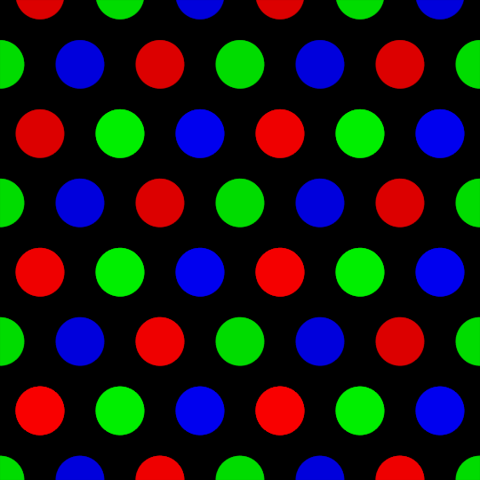
I’ve been playing with a CRT moire shader off and on for a while. Basically a triangle of three red dots, then three green dots offset, then three blue dots offset, and then, ideally, just tile that block.

I got something pretty close using Geometry nodes, but it creates it as mesh or curve objects, and I want it as a material.

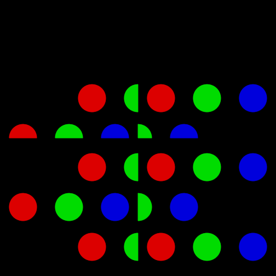
I can make the basic form, but I get lost trying to tile it afterwards. The pattern clips, and I need them to overlay each other.

I could tile using a modulo or a voronoi texture, but my pattern object doesn’t output coords to remap. And when I try doing fancy maths at the start of my chain, it again clips.

Anyone have any suggestions?

CRT Moire.blend (124.3 KB)


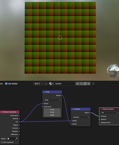
…So, the technique to tile patterns in the Shaders is to create a repeating coordinate-frame…

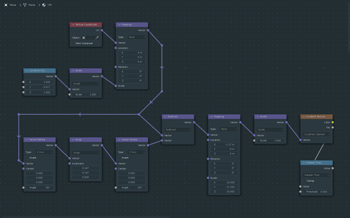
This is how you make one that just makes a coordinate grid:

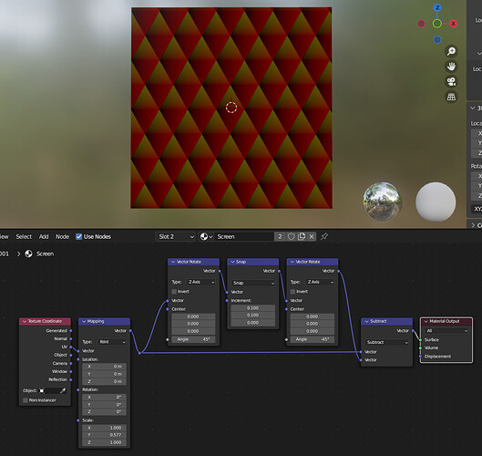
…this is a hex-coord grid:

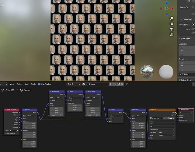
From there you can do coordinate based things like map images… eg:

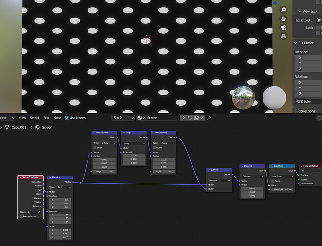
…or make dots by checking distances (here using sqrt(3) as pre-scale):

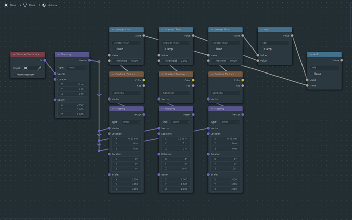
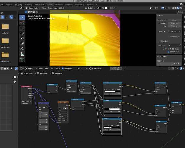
…from here you have all the bits you need to make the CRT pattern; you’ll just need 3 copies of something similar and you want to pixelate your source image so it samples better:


…with those numbers in the pre-scale and post-scale being 1/sqrt(3) and sqrt(3) respectively (as an exercise, draw out a hex-grid and see if you can determine where those ratios come from)

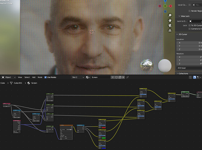
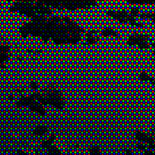
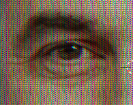
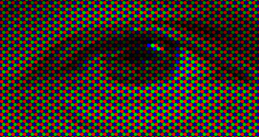
Finally, its just a matter of adding the 3 patterns together and mixing in the sampled colors - you should have something like this:

Good luck.

6 Likes

Did the first 2 patterns but the dots one did not work!

is there something missing?

thanks
happy bl

Thank you for such an extensive breakdown.

It’s very helpful and interesting. One thing I picked up is using multiple mapping nodes to tweak the group as a whole, which is already useful.

I gave your method a try, and also hit a wall. I tweaked your grid layout (image 5 in your post) as follows:

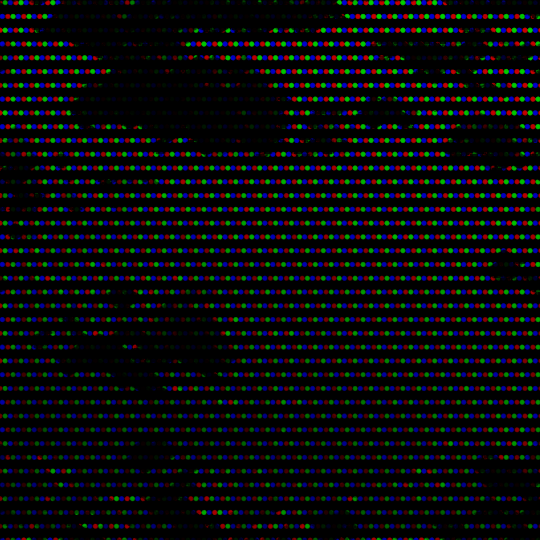
to get the perfect round dots I need, and at the end of the process, I got this:

It’s an interesting “old broken TV” effect, but as you can see, it doesn’t match your work. I was able to move the dots into columns, but there’s a huge gap between the rows.

Clearly, I was unable to suss out certain parts of image 7 from your post. Namely:

and that’s probably where the magic needs to happen.

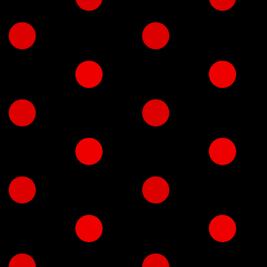
I’ve been able to offset the patterns on X, but what I need to do is offset them along a 30 degree angle.

I messed with it a bit using more mapping nodes, and was able to get this far:

but the row gap is still there, and it breaks when I scale it.

If you can provide the data that’s unclear in your image, it would be a big help in duplicating your results.

Returning to my original attempt

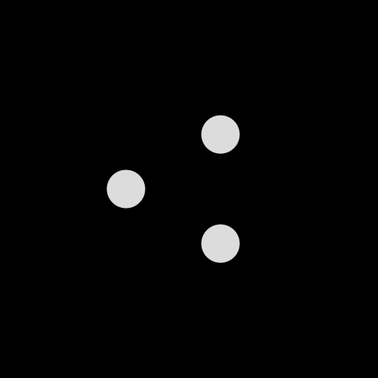
My method was to offset the dot and rotate two copies at 120 and -120 degrees to create the triad.

Then the trick would be to tile it thusly (your tip about 1/sqrt(3) came in useful here, BTW):

and since this hexagon pattern is rotated 30 degrees from the one in your example, it’s simply a matter of moving each copy along X to produce this:

I got as far as this for the triad before I hit the wall I wrote about in my original post:

I grouped it and offset multiple copies to create the image above. I’m sure you’re not surprised to hear it took a lot longer to render than your version.

I am convinced there is a way to do this same thing mathematically, but as of yet, it still escapes me.

I’ll keep working on it. :thinking:

Update

I kept working on it, and simply eyeballed the offset for each color until I got the correct (-ish) positions.

To wit:

If you look close you can see that the image pixelization isn’t matching the size/spacing of the hex dot grid. Still too short on the Y axis.

I haven’t figured out that particular fix, but when the dots are small enough, you can’t even tell.

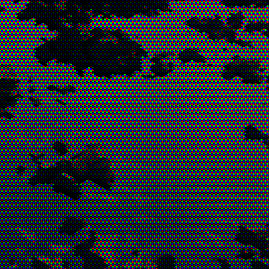
Although the overall rotation is still off by 30 degrees – you can see how the interference pattern stripes vertically and horizontally, rather than diagonally – I think this solution is close enough for Jazz, so let’s mark this topic as solved! :+1:

2 Likes

Well done for persevering and figuring it out. I hope you’ve learnt a lot!

Attached is a refined technique:
RGB Screen_2.1.blend (518.4 KB)

image

image
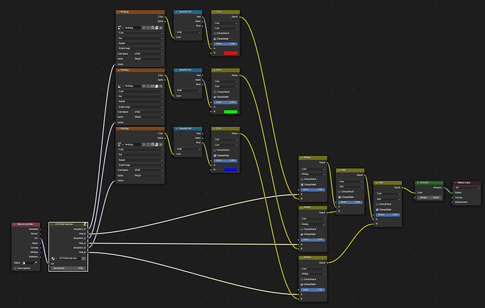
… this one is a bit more involved in that it does 3 sample passes to ensure only sold dots, and the dots are perfectly circular.

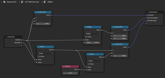
If you check inside the .offsets node-group you’ll see sqrt(2) and sqrt(3) make an appearance to adjust for the circle/dot generation (Specifically Dot Size Adjust to make the circle perfect).

I enjoyed doing this exercise and its taught me that Blender’s Shader nodes have a lot of room for improvement. Features that Geometry Nodes editor has that the Shader editor is missing include the ability to specify images as node-group inputs. Without that you are currently not able to make a totally reusable CRT-scanline node-group that you can drop in and then just select an image source. To reuse this you’ll have to manually go into the material and select a new image 3 times (for each sample-source)

Credits: The packed image is from https://thispersondoesnotexist.com/

Nice update! Thanks for correcting the angle – that vertical/horizontal moire striping was irksome.:weary:

The only tweak I made was to the .CRT RGB Dots Gen group. I changed the X-Offsets from positive to negative numbers so the dots now go R-G-B from left to right.

I’m playing with the size of the dots to get the exact correct Lochmaske Shadow Mask scale, and searching data on old monitors and Trinitrons to figure out the right overall X by Y density of dots. (525 lines means what now?)

And then I’ll need a “coated glass” effect of some kind to give it the right softness, blur, and distortion. It never ends, does it? :man_shrugging:

You’re right that this exercise exposes some of the limitations of the Shader Nodes editor compared to the Geometry Nodes editor.

In addition to what you mentioned, being able to create/expose attributes is a great feature of Geometry Nodes that I’d love to see in Shader Nodes.

In my GN setup, I used them to separate my image into R, G, and B plates, had the Shader/Material posterize the greyscale values for each dot, and then combined the plates back into RGB in GN.

So cool. :+1:

I’m still a little unclear about the scope of Everything Nodes, but it would be brilliant of they brought things like Attributes, and discrete Random Value and Boolean Switch nodes to the Shader window.

Anyways, thanks again and Happy 2023!

Quick followup: I just found another approach to this on Reddit.

Another Followup: And if that wasn’t enough (and by gosh, don’t you think it ought to be?) the latest chapter in this series about UV-based shader node grids is all about CRT and monitor patterns. Like, I can’t even…

1 Like

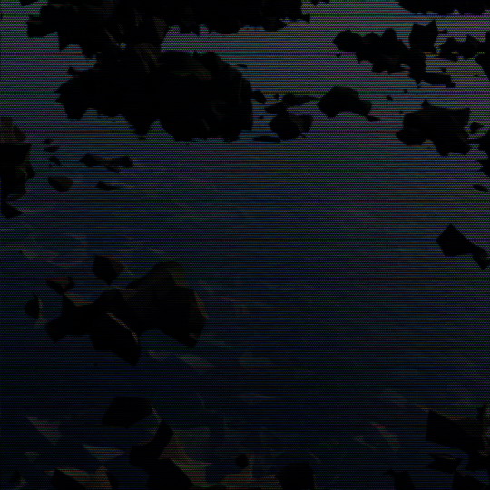
A similar approach I used here for more of a scanline look.

1 Like