Hi, I’m working on a test project which is my first proper attempt at blender and it’s unique way of working.
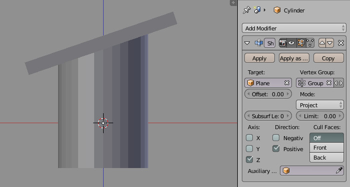
It’s a simple multi-level garden and I have a wall which slopes from the top-level to the mid-level but also curves (viewed in plan) and I’m wondering how to go about modelling this in Blender. In the below screenshot you can see the reference DXF import’s to see the area I’m trying to tackle.
Looks like a simple curve modifier to get the bend. Then edit mode proportional edit scale down till you get the slope you want.
You could even model it as a 90degree corner with simple geometry then apply scale then select the two edges at the 90 and Ctrl+b to bevel them to the width and curve you are wanting. This will help as well keep the vert count lower. Then you can add geometry as needed.
I watched a couple of youtube vids showing the curve modifier, looks a bit of a trial and error approach from what I could tell.
I gave the latter option a try using proportional editing on 2 end vertices and the 2 at the 90° degree corner and it did seem to work though I’m not sure how accurate it is. I’m not convinced the geometry shown in the DXF’s is even correct, seems very tight to achieve the curve.
If I was trying to model this in other software, I would create the 2 profiles (start and end) and a 2D path then loft the profiles along the path. Does blender support this workflow?
There is Ctrl-LMB add vertex and edge from previously selected vertex; then there is Solidify modifier you can apply to the vertically extruded vertex-traced plan.
For even more precise round corners add circle you can set diameter and vertex count. Erase not needed verts of circle.
There are addons allowing to loft profiles, at least two of them.
One toolset from Paul Kotelevets aka 1D_Inc where loft is included is still available here.
Thanks Eppo, I’ll have give that addon a try later tonight.
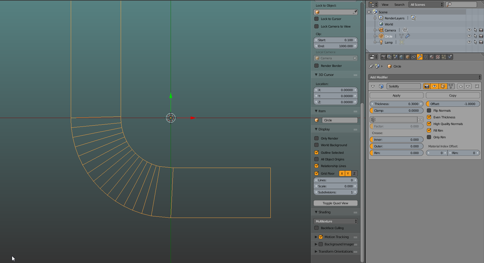
A slight update from earlier using FlyingBanana’s 2nd suggestion, I found bevelling the L-shaped wall corner’s first and then apply the proportional scale with 2 end vertices selected. It kinda works but I can’t be sure if its right:
The internal vertices look strange but they may be correct, I was contemplating changing the Z value of each vertex on the inner curve to match the external but again I can’t be sure if that would be correct either.
What do you mean by “on plane mesh”? The reason I ask is that your gif shows vertices symmetrical below the middle of your extrusion which I was wondering if they were created by another method than the knife tool.
Ahh gotcha, I thought you meant something like that
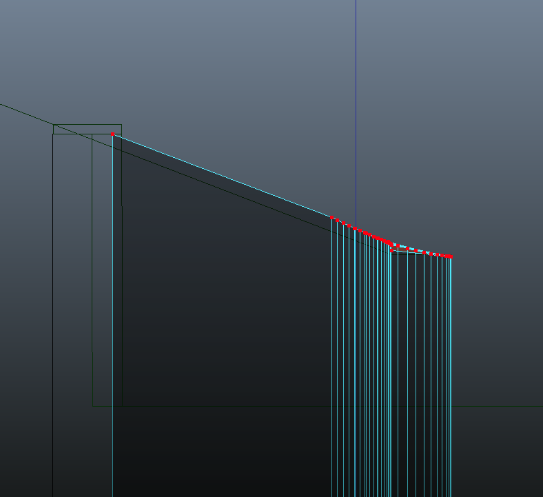
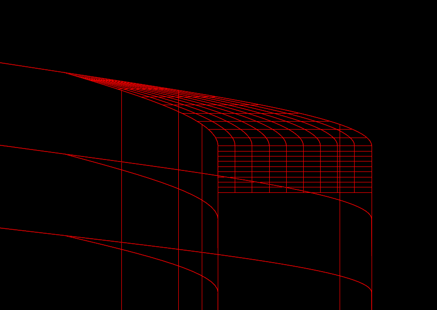
I’ve just done a bit of research and found that the knife method isn’t accurate which is what I was suspicious about with the other suggested methods. The problem is that when using the knife, the vertices on the curve are in a straight line but they should not line up and instead should curve downwards (when viewed in the side elevation)
Unless I made a mistake, I also noticed that the solidify modifier isn’t accurate either. As you can see below, the vertices on the inner curve where it meets the line, they are not perpendicular to the equivalent on the outer curve but they should be and no setting in the modifier allows me to do so.
I know this is a minor issue and maybe isn’t a concern to others but i would like to adopt Blender as a modeller but in order for me to do so, I need to be confident it can produce accurate geometry that I can make in other software.
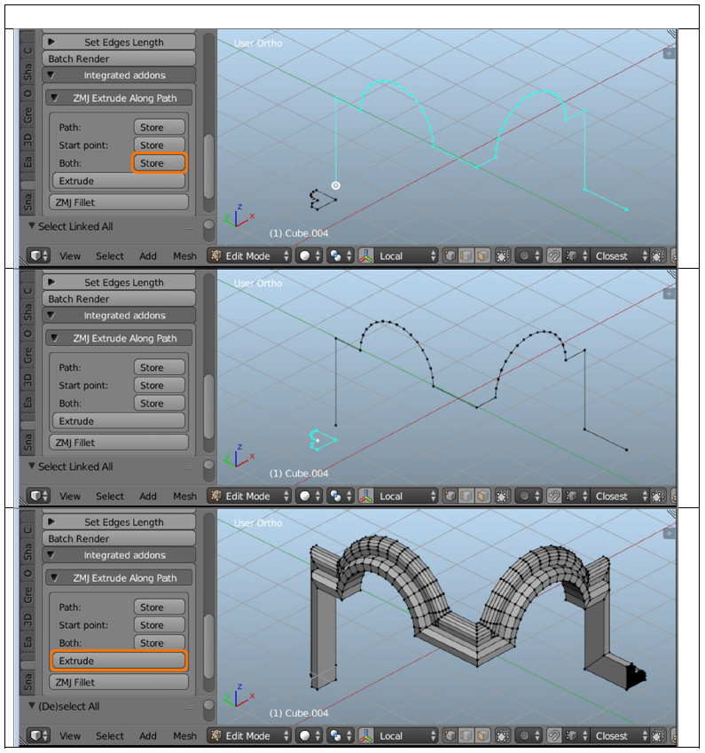
I just downloaded the 1D_Scripts addon but I couldn’t tell from the available tools which option I should be using so I downloaded the ‘1D_Scripts CAD toolset manual’ and looked through what each tool does. It seems that none of the tools work as per my example above, the closest is ZMJ Extrude Along Path which appears to work like SketchUp’s follow-me tool and only accepts a single profile
Yes, there are slight distortions in how solidify works. Or rather the result differs from that one would want in this case. If such errors are unacceptable in your project, well…
I could not find Zmj’s addon so i linked to toolset where this is included. Pita if that does not allow all you want.
Extrude along Curve can use multiple curve segments as profiles (i would think one mesh object could represent multiple of profiles speaking Zmj’s addon, idk); you’d have to go through multiple conversions mesh-curve-mesh though and it has it’s own quirks.
Has there ever been an explanation why it works as it does? I used to do a bit of VBA programming in the software which the example was done in and I learned that whenever any transformations were to be applied to geometry (move/scale/roation etc…), they were computationally transformed into B-Splines (without actually converting the geometry) which allowed for highest possible accuracy for the transform. I’m wondering if the difference is perhaps due to the curve of my blender example is made of segments instead of a true curve and any calculation is based upon the normal of the segment and not towards the radius of a curve.
Yeah ZMJ’s stuff I referred to is contained in the file you linked in your first post.
What is Extrude along Curve? Another addon?
The ZMJ Extrude along Path tool only allows 1 profile:
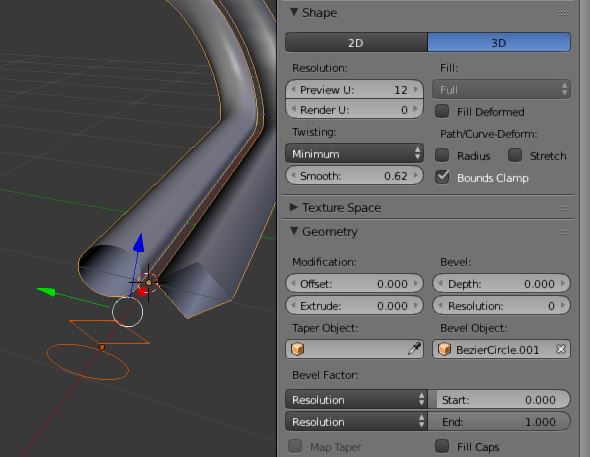
However you’re not limited in what can be defined as a profile. While there’s only one Path, profile can be any mesh you fancy. Or i do not understand what was a limitation in “accepts single profile”.
What I mean is 2 different faces or collection of edges which define both the start and end of the mesh. Your latest screenshot has the same size circle and square at the start and the end whereas what I am trying to achieve is 2 different sized rectangles with the difference being the top 2 vertices moving up/down on the Z-axis as it follows the path.
I’m almost certain I could calculate it manually:
The difference between the top vertices of both profiles is the total height difference
At each of the walls vertices on the XY plane, calculate its distance along the total length of the path as a percentage.
Multiply this value against the total height difference to get the correct Z-value for each vertex and extrude each vertex on the Z-axis to this height.
Faces can then be easily created from the resultant edges perpendicular to the path.
This would need to be done for both sides of the wall (since the solidify modifier appears to be not completely accurate).
There may be a flaw in my assumptions but I’ll probably give it a test and see how it looks.
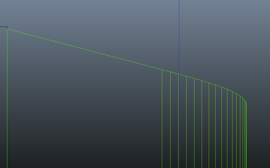
I don’t think its that simple as (if I understand the suggestion correctly) its intention is to align all vertices on a single slope viewed from that elevation (just the same as the knife-cut yields). If you look at what the true shape is, the vertices do not align:
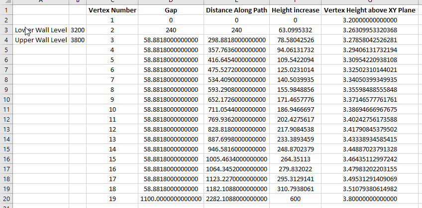
So I finally got around to testing out my theory and it looks like my assumption was correct after all. After drawing out the path edges in the mesh, I created a simple spreadsheet inputting values such as heights of the wall/ distances between each vertex etc… and some formulas doing what I described in bullet points to the get each upper vertex’s height.
Then copy the value from spreadsheet and extrude each corresponding base vertex upwards pasting the value. Its a bit time consuming but after completing 1 side the results look convincing to me.
If I can do this in Excel, then its probably not to difficult to repeat the same workflow in Python if you know what you are doing, however I’ve never tried learning the language so I’m stuck doing it the manual way for the moment.