Lancer, any input given would be golden at this point. I know they still have a lot of work on Cycles left to do, but it would be nice to hear anything that might be usable already.
Sure thing Craig Jones - just back now and was refining / taking screenshots etc.
Here’s it is - not pretty but something to play with. In the attached file there are two scenes; one in Blender Internal the other in Cycles. I’m posting a render of each including a shot of the menu to switch from each scene (I’d bet a lot of Blender Artists wouldn’t use Scenes often and therefore may not know how to switch). Basically, I made the Blender Internal scene, and you can see my pretty poor attempt at duplicating it in Cycles. The key I picked up here was in the sizing of the textures to the mesh… this is simply done through the texture properties (X, Y and Z size) and is very similar for both engines. It also bypasses the Geometry Node swimming issues. I’m going to have to learn up something about that Geometry node I think because I’m not using it right.
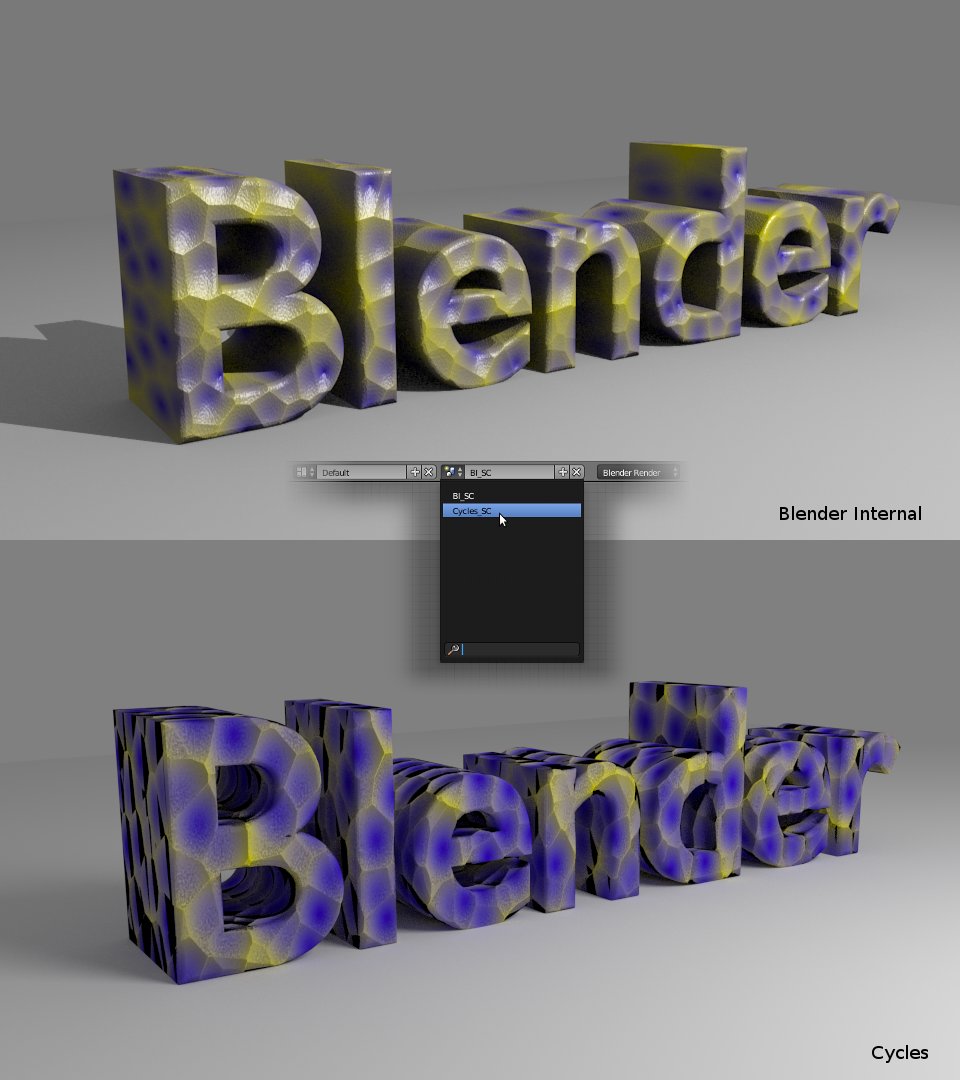
Download the Blender file here: procedural_BIvsCycles02.blend (599 KB)
Anyway - I’ve had an attempt at converting the BI texture including spec and bump over to Cycles. It’s kind of there but nowhere near refined as yet.
Perhaps texture gurus can correct my workflow?
Lancer
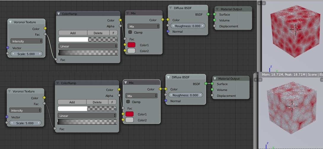
here is a possible approach to your model and shader network:
Upfront you will never get a 1:1 match between BI and Cycles.
The specular highlight is fake and cannot be done the same way in Cycles.
So I needed to do some hacks here to get it similar to BI.
First the color should be mixed in just a color mixer and not with two glossy shaders.
It is faster that way when using one shader.
The ramp node for the Voronoi texture defines how much bewteen blue and yellow is being blended
and at what point.
Second the glossy shader that adds the reflection highlight of the light source is being mixed
onto the object via an inverse fresnel function to make perpendicular faces reflective - that’s how
the fake specular works.
Third the bump maps are mixed together and fed then at once into the displacement node.
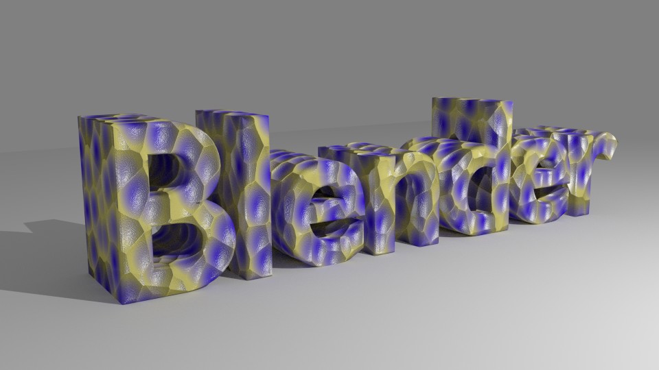
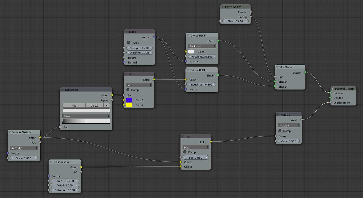
Blendfile: http://cl.ly/3N0s3c0r0Z1D
I hope this helps
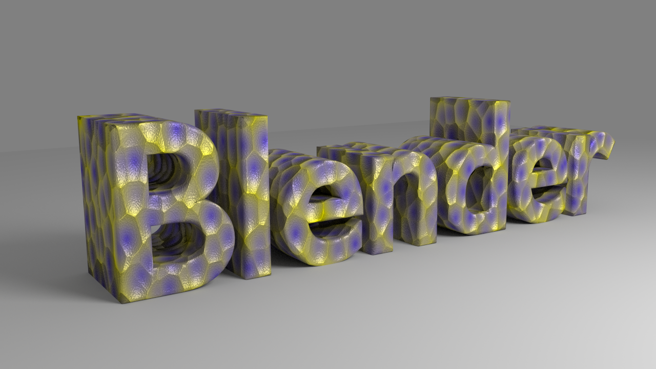
With the big difference that your fake specular imitation fits the BI better!
Awesome work on those, and thanks. I’ll be studying these in more detail today for sure 
Question: a number of your nodes are going yellow <=> grey (the plugs). I thought the workflow involved trying to match like plug colours… is grey wildcard?
@ Lancer:
Grey sockets are single value sockets. yellow sockets are color sockets and blue ones are vector sockets.
Basicly colors and vectors are storing 3 values (for colors: red, green, blue and for vectors: x y and z)
If you take for example a value node with a value of “0.5” and plug it into a color its interpreted as 50 % grey.
So its simply taking the value for all color channels and the same would happen if you plug it into a vector node.
Edit: Also if you put a color value into a value socket you get the lightness (the same thing you get when you put the color into the color to black and white node)
@Lancer: Funny… You made me realize that I systematically plugged grey outputs into yellow sockets and yellow output into grey sockets.
Any way, after all that GrivingSights said, I’d say that, yes, grey outputs are a kind of wildcards… and the yellow sockets are the one-size-fit-all holes of the node tree. It’s just faster to use the Color nodes than to re-build the same thing with Math nodes for single values… which will simply be considered as greyscale colors by Blender. (The same single value for the 3 components.)
There’s a tiny leak of CPU power along the pipes because of the conversions but it’s nothing compared to what would happen with the forest of nodes needed to replace a single Color node. 
@Cekuhnen: You made an error. Black = 0 and White = 1 but you inverted the values for the Alpha channel. If you didn’t there would be no difference in between using the color output or the alpha one. (Most of the time, I use the alpha channel of the color ramp to avoid the useless conversion.)
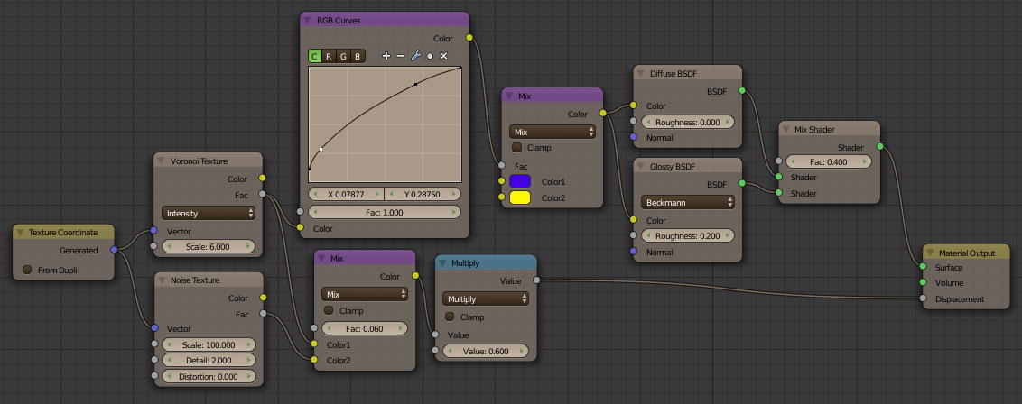
I’ve been looking into people’s solutions for converting the textures. Very interesting.
Cekuhnen, how does your fake spec (with the Layer Weight / Bump / GlossyBSDF) acutally work? The Bump has no input and I’m not sure how Layer weight works… does it make the fake white spec show only when surface normals are pointing towards the viewer?
Kaluura
Yellow is for RGB
Gray is gray scale and transparency - ever noticed that the color ramp node has a gray alpha output?
That value can be used with screen function !
I wouldn’t say grey sockets support grey scale images but numeric values.
But it supports one numeric value per pixel, that can be visualized as a grey scale image.
Also transparent pixels work the same way: 0 means transparent, 1 opaque and so on.
And obviously yellow sockets also support single rgb values…
I’ve been looking at Kaluura’s solution to the texture conversion. The only part I don’t get is the Generated “Texture Coordinate” texture. For me, adding this node appears to have no effect and the texture coordinates can be put directly into the X, Y, Z scale properties of the Mapping area below the texture tab.
…can someone please show me what I’m missing there?
mapping normally works only in X and Y
to use Z you need to be in Box mode !
happy cycles
@Lancer: You’re right. The generated texture coordinates are useless. It seems that they are the default coordinates used by Cycles when none are provided.
I’m a Cycles guy, I do everything in the node tree. In general, I work with Object coordinates for such “volumetric” procedural textures… but somebody messed with the texture scale in the Texture tab. (I just didn’t think about looking in there.) Since there’s no real UV map, I used Generated. I don’t like to use textures without explicit coordinates.
about mapping node
any ideas if we will ever be able to access the values inside in node editor
or only with drivers ?
thanks
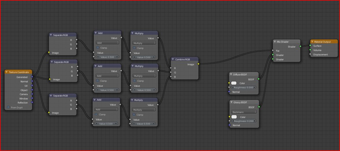
It actually is possible to make a node setup to allow the manipulation of the location and scaling coordinates using the following steps…
1). string the output of the texture coordinate node into a ‘separate RGB’ node.
2). string all three outputs through a ‘math’ node set to add and then another math nodes nodes set to multiply, if you do it right, you’ll have a pair of math nodes each for the R, G, and B, channels.
3). Use the ‘combine RGB’ node to combine the values together and use the manipulated information as the texture coordinates.
Basically, how this allows for texture-based manipulation is that now you’ll be able to change the coordinates by stringing texture information into the second output of any of the math nodes.
interesting
can you show nodes set up
i’ll test that and see how this works
and is it valid for all 3 axis for locations rotations and scales ?
also use with Box mode
how do you control the loc rot scale ?
vaguely remember abour RGB color being the locations only
but what about rot and scale ?
thanks
Okay, first off, it’s kind of a waste to use three copies of the separate RGB node and use just one of the outputs, you can easily condense that part down to where you’re using all three outputs on one node rather than what’s in the image.
Second, you don’t actually have any texture right now in the material, to manipulate the texture, you would connect the output of the combine RGB node into the vector input of the texture node (which you then proceed to connect the color or fac. output into the color input of the material.)
I know what you’re thinking, yes it is true that it means plugging a yellow socket into a purple one, but the reason it works is because the vector data is essentially a special kind of RGB data used by the engine to do things like map textures and define normals. Therefore you have the ability to alter this data to get certain effects. (one of the ways being what you did in splitting the vector data into individual color masks, manipulating them, and then combining them back into RGB data and thus creating new vector data).