There is one light source which is close to an E illuminant, then the front red one is like a red laser, only containing a range of about 10nm. The objects are using the sRGB>spectrum node using pure green and pure red as inputs. I expected the red to be a little more red, but maybe it is correct considering the ‘laser’ (in terms of colour, not direction) red light would have to be substantially more saturated. The reflectance curves are the spectral_r and spectral_g from your code above.
Aha I thought you meant you had a red and a green light shining ON those objects :-P.
Oh I think I realized another thing that is going to be wacky. Using lasers/ pure spectral wavelengths, or really any lightsource that has a chromaticity outside the sRGB gamut is going to give you results (likely) outside the sRGB gamut and be screwy without gamut mapping. So instead of a red laser maybe just use the actual spectral_r curve as your red light. For your white light you should even be able to just combine the 3 spectral primaries into one SPD. So yeah anytime you define a custom colored light you’ll want to convert it the same way you’re getting the object reflectance curves. It seems really weird that a reflectance curve is the same thing as a emission curve depending on the context 
If you haven’t noticed, if you add up the three curves the sums do not replicate the D65 SPD, so the upsampling method is probably a bit screwy still. But so is generating reflectance curves from thin air, I suppose 
Oh, just in case, the spectral wavelengths that I’m using are from 380-730nm. I had a thought that maybe your wavelength–>xyY code was starting at a different wavelength and misaligned.
Nope, I assumed that’s what you’d be using, given the number of entries in it. Until I do more thorough testing I really can’t say if the colour shift is my fault or if it is just a result of what I’m rendering.
1 Like
Actually what I meant is, they don’t sum up to equal exactly 1.0. BUT, it is pretty close and I haven’t noticed any weird aberrations in all my gradient testing. You know, I think we could modify that spreadsheet to find 3 curves instead of just one, and add another constraint so that the sum of the 3 curves == 1.0. . .
Here’s the sums right now:
1.046054867
1.046051509
1.046074529
1.046106173
1.046224892
1.046676986
1.048062654
1.052093511
1.062662512
0.959976384
0.743673935
0.700209676
1.01941267
1.125711085
1.080420036
1.055923147
1.043346709
1.038613704
1.041557714
1.057549535
0.753239277
0.621617663
1.102341236
1.135491882
1.10522924
1.090023695
1.081981308
1.077802471
1.075641805
1.074562248
1.074050986
1.07381911
1.073705255
1.07364948
1.073620099
1.073609648
1 Like
Something was definitely not quite right. The whole process seemed to be there but the colours were still quite a ways off when using CIE RGB, but are much closer with ProPhoto RGB which is an entirely unrelated (as far as I’m aware) colour profile. Turns out I was converting to Wide Gamut RGB. I re-wrote my code and I’m using different transforms now. While it still isn’t perfect, it is much closer>
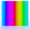
Here’s an image going through the following transformation sRGB image data => sRGB>Spectrum node => Spectral render to 36 images => wavelength>xyY converter => xyY to XYZ => XYZ to ProPhoto.
I’m still lost as to how the white-point is managed, but I believe it has been taken care of in the XYZ to ProPhoto transformation which came from this great resource: http://www.brucelindbloom.com/index.html?Eqn_RGB_XYZ_Matrix.html#WSMatrices
Reference Image rendered with blender controlling the colours (full saturation hue diffuse plane in white light):

Image going through the process, without any manual correction (E illuminant, using the RGB to spectrum node group and my colour conversion functions in JS):
My largest concern is with the green and yellow saturation. This is by far the best result I’ve gotten so far, though.
I wonder if simply multiplying each item by the inverse of the sum would be enough to get a smooth output. The two spots where it dips below 0.7 look a bit concerning, but I’m not knowledgeable enough to know what I should worry about and what is normal. Somewhere along the way, something is a little off. So many ways to do it wrong, only one way to do it right!
Well, the thing is the results of that reflectance curve is actually “good”. That is, multiply that by the D65 SPD and you’ll get sRGB 255,255,255 after all the conversions. I think what it means is that for very reflective objects that use a lot of R G and B (like white or other low chroma bright colors), the reflectance curve might have some values >1.0 which would be like. … phosphorescence. But I really doubt it will be noticeable
I don’t think the view in blender will ever “match” the results unless you actually use a D65 illuminant in the scene. Which I think makes sense and is desirable.
You might need to go XYZ -> ACES color space to be able to use any wavelengths. That’s why I was thinking just use sRGB-derived light sources so you can just do XYZ -> sRGB in photoshop and not worry about gamut mapping
Hmm okay. I think I need a more solid fundamental understanding really, but do think I know what you’re saying.
I did create a D65 illuminant, but the result was even further off. It had far too much blue, but without a better understanding, I can’t tell if that’s because of my transformation functions being bad, or my workflow not being correct.
I had a thought: Would I need to be multiplying (or dividing?) the sRGB’s component spectra by D65?
I don’t understand why I would not be able to get spectra which represent sRGB and then be capable of producing results (which might or might not lie outside of sRGB gamut) with accurate colour reproduction. I feel if the spectra I generate are correct, and my processing is correct, I should be able to take an image, split it up into the spectrum, illuminate it with a D65 illuminant (which I have created) then process those files back into something that looks very close to the original.
How that spectrum interacts with illuminants other than D65 is obviously going to not quite match reality, that is to be expected. Currently things are a bit too far off for me to believe it is just an issue with the precision of the transformations. I think my process must still be wrong somewhere.
Well don’t get discouraged, I’m pretty confused too.
I’ve been kinda of thinking/wondering along similar lines but I don’t think so. So, if we have an object that is sRGB red, so it has a reflectance curve exactly matching the spectral_r, right? So if we just look at, say, 590nm wavelength, this object should reflect 0.27954, so 28% of the D65 illuminant’s 590nm wavelength. If we put a new illuminant on this object, say, E, it’s still going to reflect 28% of that particular wavelength, right? SO, I think we’re ok. yes, it will look different under E than it did under D65, but that’s exactly what we want. . . and I think we could say that DOES (mostly) match reality.
So if we have an “yellow” object, we do the same thing but the reflectance curve is going to be spectral_g + spectral_r. Are you summing these, or are you rendering each channel independently? I guess either should work equivalently. That is, for a yellow object you could render a green object and then a red object and then sum them.
Can you share a sample of the hue spread with the D65 illuminant? I’m curious what you mean by too blue
i have done a quick read in the interesting thread,and just want to post this link of colorpy.this has helped me and others in the research for a thinfilm shader build.
as a example.
with colorpy, you can calculate a thinfilm with D65 lighting, from air to water.and you get the calculated spectrum.
here the github page,maybe its helpfull for you.you can see all the code for calculations.
here the page from the dev.its very informative.
http://www.markkness.net/colorpy/ColorPy.html
2 Likes

ProPhoto D65 light source
I think you’re right. I’m guessing my handling of the white point might just be off once I get the spectral data. The spectral data is rendered with absolute intensity of each wavelength (therefore different spectral profiles on lights will cause the result to look different), so I guess you could say it is E illuminant. At no point am I explicitly changing that, and I can’t glean enough information from the numbers I’ve got for the various transformations to know if they’re doing any sort of adaptation either.
@pixelgrip thanks for the link! I’ll definitely have to take a look at that, it might have some hints into how my process is off.
How are you doing XYZ → ProPhoto? I’m thinking since ProPhoto has a white point of D50, which is warmer than D65. . . if you don’t account for that with a chromatic adaptation transform (bradford) it will cast a blue tint on the image.
I’m not sure I follow. The E illuminant is a totally flat power distribution curve but is otherwise the same concept as any other illuminant or light source. So I’m thinking the reason why illuminant E gives you the best result is maybe because the CCT of E is 5455K, which is much closer to D50 than D65 is to D50.
Another aside. . . the whole reason I’m using the spectral primaries and doing the upsampling is for speed, so I can real-time paint. For a rendering, you might want to actually just do the Meng method for every color and just have another cup of coffee. But maybe worry about that once you get everything working.
http://www.brucelindbloom.com/index.html?Eqn_RGB_XYZ_Matrix.html#WSMatrices
On this page, I am using the second matrix in the ProPhoto RGB row. It does mention just above the table something regarding chromatic adaptation, but I gathered that to mean that the matrix does the adaptation while transforming from XYZ to ProPhoto. If that isn’t the case, I will need to figure out how to do the chromatic adaptation transformation.
I think you’re right regarding my success with E illuminant. If I make a D50 illuminant and the result comes out grey, I know that’s the issue.
I’m not sure how familiar you are with node based shaders, and I’m not particularly familiar with Meng, but I feel this is somewhere between rather difficult and impossible to do. I might have a look at it once I know my technique is right.
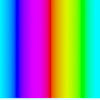

EDIT: New profile next to ground truth.
This is how it looks with a new profile, ProPhoto primaries with a D65 white point, and illuminating the scene with D65 light. This is acceptably close to the ground truth for me to accept that the process is now sound, even if there are some slight variations in the numbers.
1 Like
Awesome!! Yeah Bruce says above that table
"Note that these matrices are given relative to their own reference whites. "
So that would be D50. Fantastic, can’t wait to see a whole scene rendered. Oh, I’m not familiar with the node workflow but yeah the Meng2015 reflectance recovery would pretty much need python to do easily.
Now I just need ideas for what to render! What phenomenon are worth including, etc. The math involved in something like thin film interference isn’t trivial but can be done with this workflow.
My interest was primarily in using different illuminant spectra and seeing what sort of things I can get to happen. The process is pretty simple now so I could even attempt a more ‘normal’ scene and let spectral rendering play a secondary role.
Maybe I could look at structural interference such as what is present in butterfly wings. I am fascinated how it works.