Feedback / Development: Filmic, Baby Step to a V2?

I promise you it is not. Think about where a middle grey ends up, and how much you are over sampling a 3D LUT.

The range is not simply photographic stops. The value is a basic log2, scaled by middle grey. So to properly derive the range, the middle grey scale needs to be accounted for.

Anyways, the chain is pretty basic. The compression assumes all values incoming are the specific log2 range being handed in, and simply transforms appropriately for output.

Then in the stanza, the input is a log2 allocation transform, and then off to the 3D LUT, and done!

I think the problem is that the power(2, col) @kram10321 tried as the inverse of the lg2 allocation transform didn’t actually inverse it, a simple log2(col) will be countered by power(2, col), but log2(col) is actually different from OCIO’s lg2 allocation transform:

@troy_s What kind of operation in python can we inverse the lg2 allocation transform so the math can be applied to Linear state XYZ?

Nevermind, I found it!

                col = colour.log_decoding(col, function='Log2', min_exposure=-10, max_exposure=15, middle_grey=0.18)

This inverses the lg2 allocation transform perfectly.

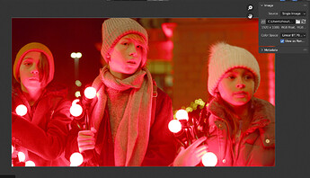
Result:

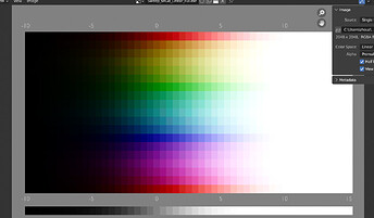
One problem though, the posterization issue pops up again, it’s not obvious in the above screenshot, but when you slide the exposure slider up and down you can see it very clearly in motion.

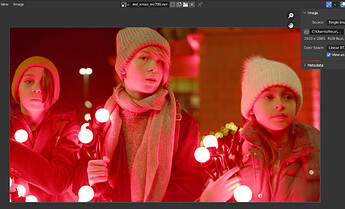
The Red Xmax has more obvious issue:

The thing is, the interpolation method is still best but now it doesn’t seem to be any different than linear, I don’t understand.

@kram10321 How do you change the cube resolution in python code?

1 Like

Glad you figured it out! Was about to try the same thing

change line 52 like so:

LUT = colour.LUT3D(name='Spherical Saturation Compression', size=33)

(33 is the default, but you can pick whatever you like)

I think you want min exposure and max exposure to be the magical 12.473931188 again though?
Not sure…

Oh and if you change the function on one side, the other side probably also needs to change

1 Like

-12.473931188 is the log2 value, convert to exposure value is -10
and exposure value of 15 will be log2 value of 12.526068812

Learnt about it in Troy’s post in another thread:

I also updated the line in the config to use the two log2 values accordingly.

The current way to do it is, in config, enocde the log, then in the LUT, decode the log, so no need to re-encode it. That’s what Troy meant.

ah so it’s supposed to be

            col = colour.log_decoding(col, function='Log2', min_exposure=-10, max_exposure=15, middle_grey=0.18)
            col = transform(col, f1=f1, fi=fi)

rather than

            col = colour.log_decoding(col, function='Log2', min_exposure=-10, max_exposure=15, middle_grey=0.18)
            col = transform(col, f1=f1, fi=fi)
            col = colour.log_encoding(col, function='Log2', min_exposure=-10, max_exposure=15, middle_grey=0.18)

?

and I see, makes sense. That’s what @troy_s meant by

The full script as it currently stands, for future reference:

import colour
import numpy as np


def subtract_mean(col):
    mean = np.mean(col)
    return col - mean, mean


def add_mean(col, mean):
    return col + mean


def cart_to_sph(col):
    r = np.linalg.norm(col)
    phi = np.arctan2(col[1], col[0])
    rho = np.hypot(col[0], col[1])
    theta = np.arctan2(rho, col[2])
    return np.array([r, phi, theta])


def sph_to_cart(col):
    r = col[0]
    phic = np.cos(col[1])
    phis = np.sin(col[1])
    thetac = np.cos(col[2])
    thetas = np.sin(col[2])
    x = r * phic * thetas
    y = r * phis * thetas
    z = r * thetac
    return np.array([x, y, z])


def compress(val, f1, fi):
    fiinv = 1 - fi
    return val * fi/(1 - fiinv * np.power(((f1*fiinv)/(f1-fi)), -val))


def transform(col, f1, fi):
    col, mean = subtract_mean(col)
    col = cart_to_sph(col)
    col[0] = compress(col[0], f1=f1, fi=fi)
    col = sph_to_cart(col)
    return add_mean(col, mean)


def main():
    # resolution of the 3DLUT
    LUT_res = 33
    # curve shape parameters
    f1 = 0.9  # how much saturation compression there is at a spherical saturation of 1
    fi = 0.8  # how much saturation compression there is at a spherical saturation of infinity

    LUT = colour.LUT3D(name=f'Spherical Saturation Compression {f1=} {fi=}', size=LUT_res)

    min_lg2 = colour.models.log_decoding_Log2(-12.473931188, min_exposure=-10, max_exposure=15, middle_grey=0.18)
    max_lg2 = colour.models.log_decoding_Log2(12.473931188, min_exposure=-10, max_exposure=15, middle_grey=0.18)

    LUT.domain = ([[min_lg2, min_lg2, min_lg2], [max_lg2, max_lg2, max_lg2]])
    LUT.comments = [f'Spherically compress saturation by a gentle curve. Resolution {LUT_res}',
                    f'Very high saturation values are reduced by {((1-fi)*100):.1f}%.',
                    f'At a spherical saturation of 1.0, the compression is {((1-f1)*100):.1f}%.']

    x, y, z, _ = LUT.table.shape
    for i in range(x):
        for j in range(y):
            for k in range(z):
                col = np.array(LUT.table[i][j][k], dtype=np.longdouble)
                col = 2 * 12.473931188 * col - 12.473931188
                col = colour.models.log_decoding_Log2(col, min_exposure=-10, max_exposure=15, middle_grey=0.18)
                col = transform(col, f1=f1, fi=fi)
                # encoding not necessary
                # col = colour.models.log_encoding_log2(col, min_exposure=-10, max_exposure=15, middle_grey=0.18)
                LUT.table[i][j][k] = np.array(col, dtype=LUT.table.dtype)

    colour.write_LUT(LUT, f"Spherical_Saturation_Compression_{(f1*100):.1f}_{(fi*100):.1f}_r{LUT_res}.cube")
    print(LUT.table)
    print(LUT)


if __name__ == '__main__':
    try:
        main()
    except KeyboardInterrupt:
        pass

Or wait, do I not even need

col = 2 * 12.473931188 * col - 12.473931188

? Does the log_decoding already take care of that part?
As far as I can tell that part is still needed

1 Like

I have decided to use resolution of 70. Seems enough, no more posterization.

The view on its own works perfectly now.

But the contrast looks are still not working, I don’t understand

EDIT: Uh, I know now, the LUT is non-reversible. I have been doing it in AgX Log hoping the contrast looks can benefit from it. It seems I have to do it in AgX Base then, and the contrast looks will not benefit from it.

1 Like

Just in case anybody wants to generate their own, I just made the script a bit simpler to use:

Just modify the three parameters at the top of main() as you like.
It will automatically generate a .cube 3DLUT with appropriate file name and descriptions.

Is there a simple way to figure out the exact lg2 value of min and max exposure? Then I could easily add ways to make this robust to different choices of middle greys, and exposure ranges. Mostly for future-proofing. I don’t think fiddling with that right now is necessary

Oh perhaps a bit late but I was looking for this one:

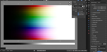
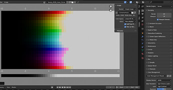
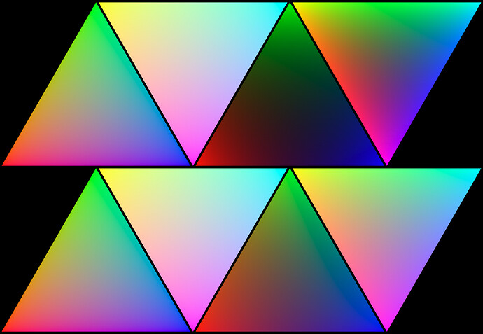
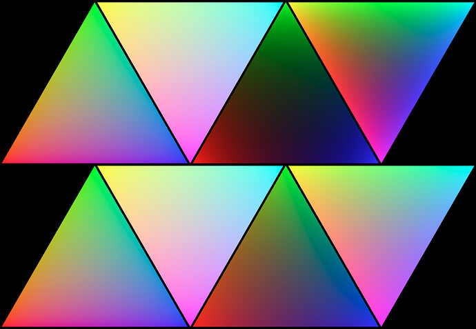
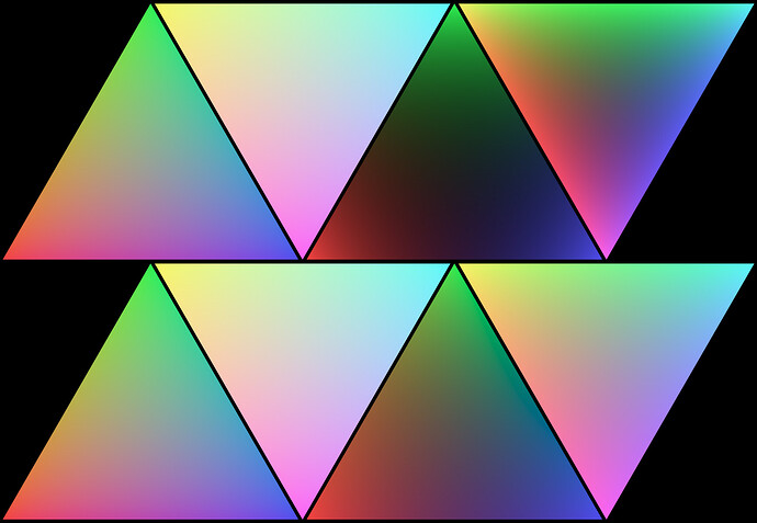
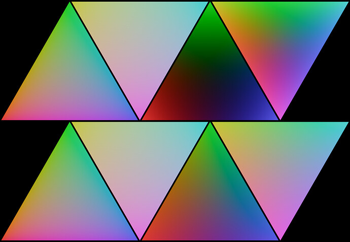
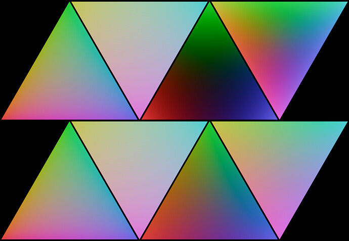
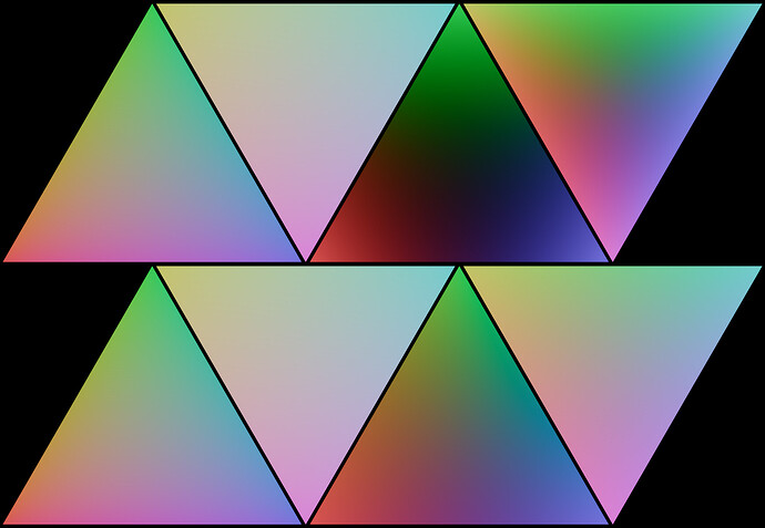
In this test I’m mixing either RGB (triangles pointing up) or CMY (pointing down) colors either in RGB space (top) or spectrally (bottom) either additively like light (left) or multiplicatively like paint (right)

It should only display colors that are within sRGB, however in the multiplicative spectral interpolation version (bottom right) I’m mixing the spectra that we determined to correspond to the sRGB primaries in nontrivial ways, so you can’t get those exact spectra by directly selecting the corresponding colors.

Anyway, long story short, this should show pretty well how specifically sRGB colors are getting mangled. Because of this, I also provide a Display Native starting point.

Display Native

Display Native, saturation curve

Display Native, saturation multiplier

AgX Chroma Laden

AgX Chroma Laden, saturation curve

AgX Chroma Laden, saturation multiplier

Don’t worry about the specific domain of XYZ in this case, consider how to invert the encoding. I covered the basics of the AllocationTransform here.

Important note: The forward encoding and the inversion must match 1:1 precisely, otherwise all calculations will be wrong. It is important to test the encoding through decoding process.

Correct. Remember, the encoding is a compression scheme to assert maximal density coming into the processing algorithms. The processing algorithms can output exactly what they want, which is why the output can be considered “complete” at that point, if required.

The important part is to appreciate why the shaper side is required. If we have a domain of 0.0 to 1.0 but the importance is non-uniform, such as “middle” being 0.18, we can see a discrepancy. If our “important range 50%” goes from 0% of the encoding to 18%. That’s 18% that we are “stretching” to 50% importance. That means that in terms of a 3D LUT, which we can consider from 0% to 100%, we’d be leaning heavily into the sampling of the 0% to 18% range of the 3D LUT, and wasting many of the LUT values from 18% to 100%!

As before, OpenColorIO has some brain wormed design that simply doesn’t work. Don’t try to overfit things that are working algorithmically into the design of OpenColorIO. Just because it might seem “tidy”, doesn’t mean it works. Make it work, and hack around the clunky OpenColorIO brain wormed nonsense parts. That likely means jettisoning looks, but you’ll have to arrive at that on your own. I’ve tried to make their architecture work. It can’t. It’s brain wormed.

Yes. Remember in OpenColorIO, the log2 is a pure log2. That means that any scaling for “middle grey” needs to be calculated prior as per the link I included and that is referenced above.

Nice work folks. Keep hammering!

2 Likes

Assuming what we did here is fine, what’s next?
I remember you mentioned doing the spherical saturation change backwards on a later point. I’m assuming that would be instead of the simple saturation boost of Chroma Ladden right now? Or how did you mean that?

I figured out that in order to make the LUT reversible, re-encode the log before the end of the LUT is actually needed (then re-decode the log in config afterwards), and that solves the posterization problem, now I can use 33 resolution without any posterization. Will test more.

1 Like

Now that I roughly know how LUT creation works, I can be of much greater help for this project. You already did a lot of the heavy lifting, but if there is any specific transform you or @troy_s have in mind, I can probably whip it up.

Although now that you saw what it takes as well, maybe you can also figure it out on your own. Maybe we can soon reach a point that we might consider to be “done”. Then we can ask to push it with Blender Master

btw, one good reason to be conservative with LUT res is Blender build size. Luckily LUTs are highly compressible, so in the zip they won’t take up a whole lot of room, but the uncompressed form can potentially be quite massive. - So I’m glad it works fine with a resolution of 33.

It’s a good question!

If you’ve noticed, I’ve tried to be a bit “hands off” as I typically value what other folks can bring to the table, and being too “hands on” is often to the detriment of that.

What I would probably consider is a canned configuration that covers the following display devices, under “average” viewing considerations:

  1. sRGB.
  2. Display P3.
  3. BT.1886
  4. ST.2100.

For each display class:

  1. Display Native. (Inverse EOTF.)
  2. Base Inset. (Maximal granularity for folks rolling their own twists in some other grading tool.)
  3. Chroma Laden (Gentle expansion that approximates a Goldilocks balance between chroma and posterization.)

Plus an appropriately labelled set of data encodings, and backwards compatibility via aliases etc.

Keep it streamlined to only the three view transforms, for clarity. Ditch looks, because it makes the configuration absolute nightmare fuel. Potentially consider some open domain looks as options, but frankly, it’s complex enough for testing purposes with the three above.

The spherical compressor can also be plausibly used for chromaticity purity expansion. It would be worth testing this, as the default I included in AgX uses the basic CDL saturation transform, which has an implicit hard coded BT.709 assumption.

I suspect a spherical expansion is worth trying, as it might allow for more pure chromaticity expansion, while perhaps stalling posterization? Worth a test!

I would strongly lean to keeping the configuration as absolutely streamlined as can be, while providing enough baseline testing displays to get valuable feedback from folks with the QD OLEDs and the ability / know-how to test. Other community members can be hugely valuable here.

Don’t jump ahead.

The key here is to get to a reasonable test bed for testing. Folks need to grind this out with spectral cycles and ideally, camera footage / compositing, and make sure the intention of the image is held up.

This is where the spherical compressor / expander can be harnessed. Assuming the working space is set to P3, the compression can be used post image formation to avoid posterization on BT.709 and sRGB mediums, while also used to gently expand upward for one potential creative intent to wider footprint mediums.

The basic test should be appearance matching between commodity Display P3 mediums and sRGB / BT.709. Things to watch for:

  • Consistency of appearance under average viewing condition surrounds. (Not “dark” nor “dim”, which would require separate configurations or transforms.)
  • Consistency of general “chroma” sensations between Display P3 and sRGB / BT.709.
  • Consistency of “brightness expansion” when rendered for EDR on YouTube. It would be wise to establish the 1000 nit maximal achromatic as the baseline test range, given no other displays exist out in the wild for the majority of consumption.

There’s a huge discussion here about “creative authorial intent” with respect to brightness and chroma expansion, but that’s something to look at down the line. Getting the clay roughed into shape for general drafting of community members to test, is wise.

Once the configuration is stable enough, it is worth trying to draft some key image authors for testing and feedback. While random opinions are random, focused individuals who are making shorts, or engaged in making smaller studio work etc. will have tremendously valuable feedback.

Most importantly, use consistent terminology that is forward looking. Don’t yield to dumb ideas and the hodge podge mess that currently exists. Structure it around the image authors who are sought out.

The authors are the most important group.

I absolutely have noticed this, and it’s very fair, but I’m still far from an expert in any of this, so any pointers are appreciated

Ok that sounds like you’re basically suggesting finalizing this. Variations sounds like the very last step to me.
The Aliases stuff is definitely the final touch. Like, that’s usability stuff, which is important, but should be relatively straight forward.

Is the Base Inset what currently is AgX?

I wish I had access to screens of that caliber.

It’s tricky to reach new testers if it’s hardly available… Maybe it could be marked as “Experimental” / “Beta” as a call for testing, rather than becoming the default right away (as currently is the case with Filmic)? Although at that point it’s gonna be a discussion with devs too, I’d imagine.


OK so situationally use the compressor, or its inverse, after the AgX transform, but once again in XYZ, right?

Ok that sounds like now we’re getting into the real technical stuff. How to even appropriately test all that? I’d guess you’d actually need various properly color configured screens set up correctly in those various modes to really test this? I don’t really have the necessary tools for that. Hopefully somebody else does…


I guess as of right now the authors would be those active in this thread, i.e. us. I’m not sure where you’d imagine we’d get more people into this group. I mean we can mention AgX elsewhere or what not, but I’m not convinced that’ll actually get people in for this.
The easiest way I see would be to include it with various builds (alongside Filmic) so people at least have a chance of discovering it…
I mean I appreciate the advice there, and I get the truth of it, but it feels like a thing that’s difficult to actually control.

Aliases are more or less in place already, basically the previous Linear colorspace will be interpreted as Linear BT.709 I-D65, Raw and Non-Color will be Generic Data etc.

It’s the AgX Base colorspace, used by the AgX view.

I think we need somebody with both calibrated Display P3 and sRGB monitors to test this…

For HDR and EDR stuff we need people with those monitors as well.

And not to forget a new false color mode,since the old was not correct with displaying exact the 0.18% grey.

I think would be a nice addition.

100%.

The “clay” of the thing we bake into a formed image will have a specific domain.

Assuming an image formation doesn’t result in values that escape the working space tristimulus, then a P3 working space to Display P3 formation might require little to no chromaticity compression.

On the other hand, when we try to relay that formed image as we see it in a Display P3 display medium to a BT.1886 display medium, we have to be careful that the values that cannot be expressed don’t distort and / or posterize too much. If they do, the formed image may then be different enough from the Reference Image as to be deemed a different image.

Part of the onus of a management chain is to have the author reliably lean into the chain so as to know her imagery will match her authorial intentions, and these sorts of details will accumulate.

There’s a limit as to what a single individual can do, but there is real strength in a robust community as there is here. There’s an army of open minded and skilled image authors here, many of whom are able to test across a variety of mediums.

Part of that deal though is to make as much effort to make the testing less labour for them, so a streamlined configuration, and streamlined configuration generator are paramount.

It’s all labour, so treating it as such can help to cultivate a good testing group!

As someone with more than a healthy bit of exposure to quite a few colour science research tidbits, I wouldn’t let too many folks scare you away from simply evaluating and asking for specific evaluations. Every single Colour Appearance Model I have seen varies from “somewhat wonky” to “complete bed shit”. Plenty of the standards and protocols out there are equally ass.

So keeping a reasoned eye on the variables and soliciting general feedback from quality image authors is extremely reasonable.

Of course there are a million nuances, but within that, if the system aids in the crafting of kick ass imagery and delivery, it is by definition successful.

The trick is to help get the image authors excited and interested in the work.

Find folks who create amazing work and reach out to them with a clear test plan and feedback on specific facets. That’s how the original Filmic design worked. I suspect it will work again.

Getting it into ship-shape for use with Spectral Cycles is another solid advancement, and @smilebags is a great resource here.

Don’t forget that every person with an Apple MacBook immediately gets a very good quality Display P3 with it, and every person with a newer model 12.9” iPad Pro has a very solid quality 1000 nit testing machine.

Surely there are some authors here who have the Alienware QD OLED as well, which opens up more testing if the mode can be induced properly etc.

I agree. I would think that there’s a number of “flourishes” that would be great as options, but it should be tempered against designing something streamlined for audience testing at this point.

All in all, it makes good sense to parallel all of this work with some before and after chromaticity diagrams to showcase the influence of the spherical compression on the working space colourimetry, and how it is positively or negatively impacting the subsequent image formation.

These sorts of things can all be automated, as well.

Update version 11.7.

  • Change working space to Linear DCI-P3 I-E

  • Add spherical compression.
    Note compared with what I posted before, I also changed the log2 encoding’s lower end value to fix some bugs I found when trying to visualize the xy plot again.

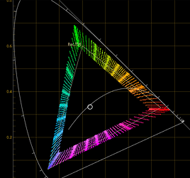
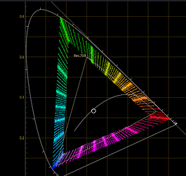
P3 primaries getting compressed:

BT.2020 primaries getting compressed:

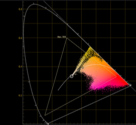
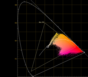
Red Xmas before compression:

Red Xmas after compression:

EDIT: This plot is clipped at the boarder of XYZ, non-clipped version is below at post number 707 (number in URL)

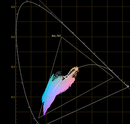
Night Clube before compression:

Night Club after compression:

The compression is fascinating!

Great work on the plotting!

This is clipped to the AP0 condition, which is wrong. The Red XMas image has Red Gamut (no pun intended) primaries, and the Red XMas values carry out well beyond the locus. There should not be a hard wall as there is along the locus edge.

This seems odd. We can see the tristimulus near 575nm move in sharply, but the longer tristimulus positions do not? I would expect a more uniform contraction here?

Something feels off here?