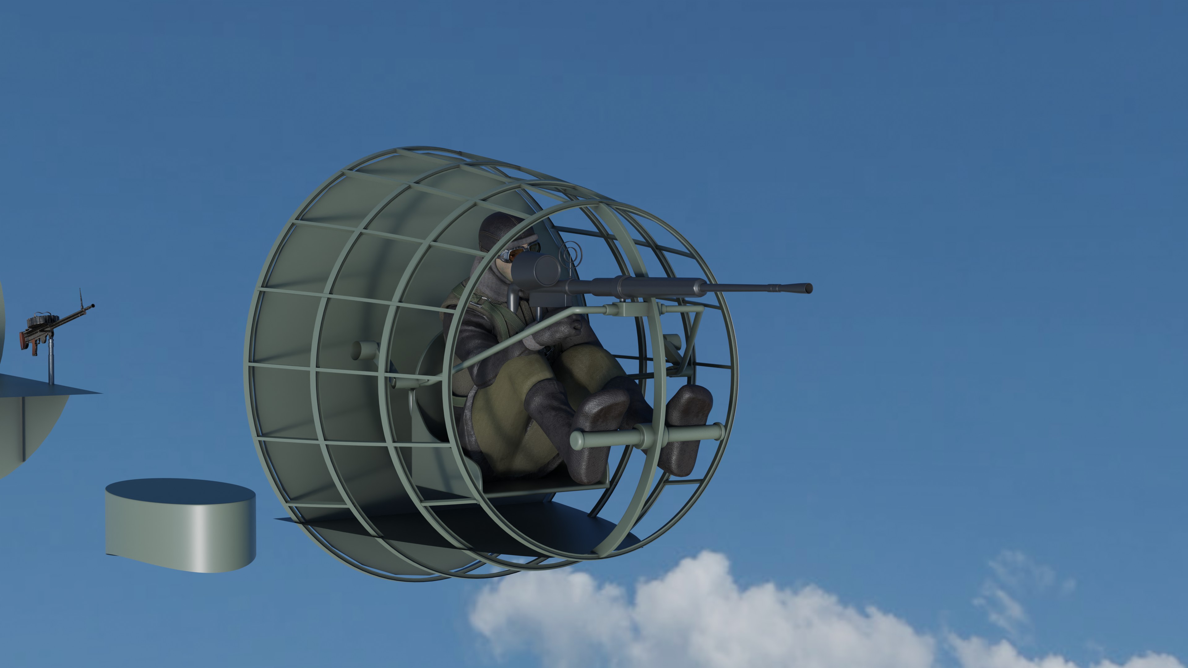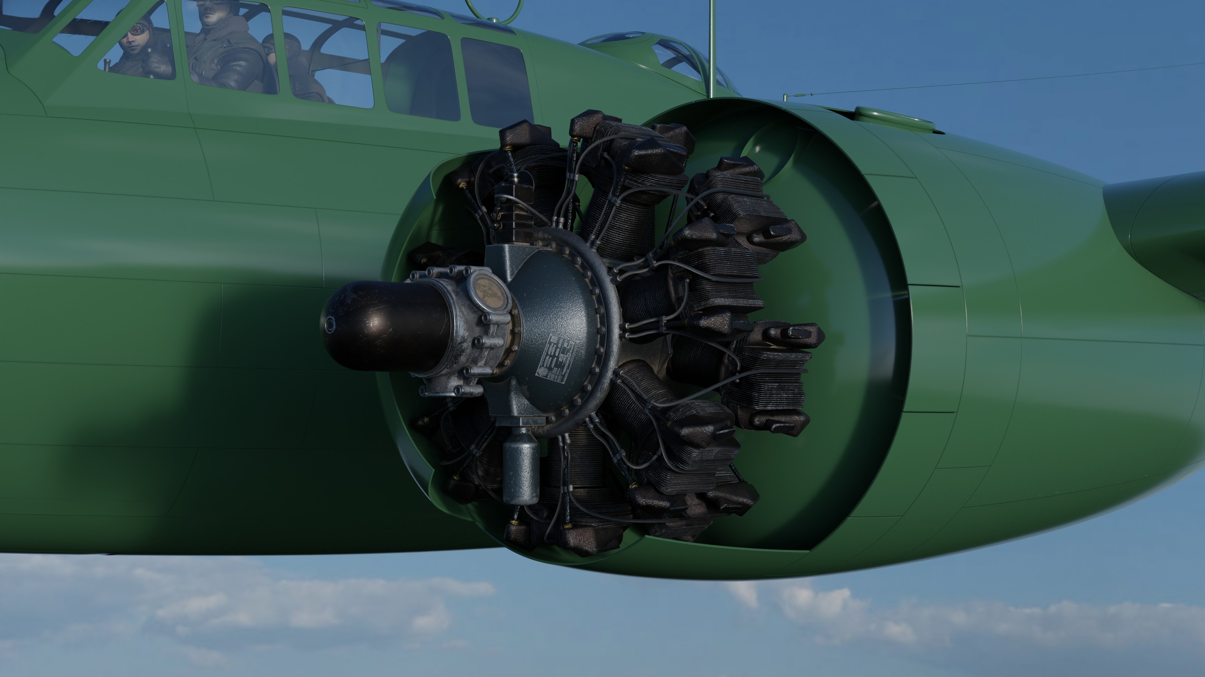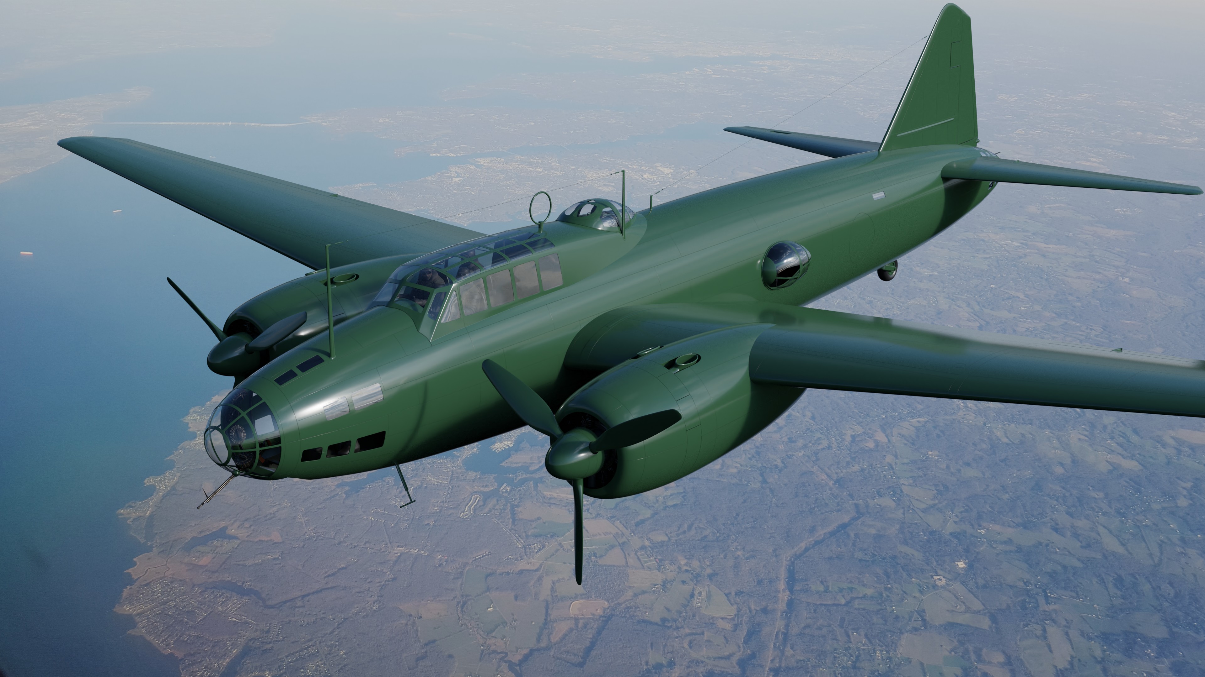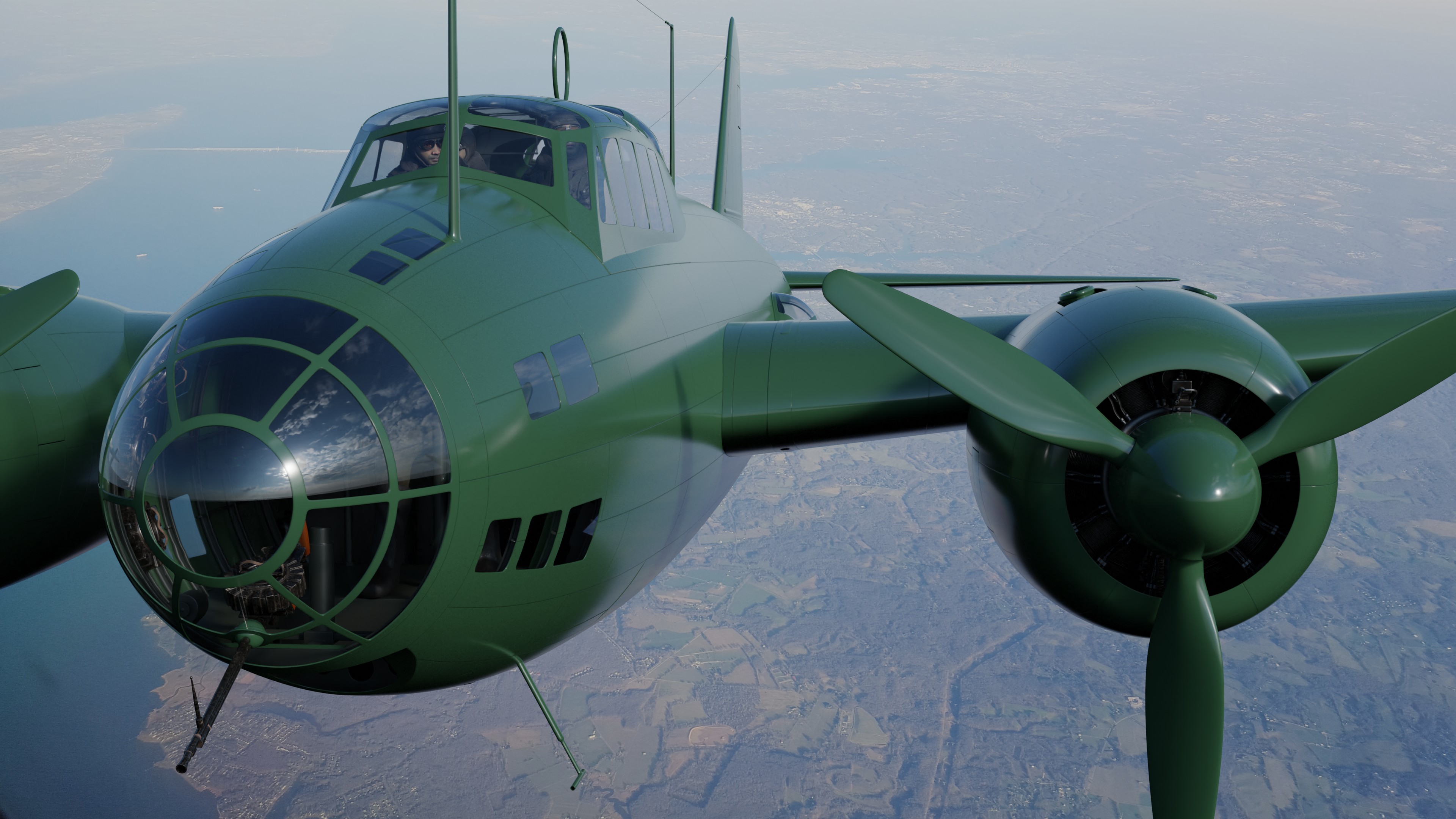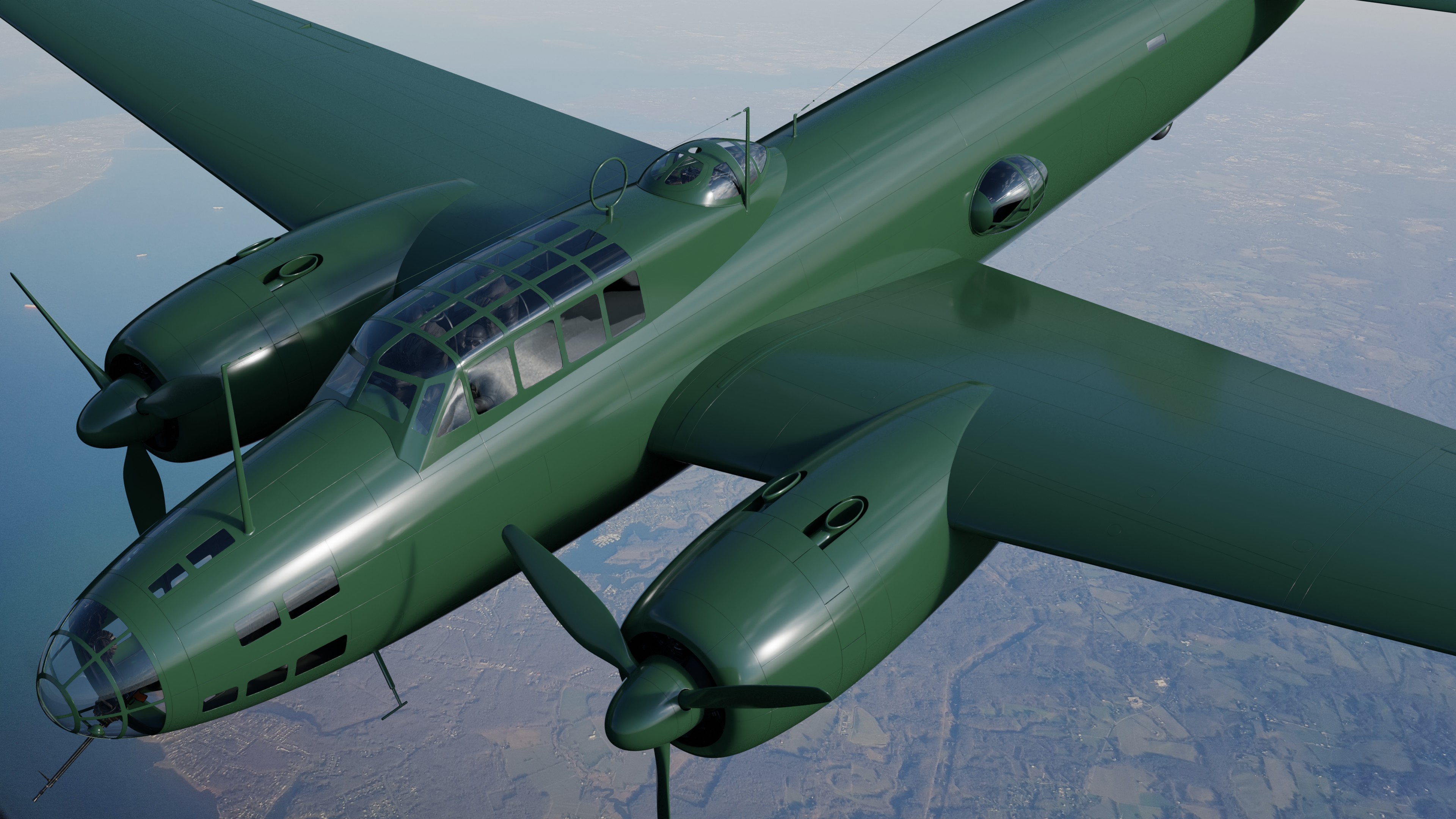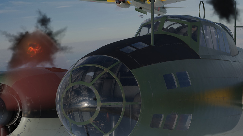
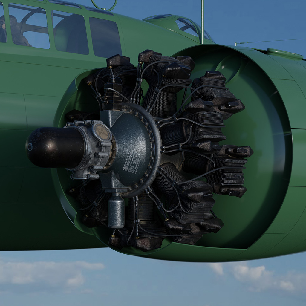
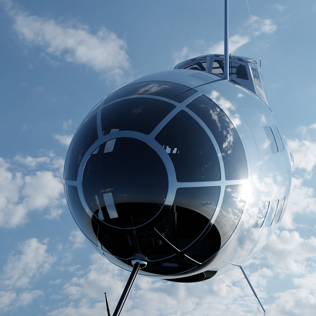

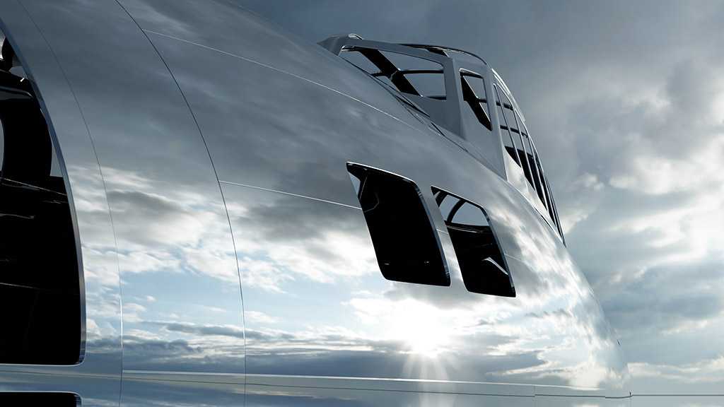
Instead of just posting pictures of my progress on this aircraft, I’ll also be including information about my process for modeling hard surfaces. Basically, the things I wished I had known when I first started using Blender.
The first step is getting good reference materials. Get the best drawings and photographs you can find. Organize them and double check them to make sure they’re accurate. The drawings & reference material are the foundation of the project. If they’re good, the project will progress much more quickly. If they are of poor quality or inaccurate, the project will become a nightmare as you realize parts don’t line up and out of proportion.
I also recommend working in full scale. If the object you are modeling is 20,000 cm long, make sure you scale the image planes to the appropriate size. If you keep all of your projects in full scale, it will be much easier to integrate them together later and re-use common assets (like figures, engines, guns, etc.).
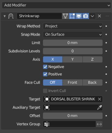
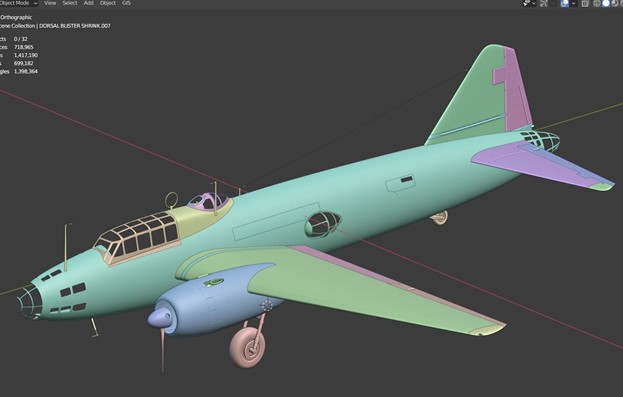
After setting up and scaling the image planes, start building simple low-poly meshes that define the basic shapes of the object. These will become the base mesh that is later used as the target of SHRINKWRAP modifiers.
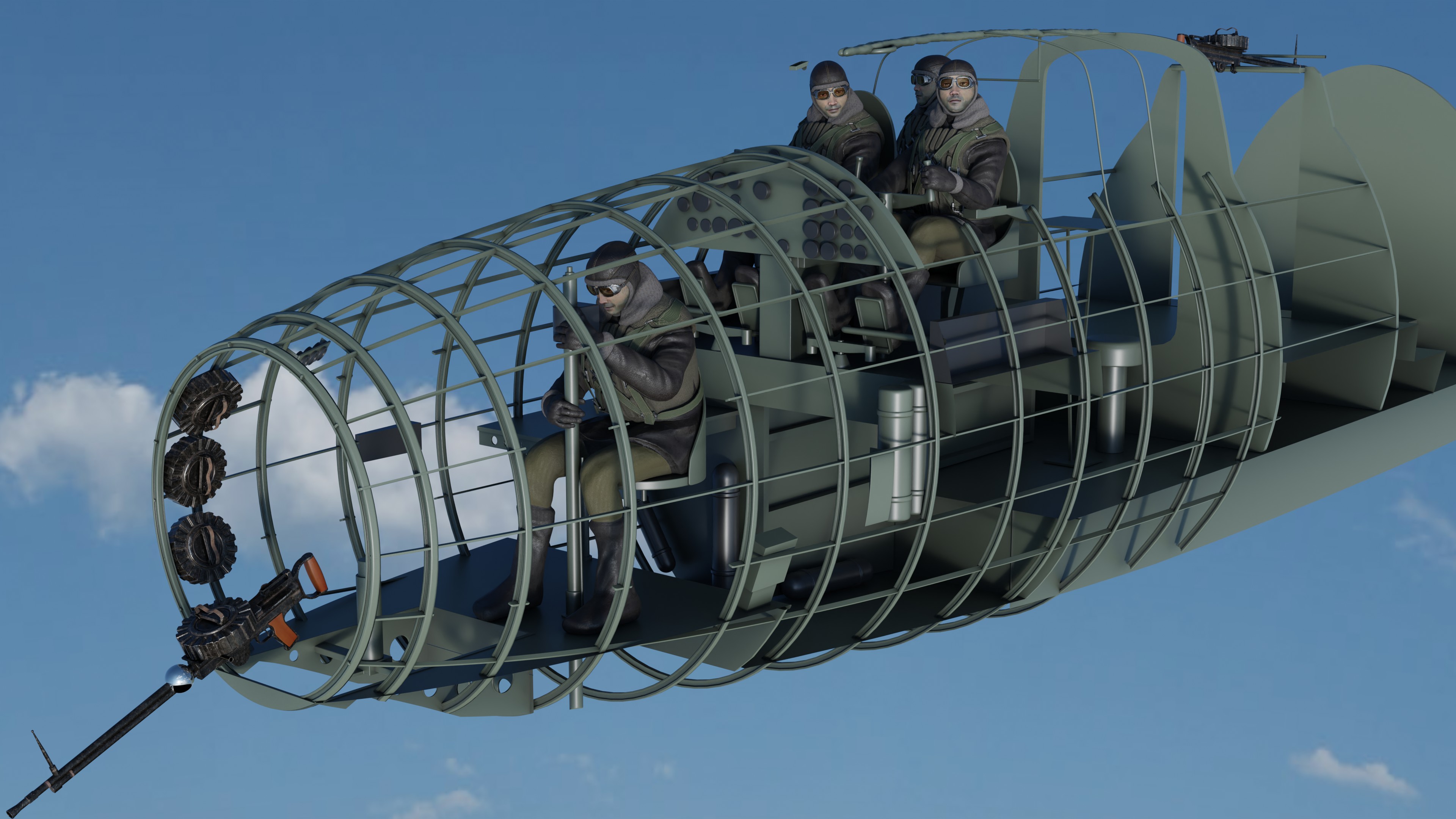
For example, here’s the base mesh for my Betty…
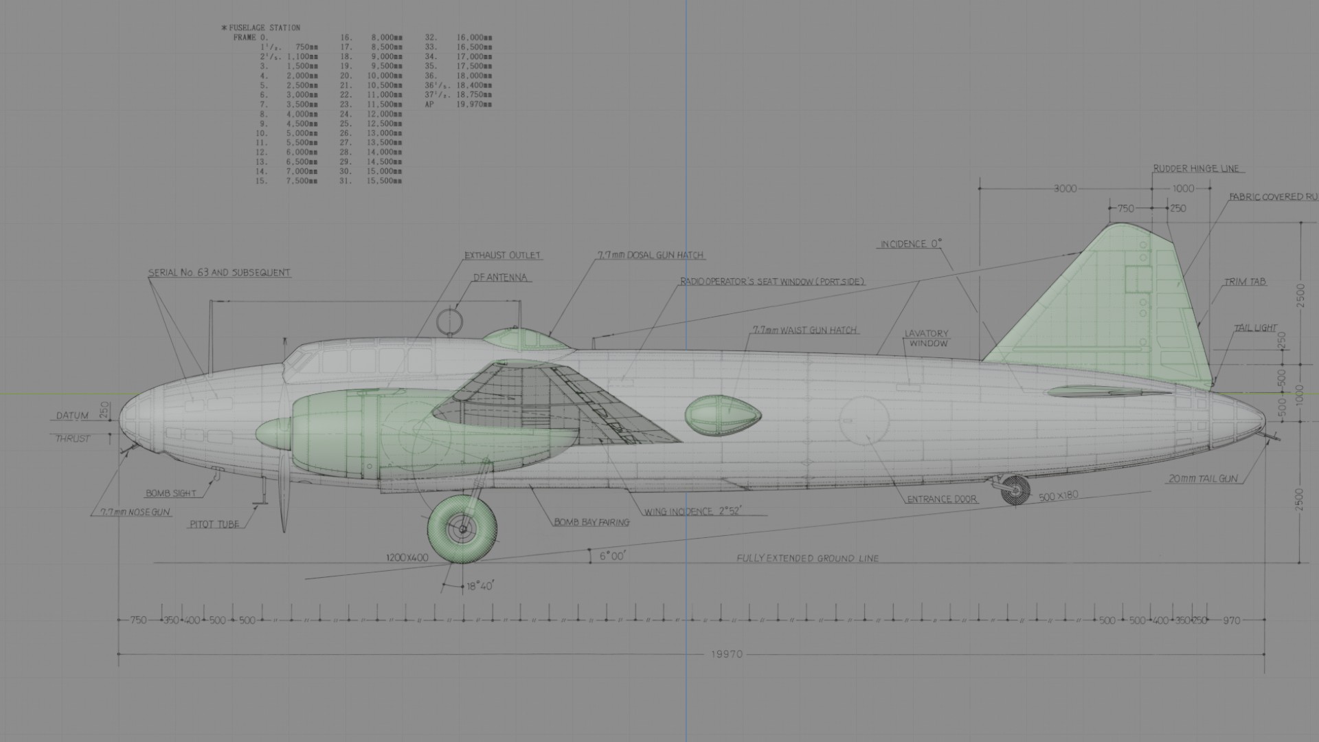


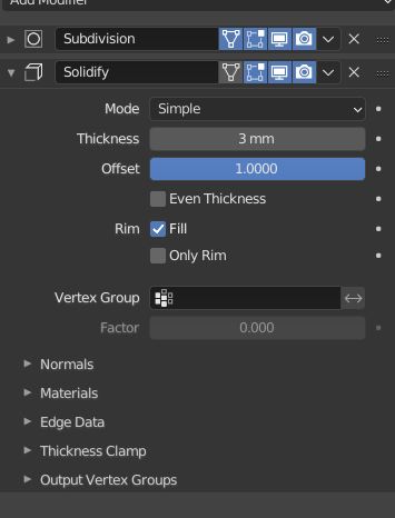
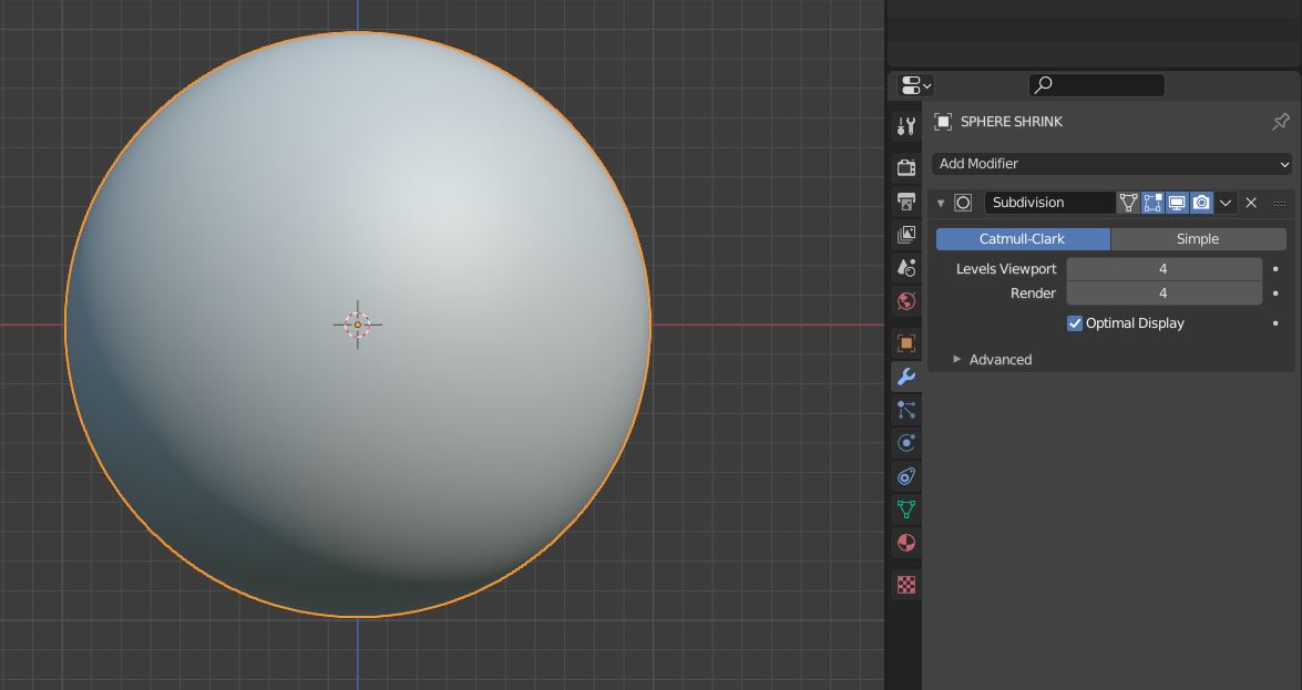
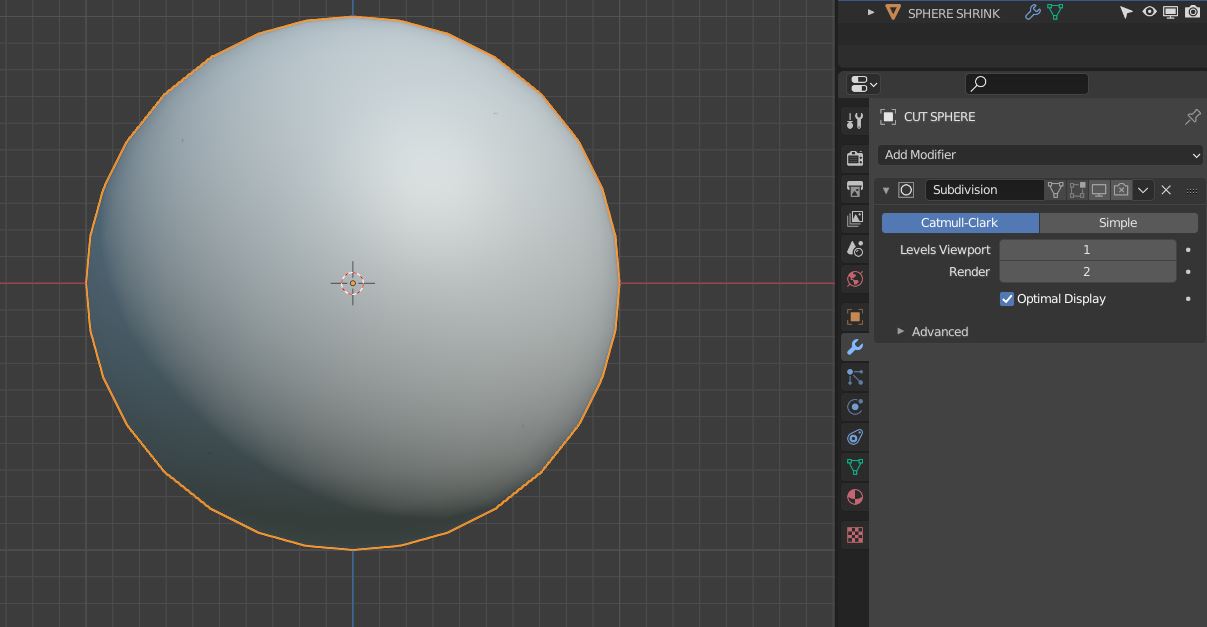
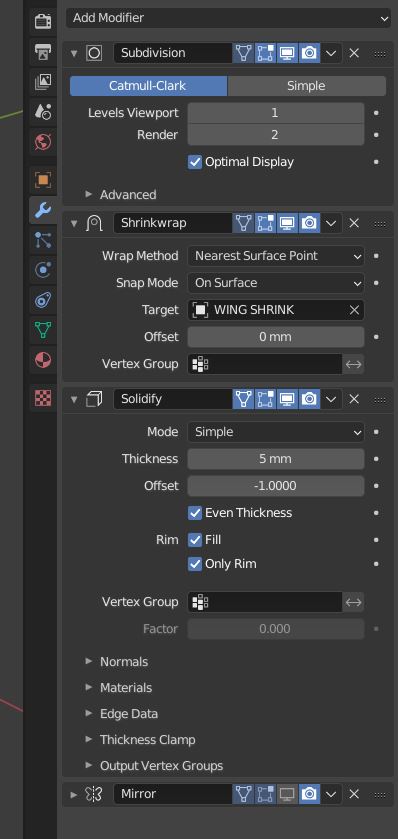
The wings, nacelles, fuselage, rear control surfaces, etc. are all made of independent objects using as few polygons as possible. Each of these objects has a subsurface modifier with RENDER and VIEWPORT levels set to 4. This makes the object very smooth and makes it work well as a base mesh.

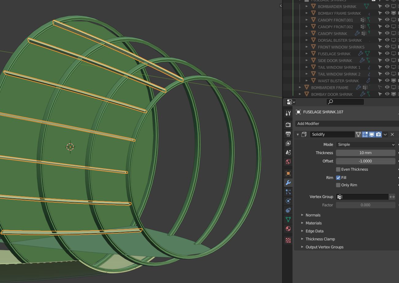
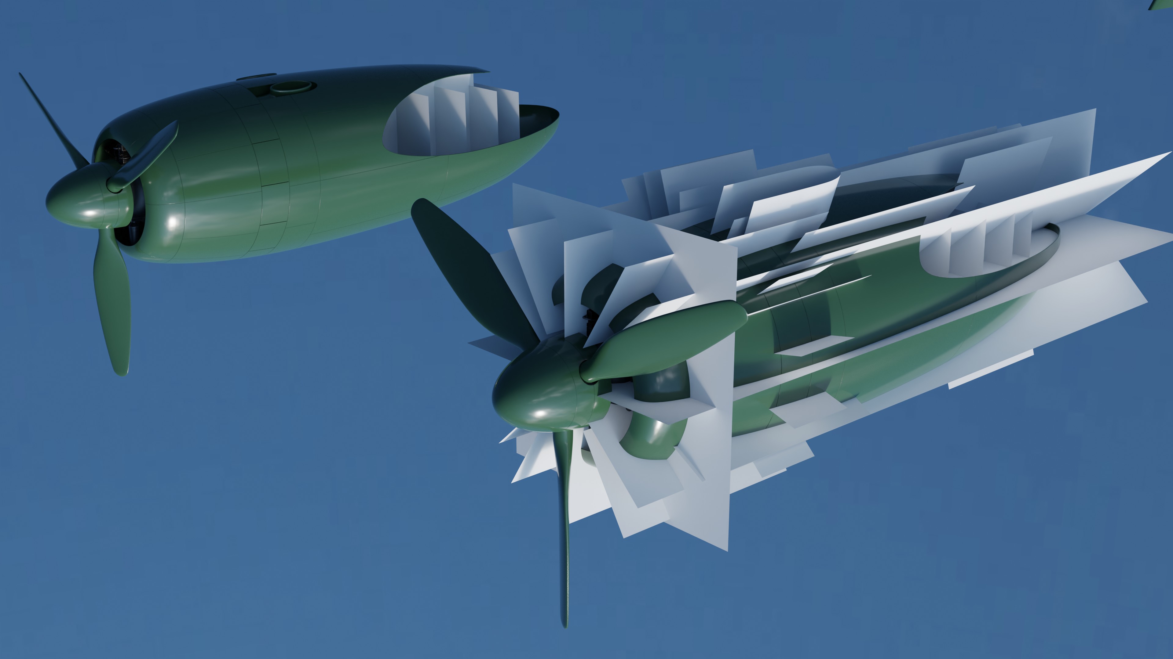
The next thing is to create planes that define the edges of panels. In the next couple pictures, you can see horizontal and vertical planes that define panel edges.
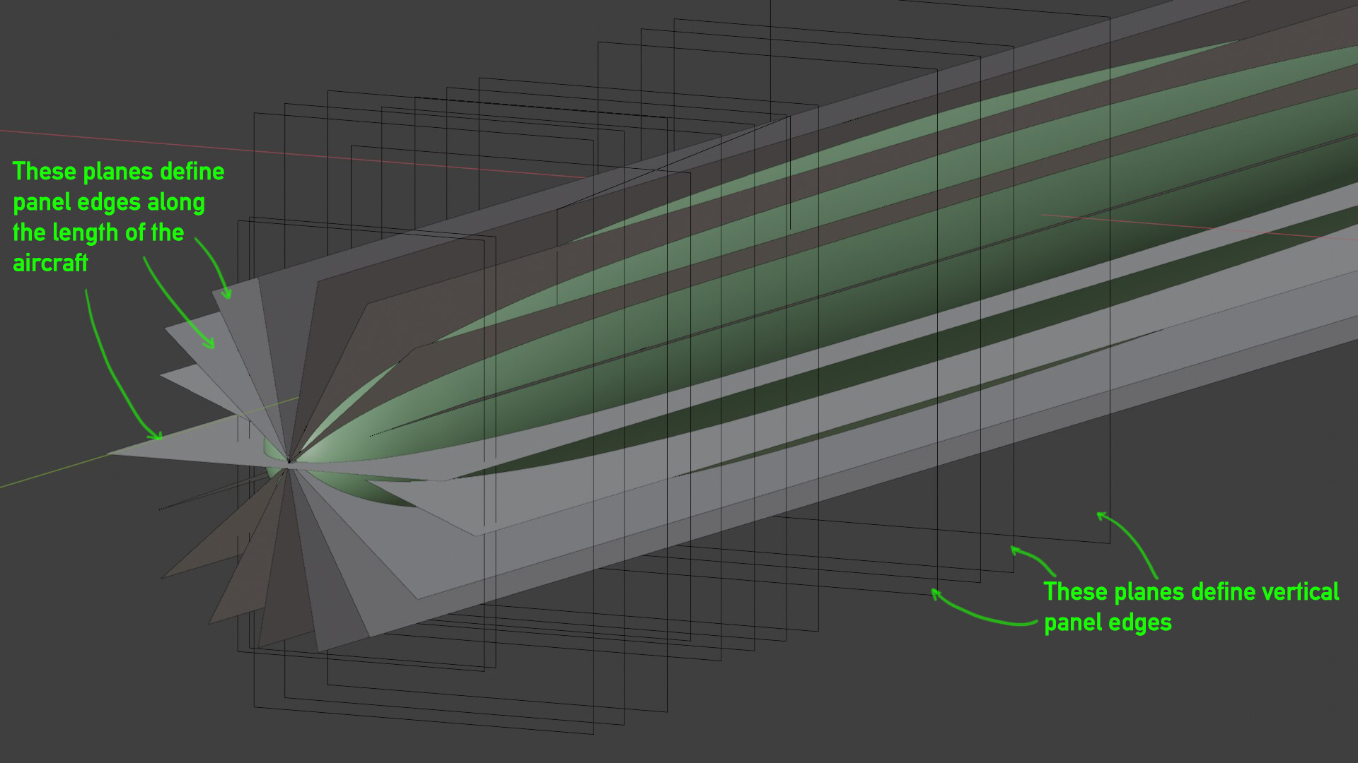

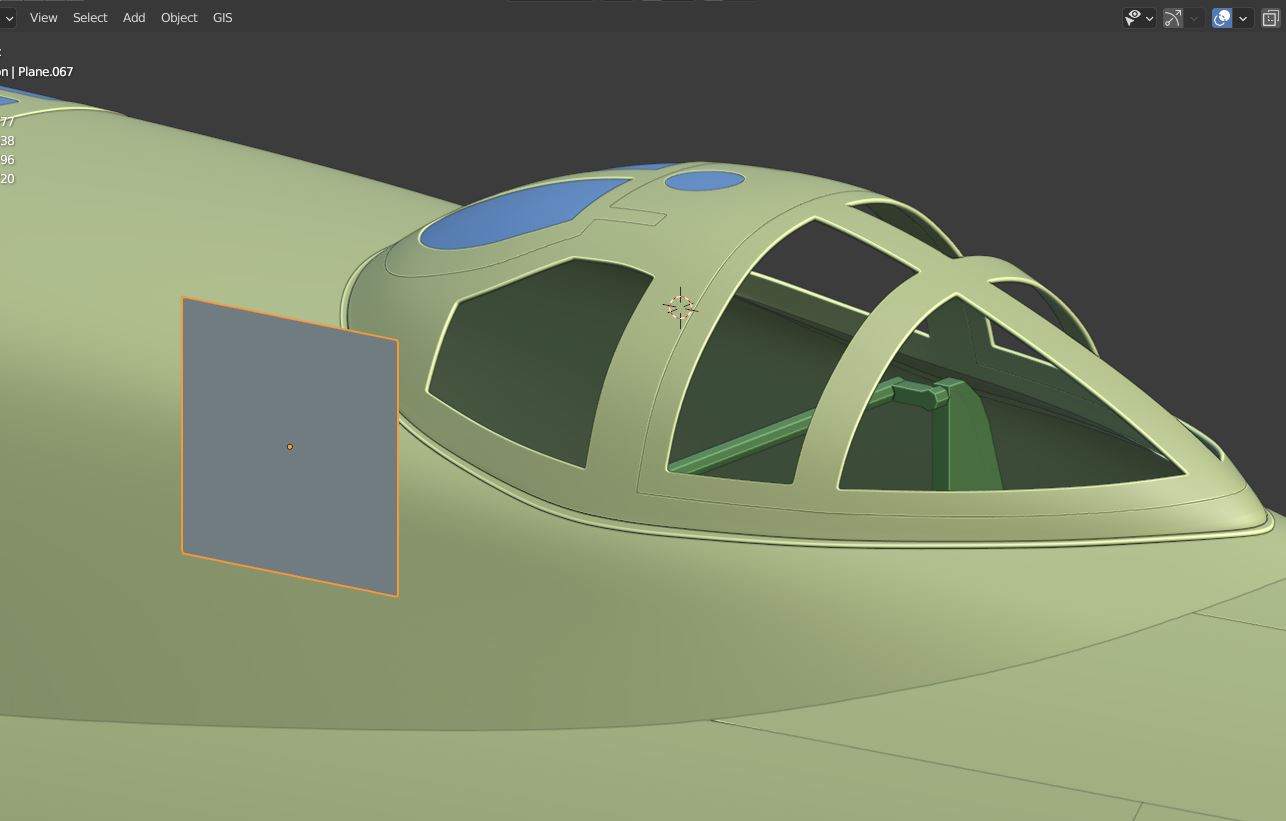
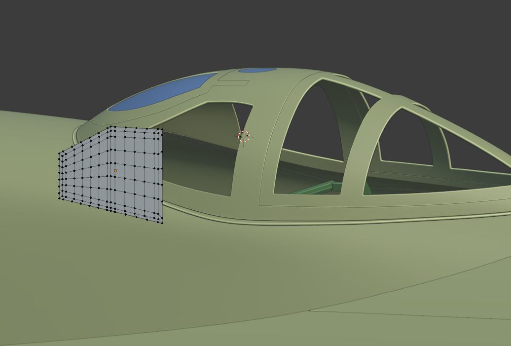
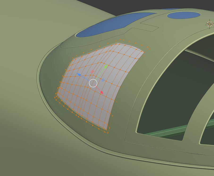
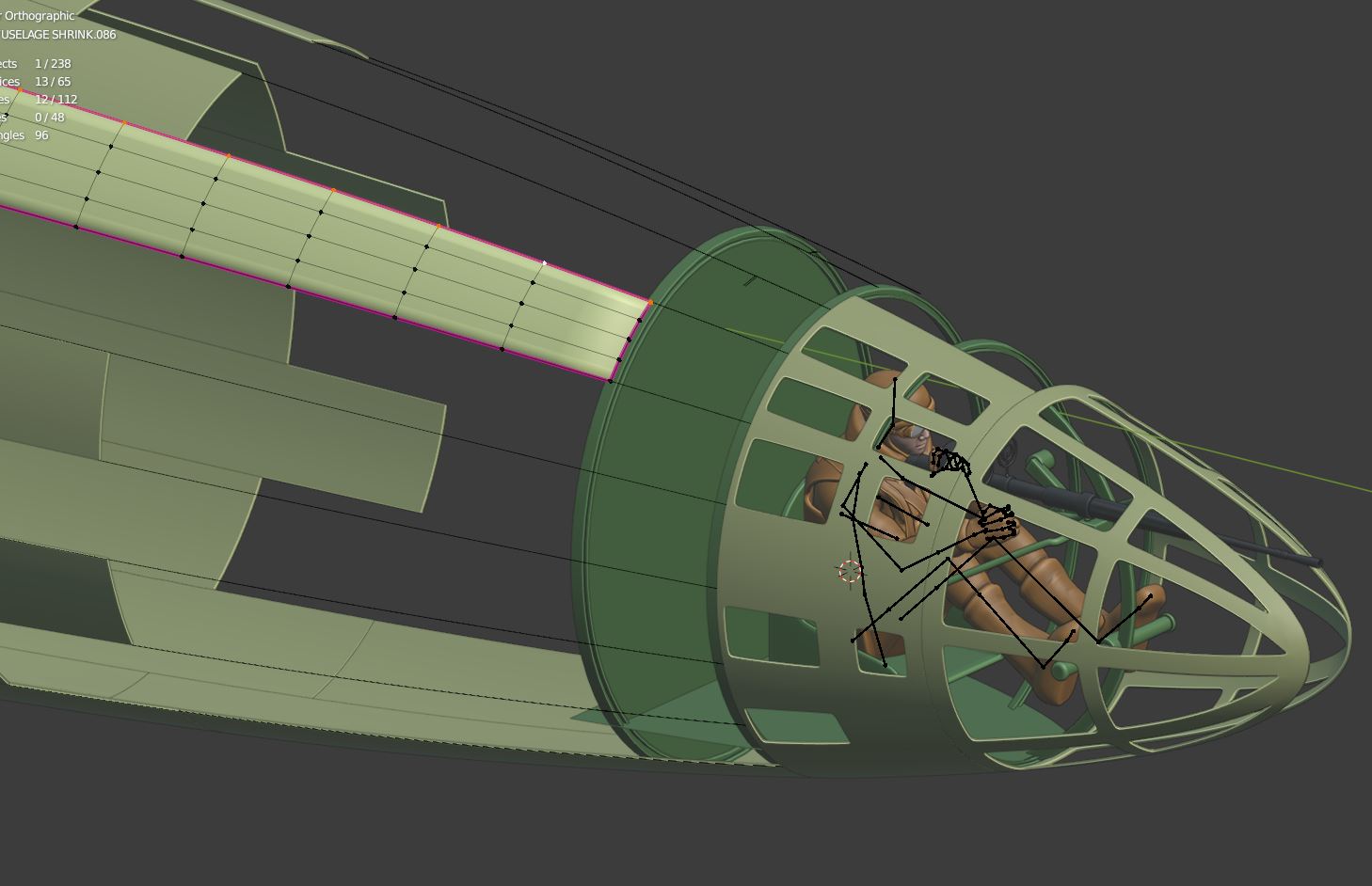
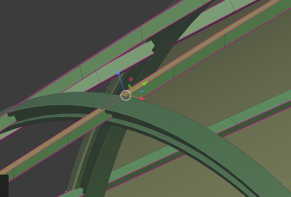
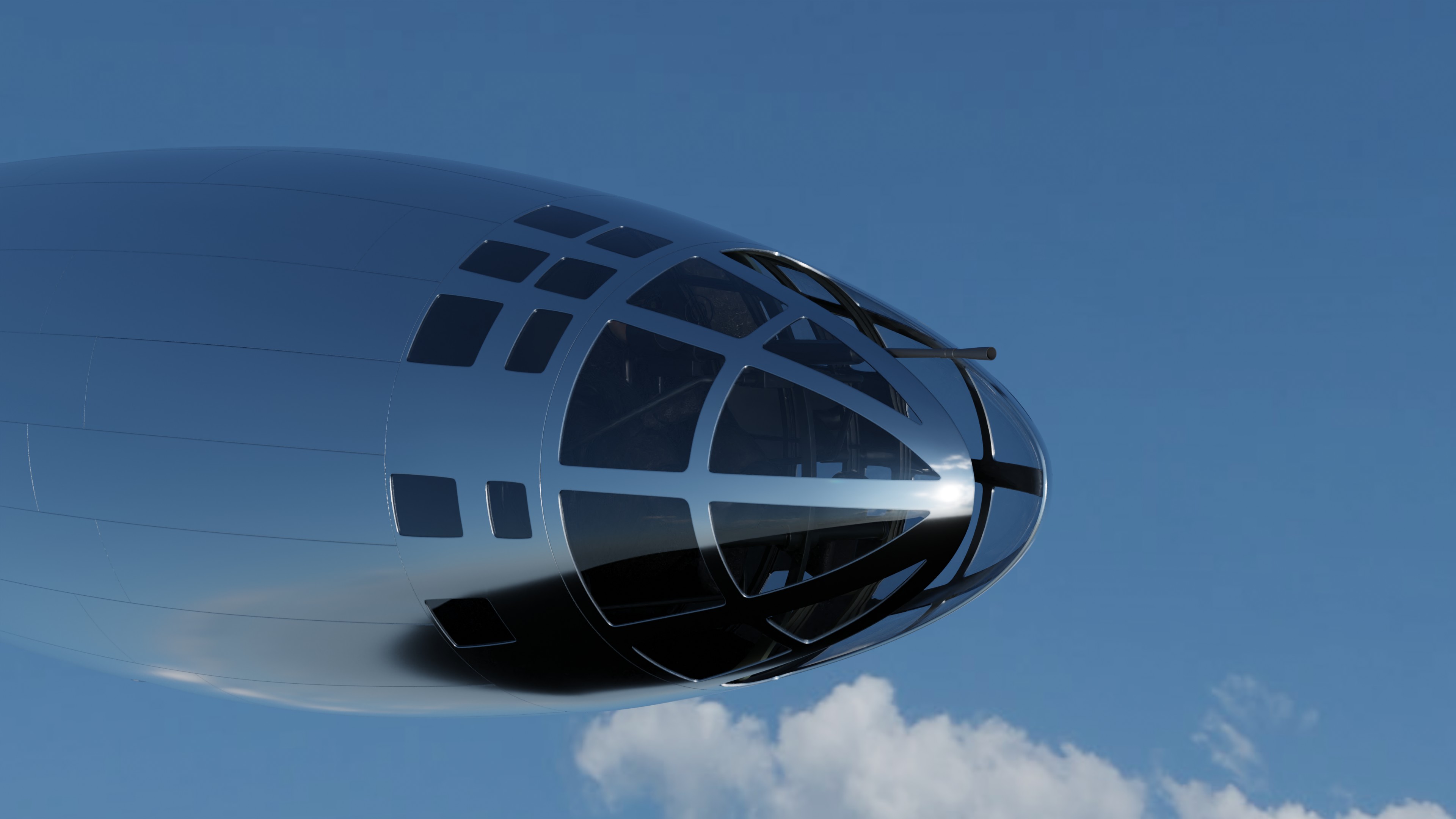
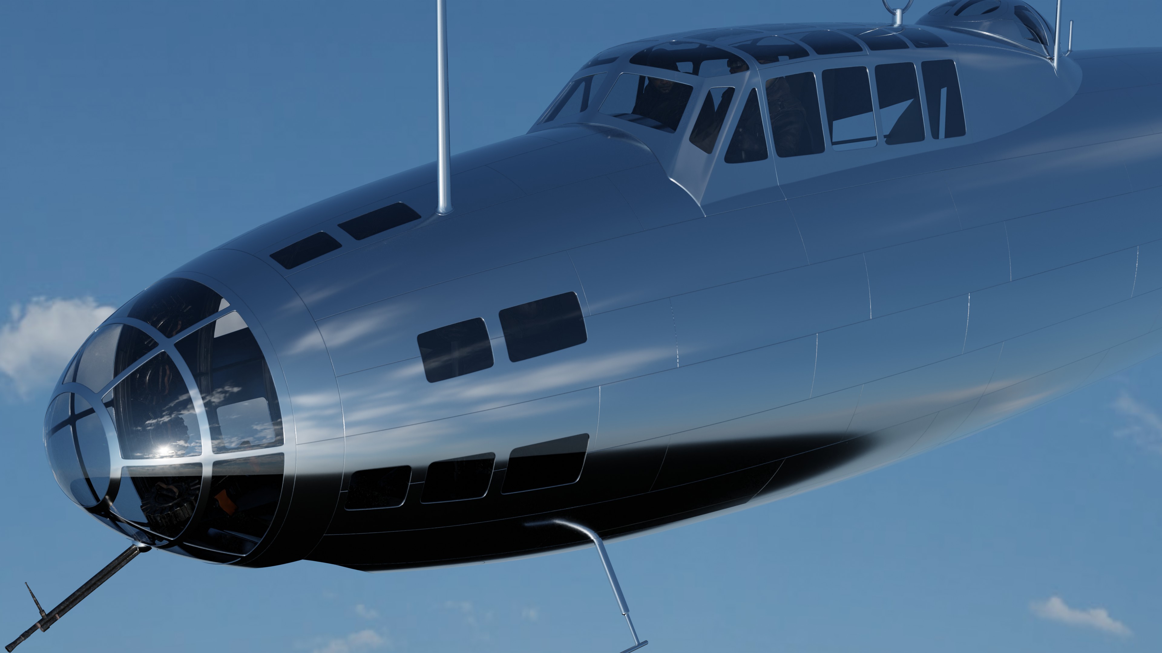
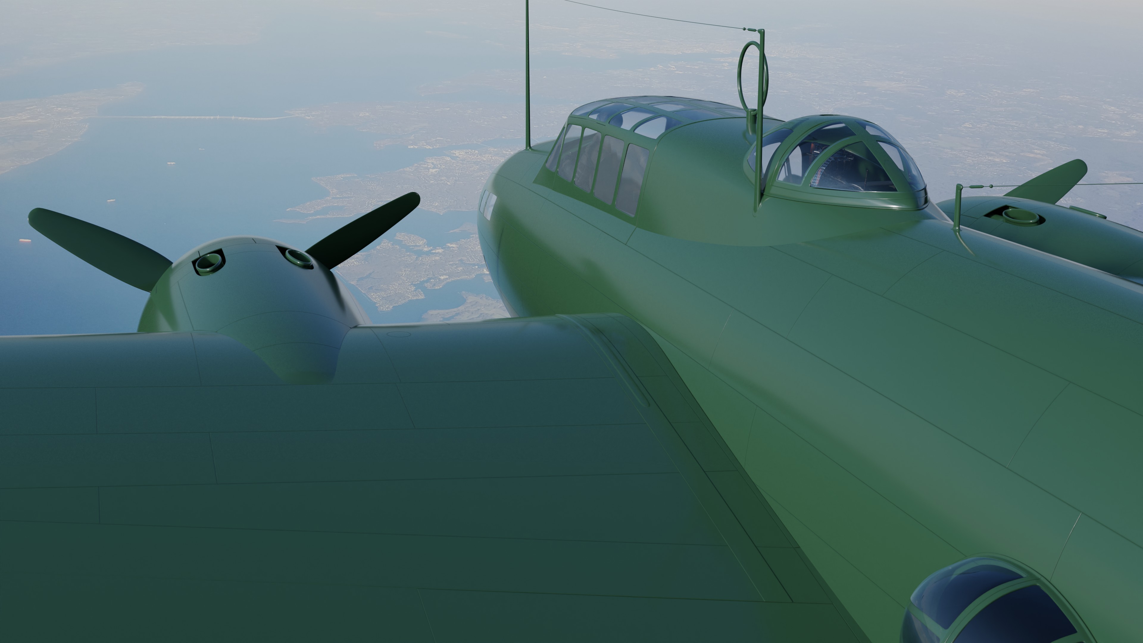
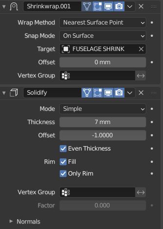
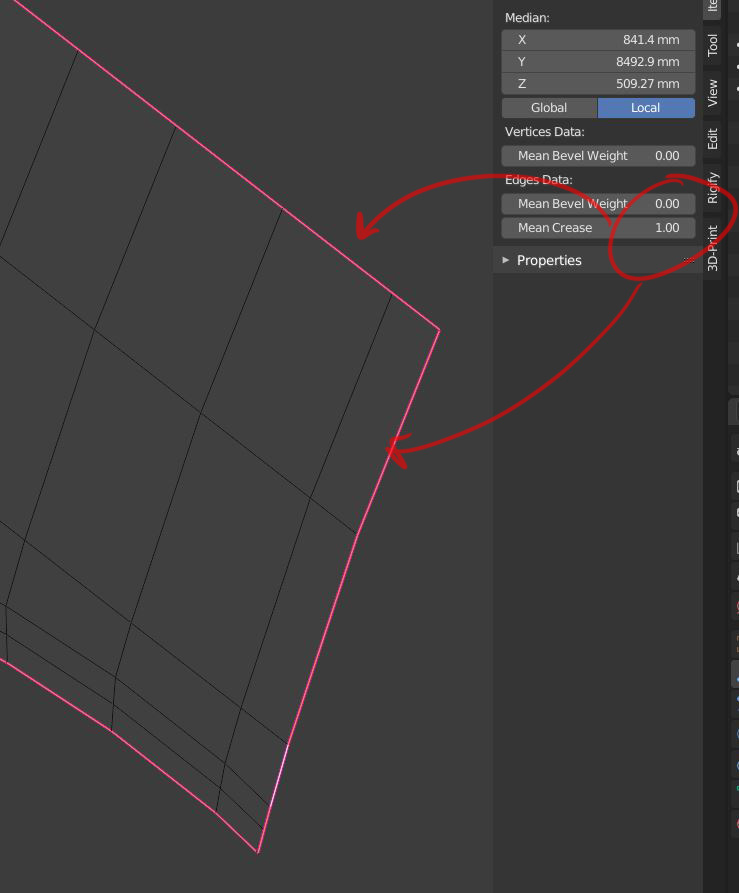
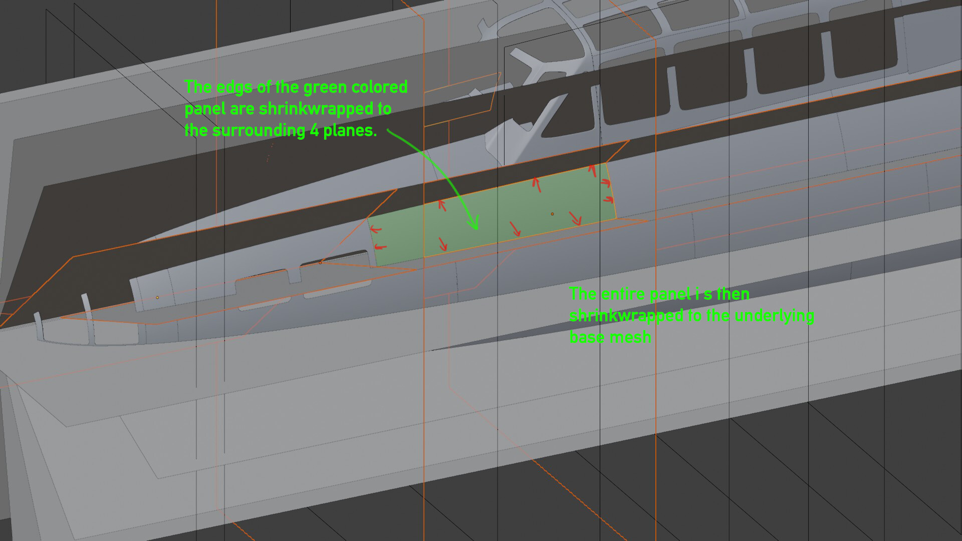
The exterior of the aircraft is re-topologized with individual panels. Each panel has its edges shrink wrapped to the guide planes surrounding it. This ensures that all panels have tight edges that always match their neighbors.
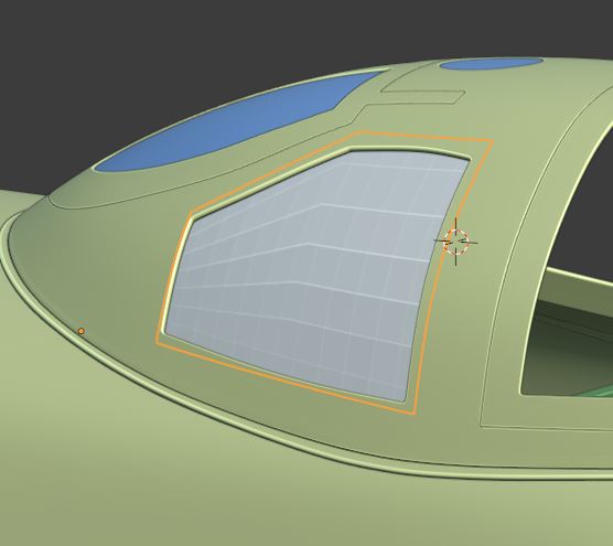
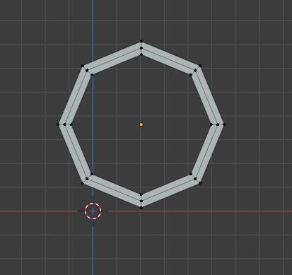
Around windows and other openings, it is sometimes helpful to create additional shrinkwrap targets. Below are examples of using rounded cubes to define the edges of window cutouts. The panels have their window edges shrinkwrapped to the cubes.

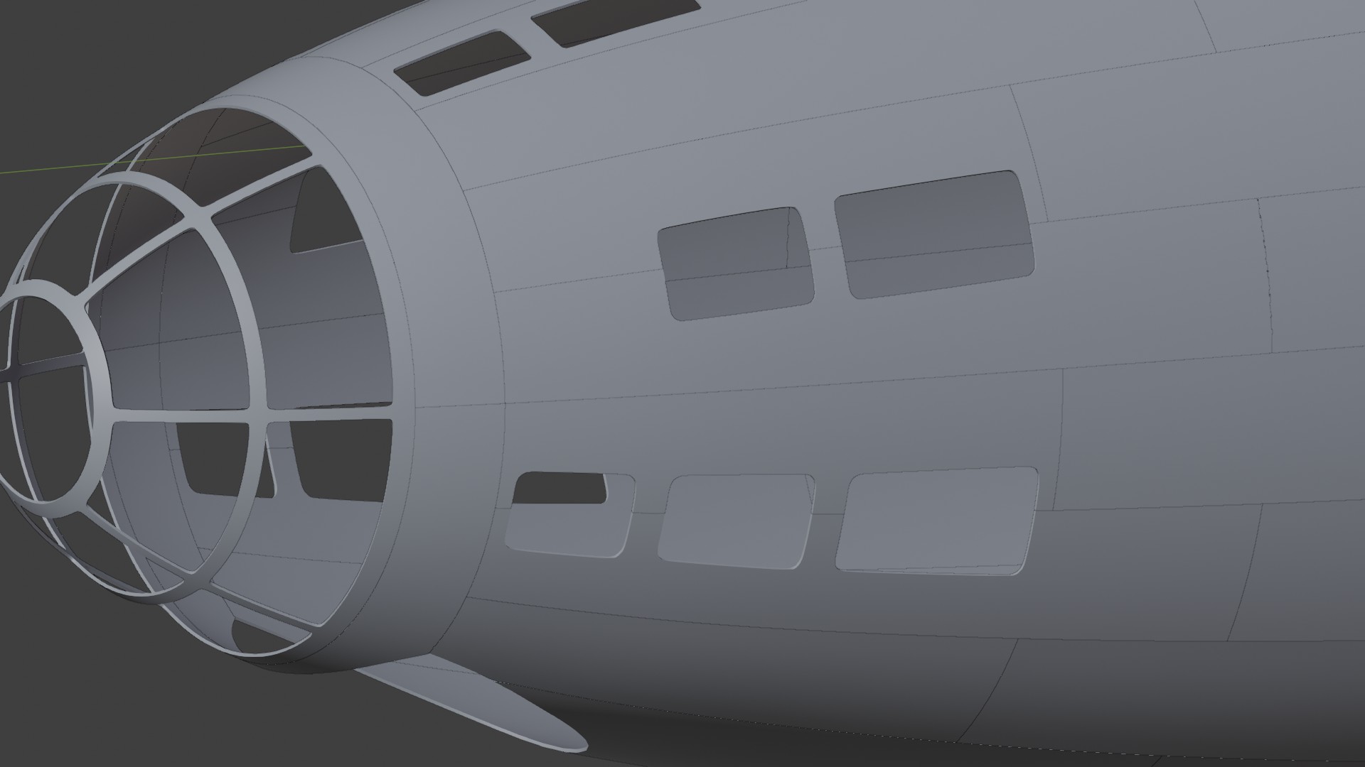
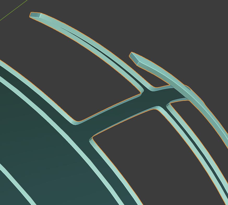
One of the biggest advantages to making individual panels is that it makes the overall topology easier. You don’t have to carry any more edge loops through the model than you need to since each panel is is own little project. Panels requiring complex topology can be placed next to simple panels without the need to blend edges from one panel to the next.
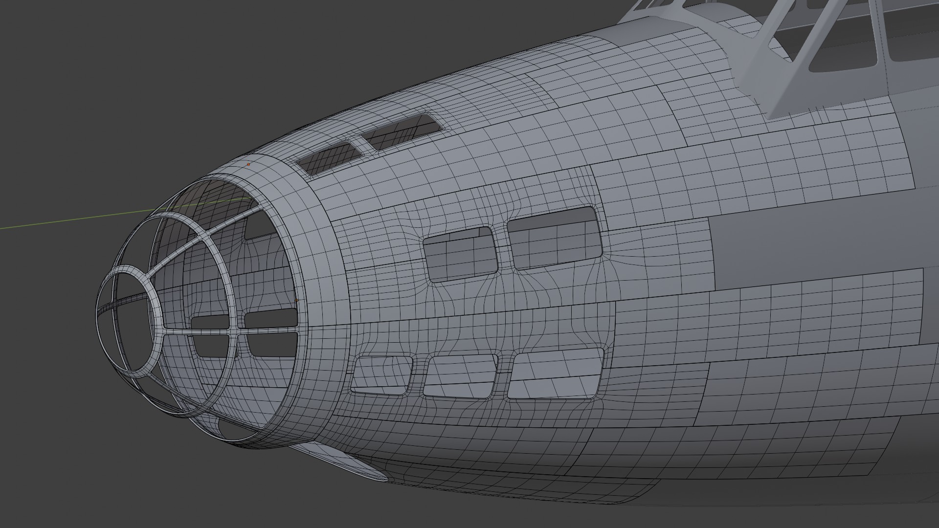
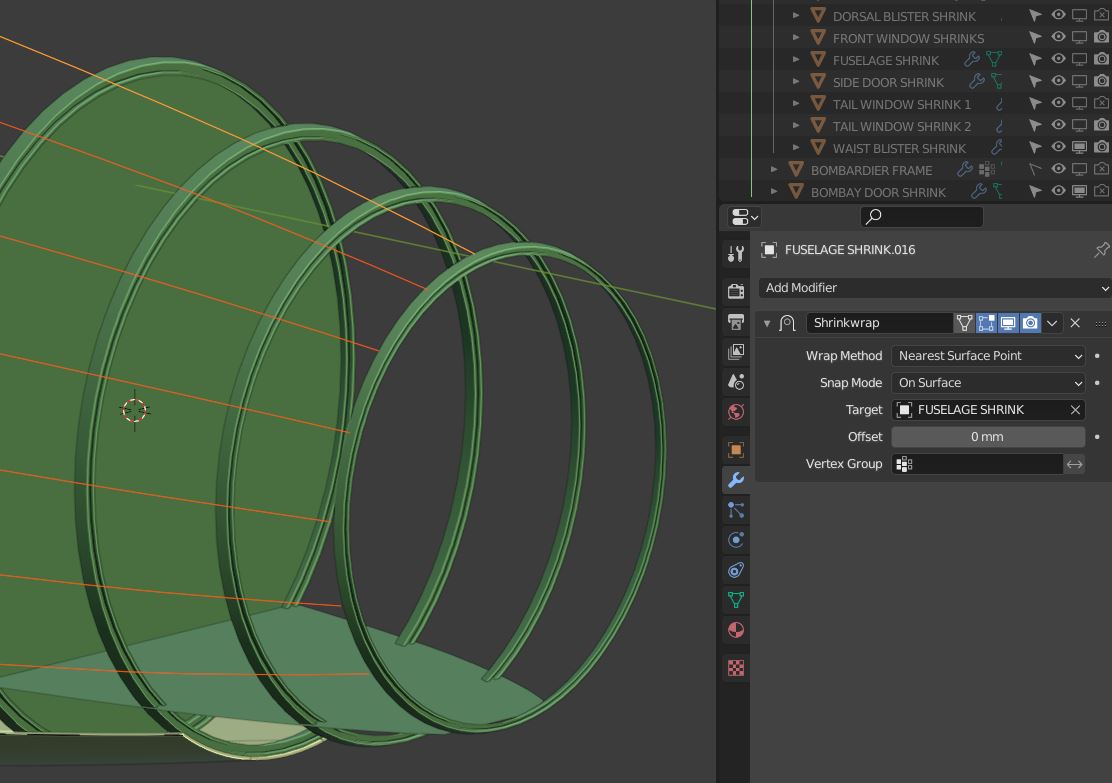
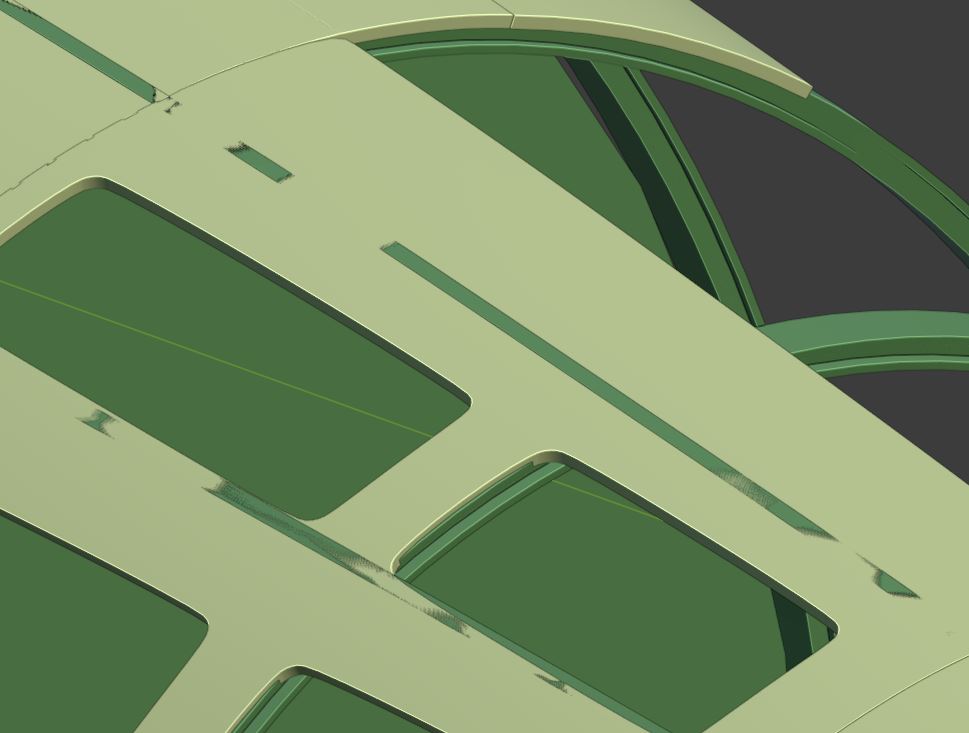
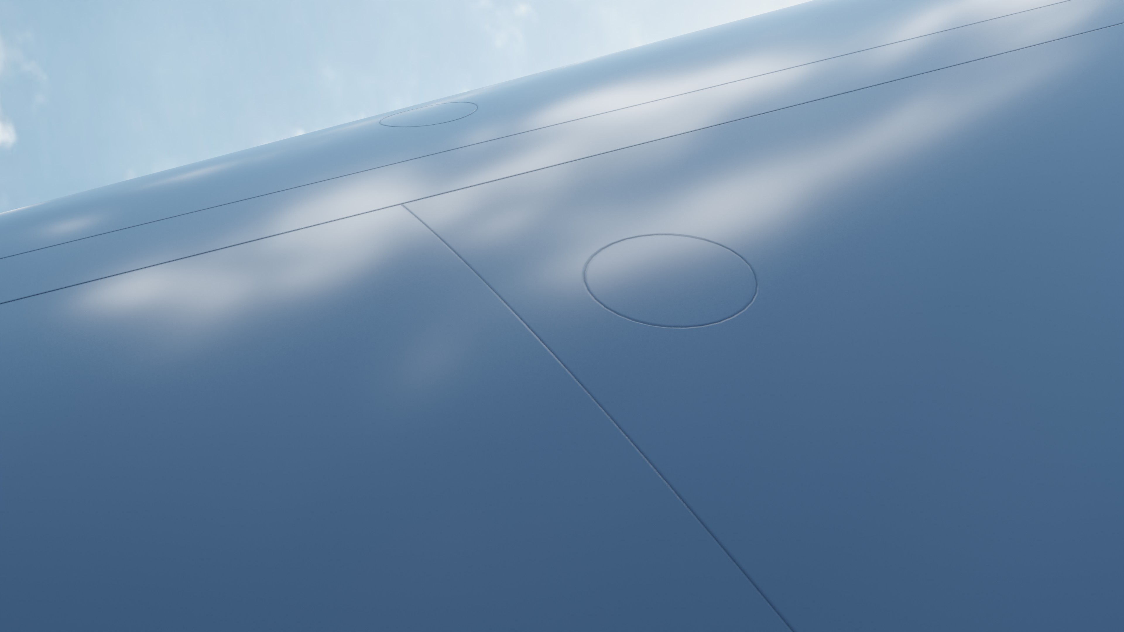
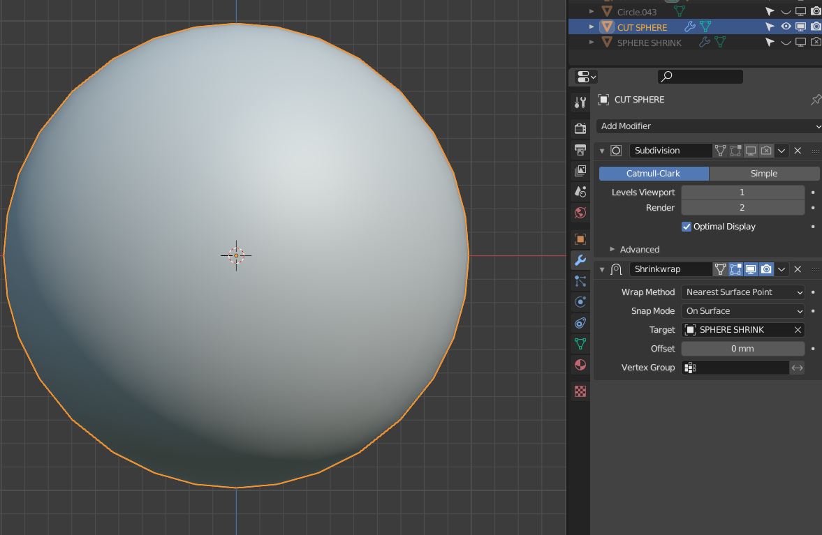
And finally, all the panels are shrinkwrapped onto the base mesh I talked about at the beginning of his post. This makes sure they are all smooth and follow the same topology. (The shader I’m using on this render has a bevel modifier on it. Otherwise, you wouldn’t be able to see the panel edges.)

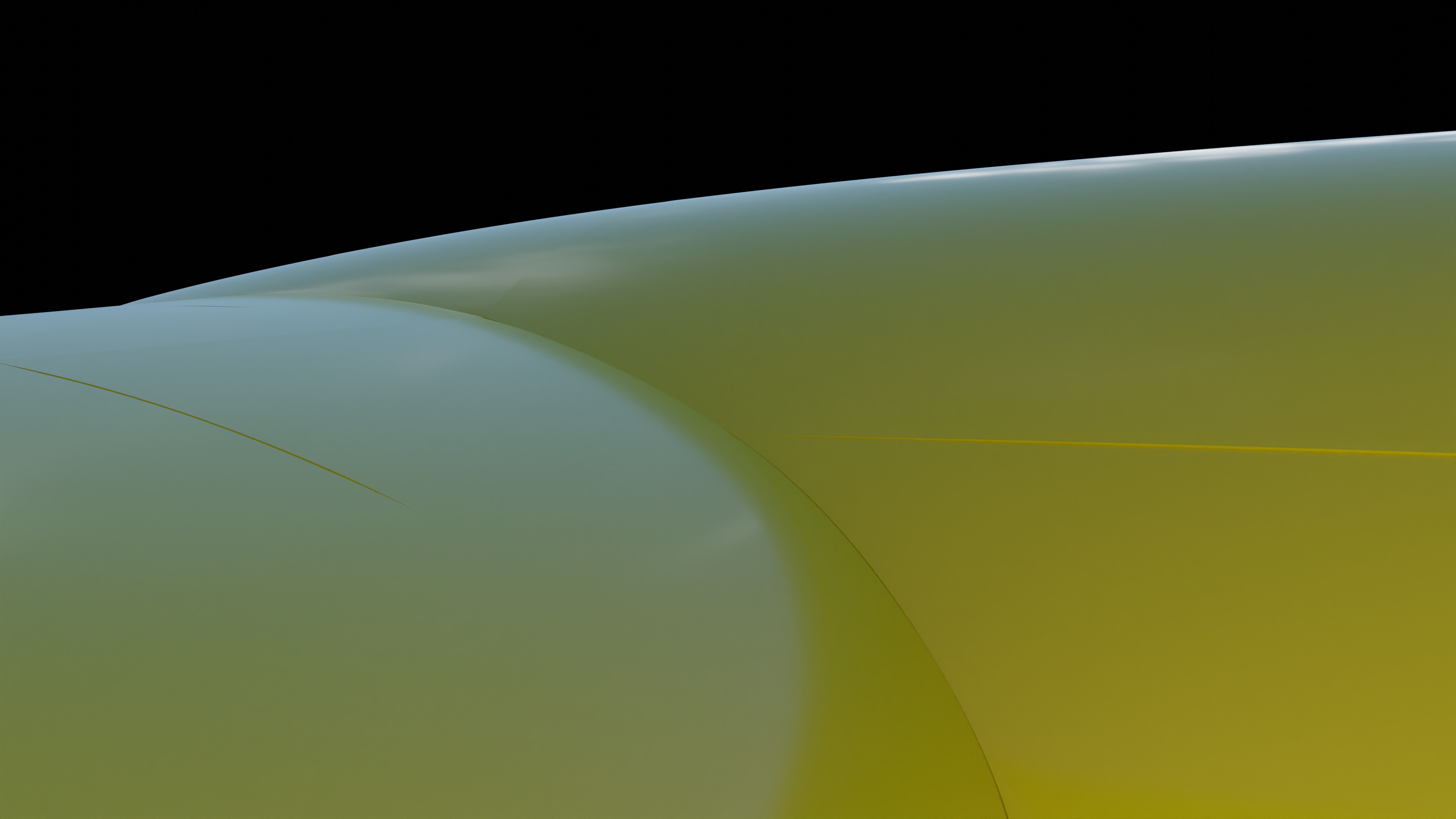
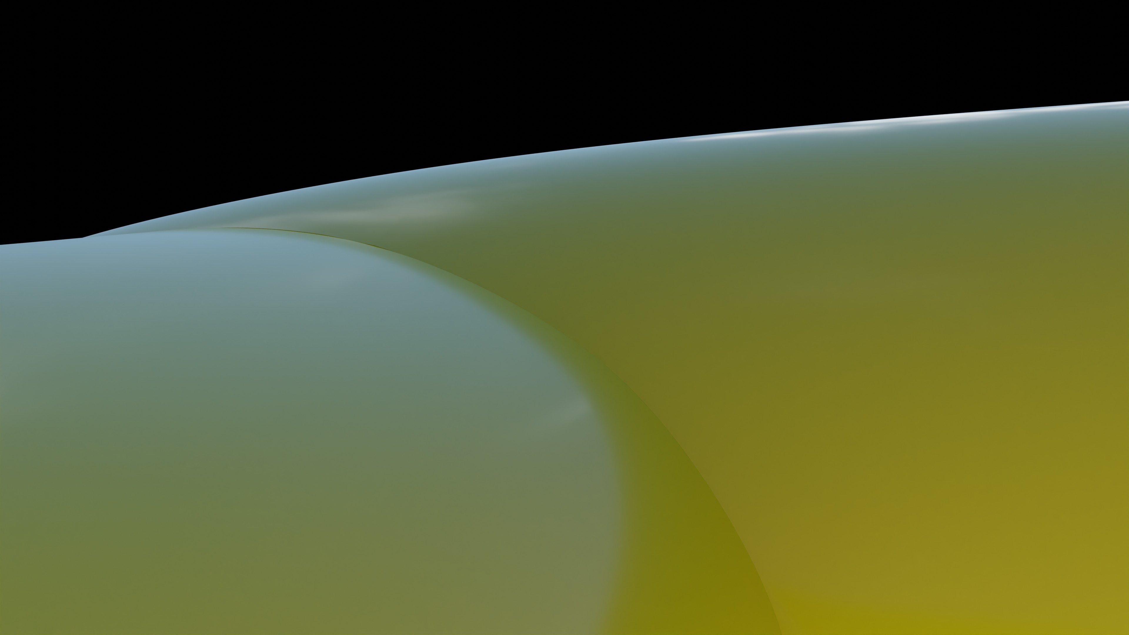
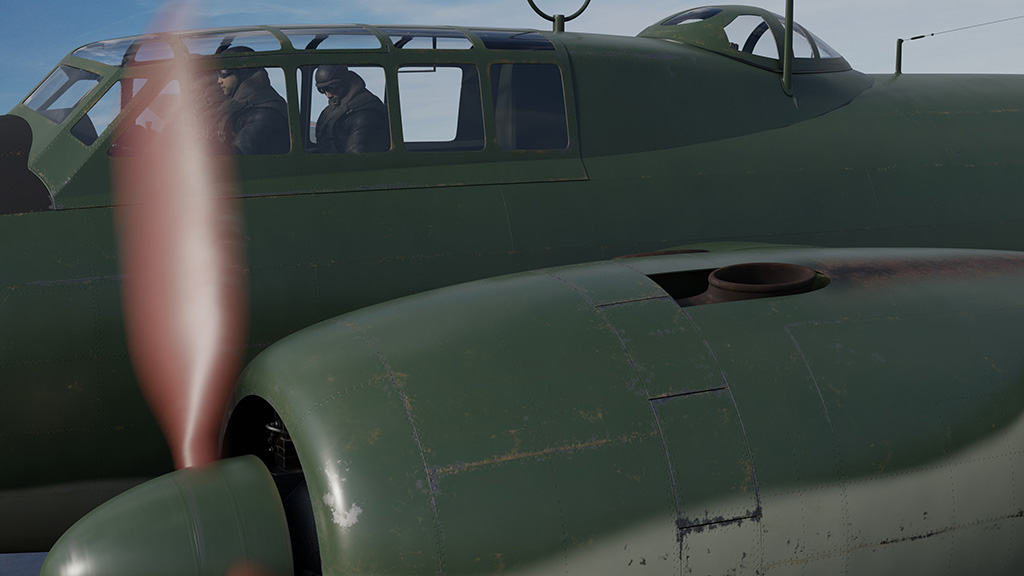
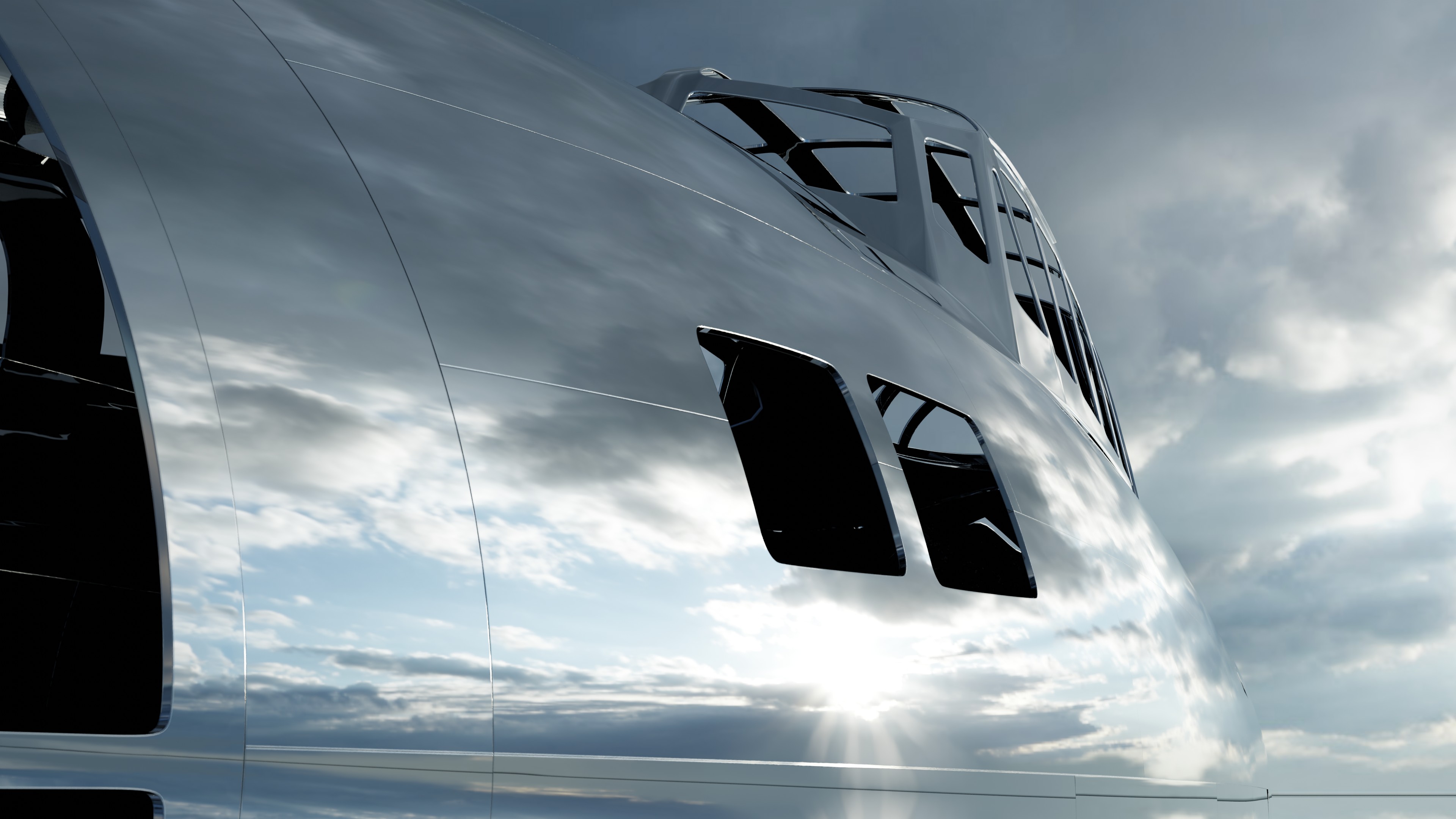
Even an oblique close-up showing the window cutouts shows clean cuts without any pinching.
Thanks for visiting. More later…