Bisect Mesh Node

Hey everyone!
I built a new node that bisects a mesh into two distinct parts. This is similar to a node shared here previously, but my version handles some edge cases better, keeps the mesh attributes intact (even interpolates them on the edge), and is much faster.

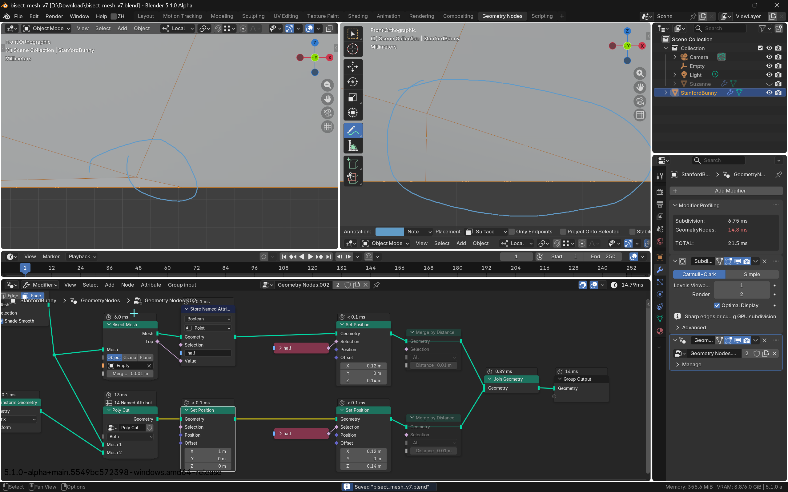
It has a couple of modes to define the cutting plane. In Object mode, it takes the XY plane coordinates of a given object, in Gizmo mode you can interactively move the plane around, and in Plane mode it is defined by a given position and normal.
(It’s a bit unfortunate that a Merge Threshold is necessary here, it just merges the newly generated faces in the cut with the original geometry, but there is not yet a way to do that more explicitly without a threshold)
For the impatient, here is the download:
bisect_mesh_v7.blend (192.5 KB) (CC0)
Details
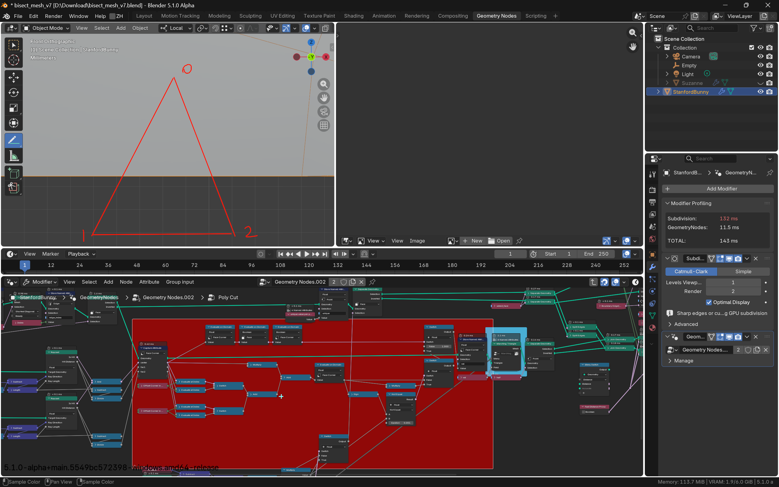
There are a bunch of tricks used in this node to make this possible, and I want to step through the implementation to explain some of them. I will not go through every detail, only highlight things I feel are noteworthy.

(The input handling of the node turns the given cutting plane definition into a matrix, so that we can transform the point positions and just check the Z axis to know on which side of the cutting plane we are. This is used in a bunch of places, so it gets a little helper group)
The first thing we do with the geometry, is to split it into two parts: one part is all the faces that do not cross the cutting plane, that is, they are completely to one or the other side of the plane. The other part is all the faces that have at least one vertex on one side of the plane and another on the other side.
The trick used here is to use the Weights input of the Corners of Face node to sort the lookup of the corners by the Z axis (relative to the cutting plane). That way the first index (0) will be the corner with the minimum Z coordinate, and the last index (-1) will be the corner with the maximum Z coordinate. We can compare these two to check whether any given face crosses the zero point.

(split mesh parts)
After this split a large part of the mesh can already be ignored, as we only have to actually change the faces in the part that crosses the cut. We start by turning all the faces in this part into curves with the Mesh to Curve node in Faces mode. This mode will create curves that follow the original ordering of the face corners and will propagate face corner attributes to points on the curve, so we can exactly reconstruct the faces later.

Now we are at the step that has the most complexity: We want to somehow slice these curves at the cutting plane. For this I built a helper group with the following semantics: Given a curve, delete all points with a negative Z coordinate, and add new points at the intersection with zero.
Example:

Deleting the points is straightforward, but the intersection points need some care. We start by converting the curve to a mesh, and keeping only the edges that actually cross the cut, similar to the face separation we did before. These edges are then immediately turned back into small curves, but these curves only have exactly one start and one end point (the vertices of the edge). This is done, so we can use the Trim Curve node to cut the edge/curve at the intersection point with interpolation of attributes from the end points.

We only keep the point at the cut from this trim operation, and merge it with the points from the original curve that were above the zero Z coordinate. All these points can then be turned back into a curve with a Points to Curve node. (I glossed over some details here, we also need to keep track of the ordering, so the new points are at the right position in the curve. For more, have a look at the .clamp_curve node)
If we use this curve clamping node twice, once for each side of the cut, we have split the original curve in two. To fill these curves with faces again, we employ another trick, and use the aptly named Curve to Mesh node.

If we enable Fill Caps, put the curve into the Profile Curve input, and only put a short curve line with 2 points into the Curve input, we get our filled curves (Just doubled for the 2 points of the curve line, but we can immediately clean that up with a delete geometry node). This is in the Loops to Faces nodegroup, if you want to reuse that elsewhere, I found this operation very helpful in general.

Now all that’s left to do is merge with the other, untouched parts of the geometry and set a couple of attributes to identify these parts as “top” and “bottom”. All these operations are carefully chosen so that they propagate attributes like UVs properly, and with a bit of cleanup to copy material indices and shade flat/smooth information to the new faces, this should basically keep everything from the original mesh intact apart from the newly added split.

And for performance: On my machine, Suzanne with 5 subdiv levels (1M triangles) can be bisected in 69ms, which is nice  (most of the time is spent in Merge by Distance, if you don’t need the faces to be connected afterwards it could be even faster).
Hope that helps, and maybe you learned something new!
David