Have a look at anisotropy and metallic in the principled shader.
Use a principled shader with the metallic slider set to max.
In the color slot, use a texture with the metal’s color variations, the metallic setting will automatically convert the color texture to the proper metallic reflection. Be aware that in you images, the metal’s actual color is subtle and most of the color you are seeing is from the surrounding objects being reflected.
Then, you will need a roughness texture. Find a black and white smudge texture and apply it to the roughness. You might want to pass it through a color ramp for more control.
Finally, for a metal to look right, you will need stuff around it that can get reflected, or the metal will look really flat. This means that the object should either be placed in a larger scene or have a world background.
1 Like
I tend to use one or two hard mixed anisotropic shaders (GGX, maybe also Bechman) and sometimes in combination with Glossy shader for edge reflections (based on layer weight/facing). GGX at roughness 0.3 aniso 0.7 or thereabouts, with Bechman at roughness 1-2.5 and aniso 1. Low roughness GGX like this may not stretch light well enough, and too rough will make it look like, well, too rough. I supplement with Bechman as this can stretch light sources very well (like a well but not perfectly polished copper brewery tank) although it’s actual reflections look like isotropic roughness. Glossy on top depends on what I observe in the real material or if I even care; typically brushed steel become a mix of anisotropic reflections and isotropic reflection between some grazing angles - at full grazing angle there may be no anisotropic visual left at all and it’s just a mirror.
For this particular one? Maybe a GGX would suffice? Would have to test. That’s the shading aspect of it. For sake of simplicity, I would use UVs to drive a seamless pattern as well as the anisotropic tangents. Look on youtube for how to setup 2D space in order to create seamless 3D and 4D textures that wraps around - only 3D is required in this case. Using that to drive a 3D voronoi, I’d use the hue output-0.5 time low value to drive the anisotropic rotation, and use the v output to mix some colors and call it a day. Other than for scratches, these object don’t have any bumps as part of the brushed metal part.
i cannot see any aniso on this metal !
looks more like some SSteel dirty and some roughness
Note: some sample file would be nice to show results or other methods !
roughness is a bit low here
and may be add some noise patches over !
happy bl
I agree that the colour is mostly due to reflections and lighting, also a bit of grunge roughness.
But I think there is a bit of aniso, on the left cycles with aniso on the right Eevee without.
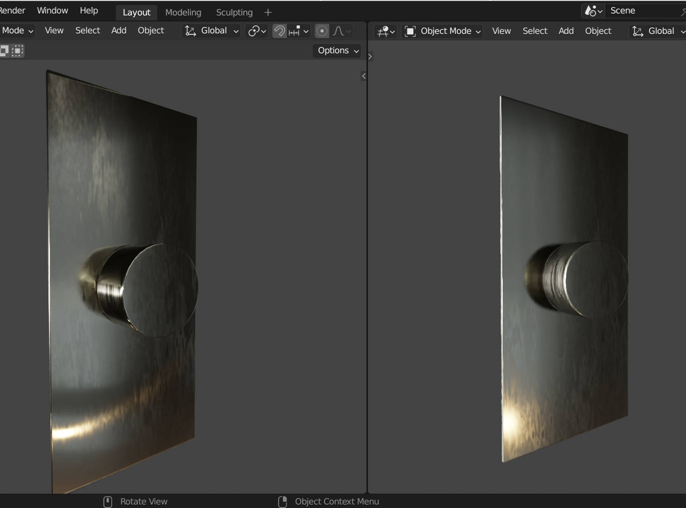
The shader is very simple a bit of grunge roughness and aniso.
It could probably benefit from a few “micro” bump scratches.
The colours come mainly from the HDRI reflections and an orange light (I did tint the metal a bit brownish).
1 Like
Thanks for the replies guys, So i desaturated the references to get rid of the coloured reflected lights and used that as a reference instead. Ended up with something like this:
Just used some stretched noise to make the pattern procedural and overlayed a slight tinge of colour on top of the base metal. The brushes might still be a bit strong but with a bit more adjustment hopefully itll get closer to the end product
2 Likes
show nodes set up at least so we can see how to
and if possible with sample file
thanks
happy bl
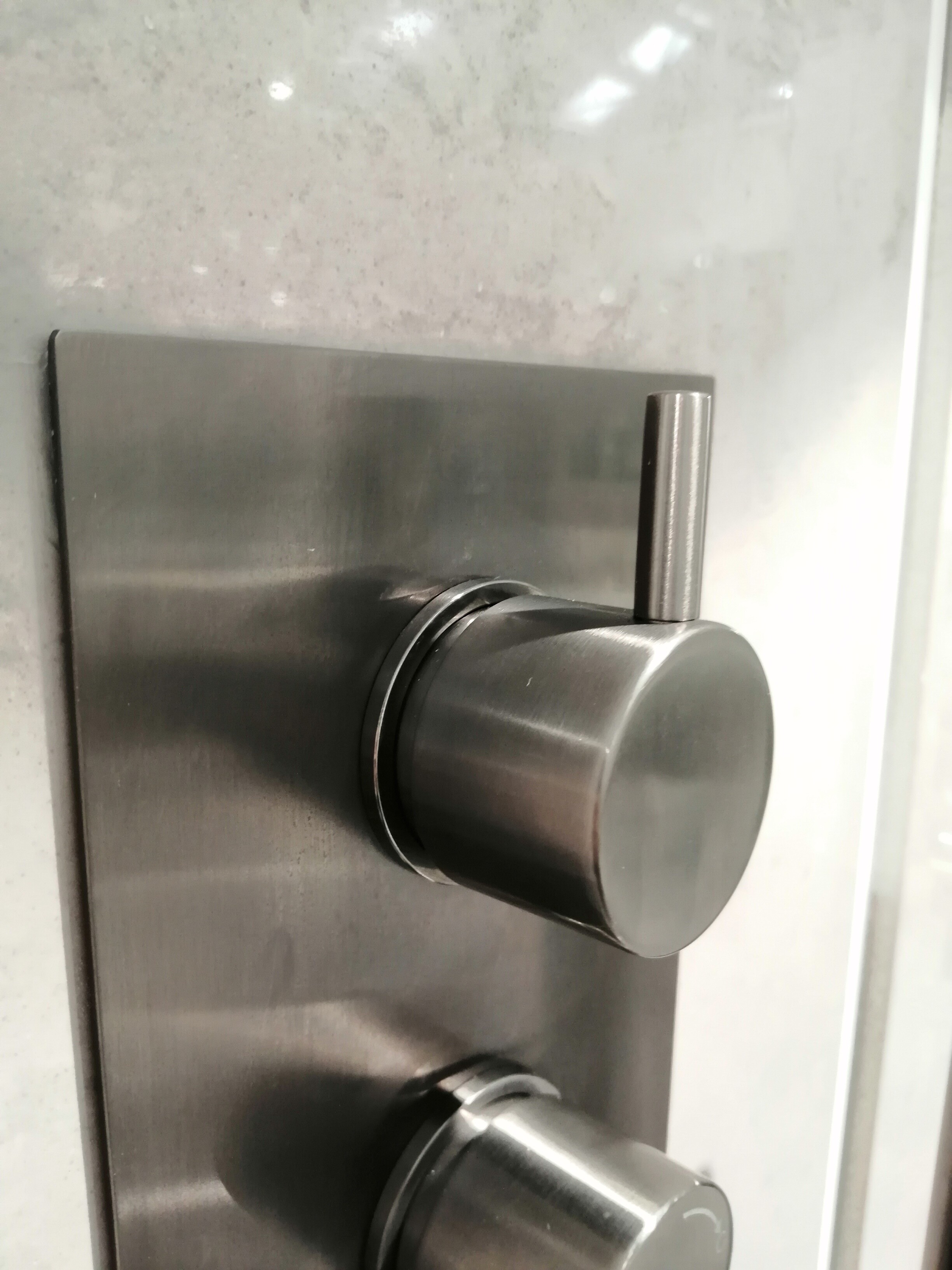
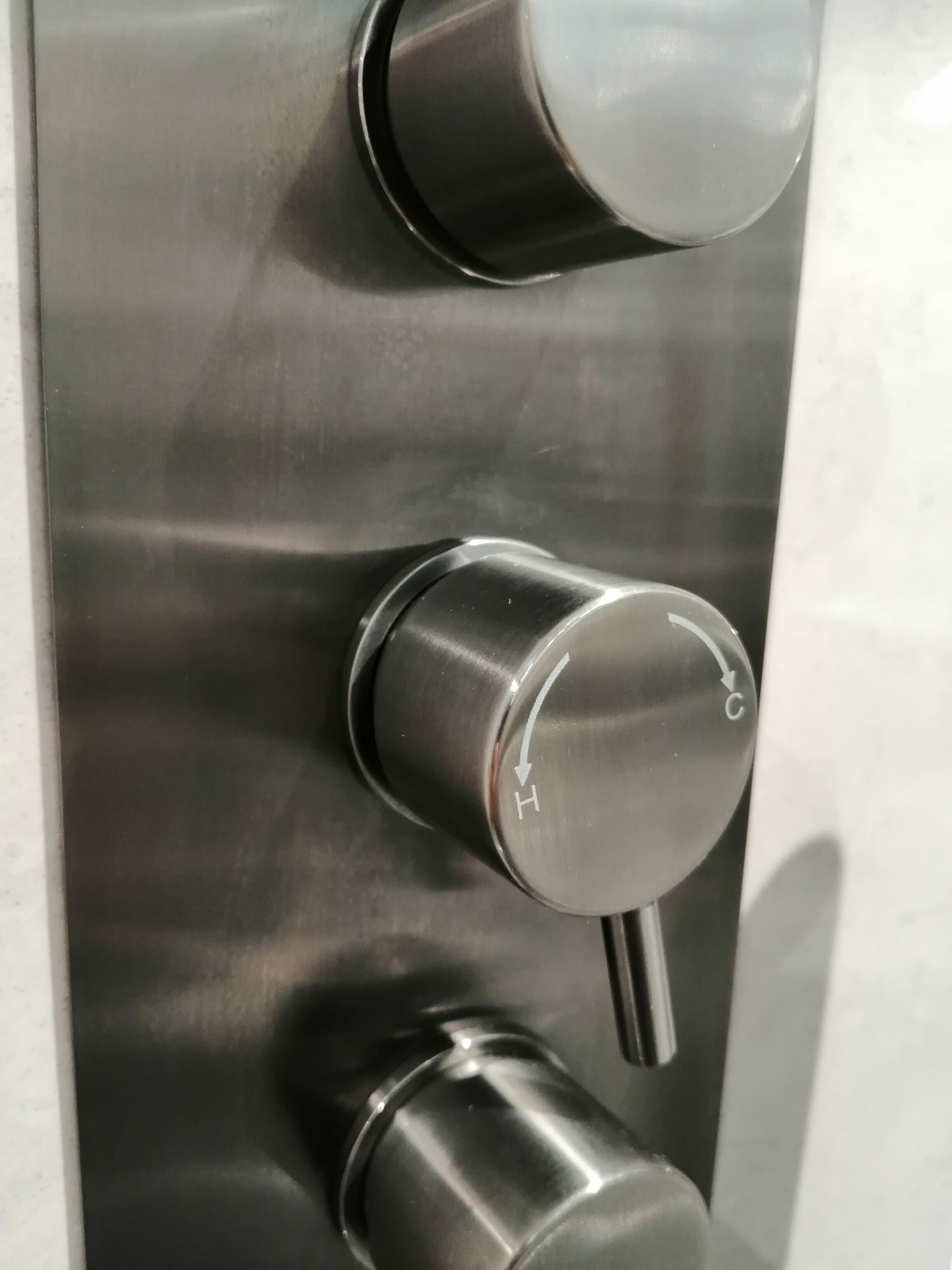
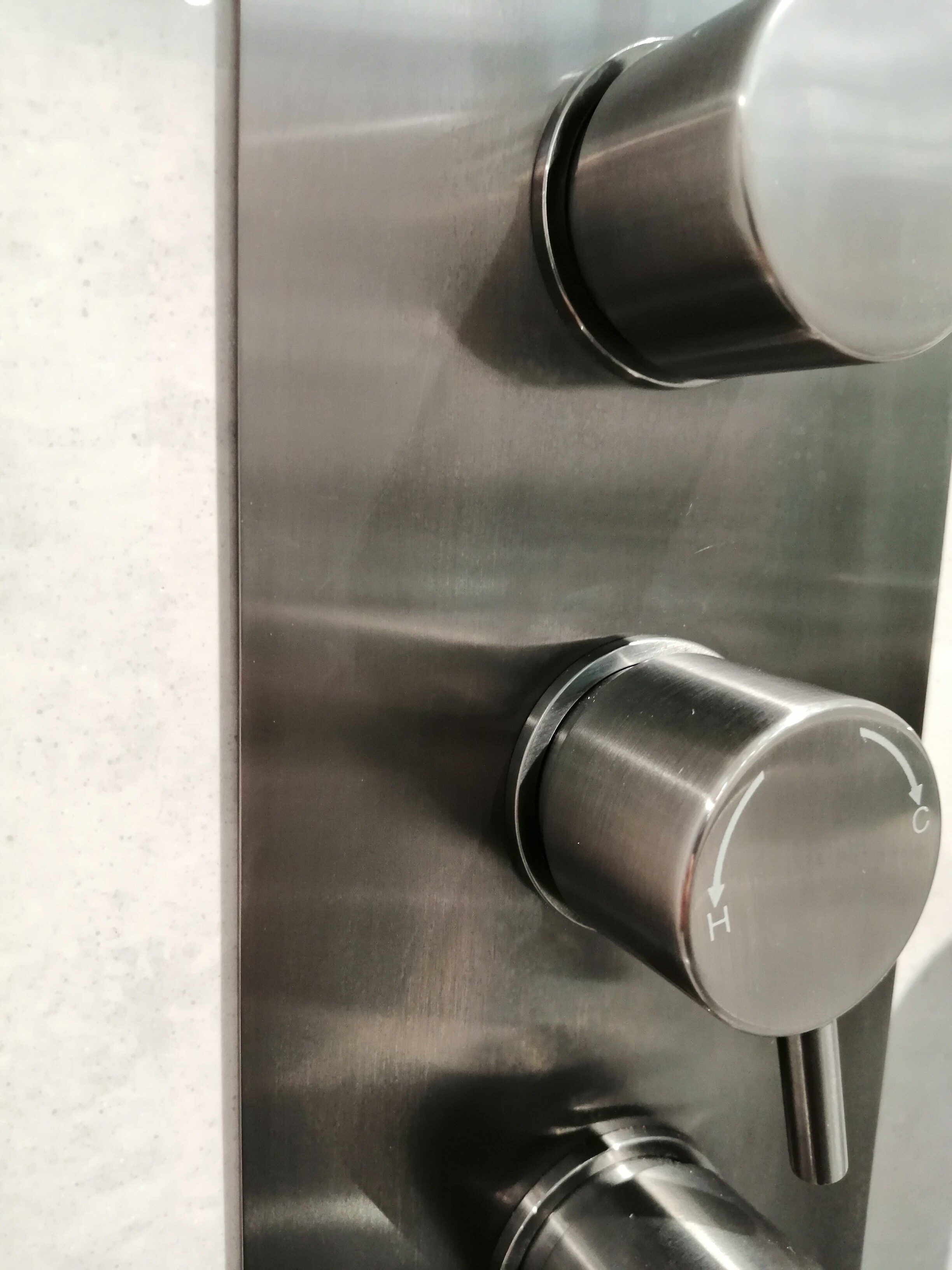
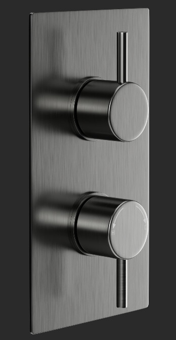
There is usually some level of aniso in all metals. From either machining tool marks, brushing direction, or unfinished directional polishing. Yes you can obtain a perfectly polished surface, and also a more matte or satin finished look. In this case it looks like the flat surface of the knob has been brushed with a belt, leaving directional marks rather than radial ones.
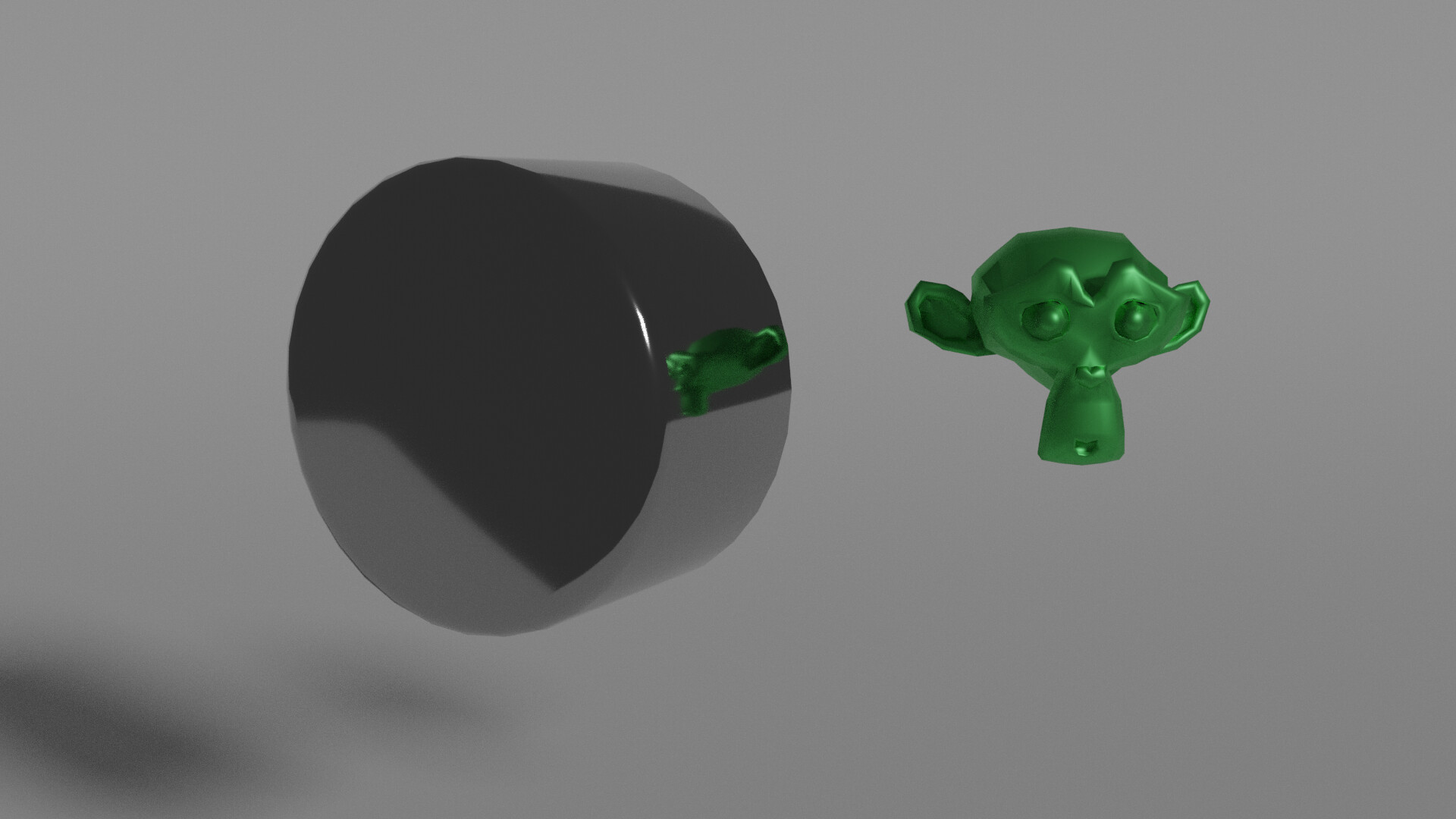
A warning; if at all possible, use and manipulate radial tangent directions instead of using UVs, as UVs are not smoothed across the seam. The left shows UV based tangents completely messing up everything (seam is up on the knob, see the sharp shading edge even if the pattern is seamless) but is easier to setup, and the middle one where I avoid the UV problem completely. The right shows the render in practice (Bechman influence is probably too strong, with too little roughness in the GGX, but still), see attached blend for several examples on how to get what you want.
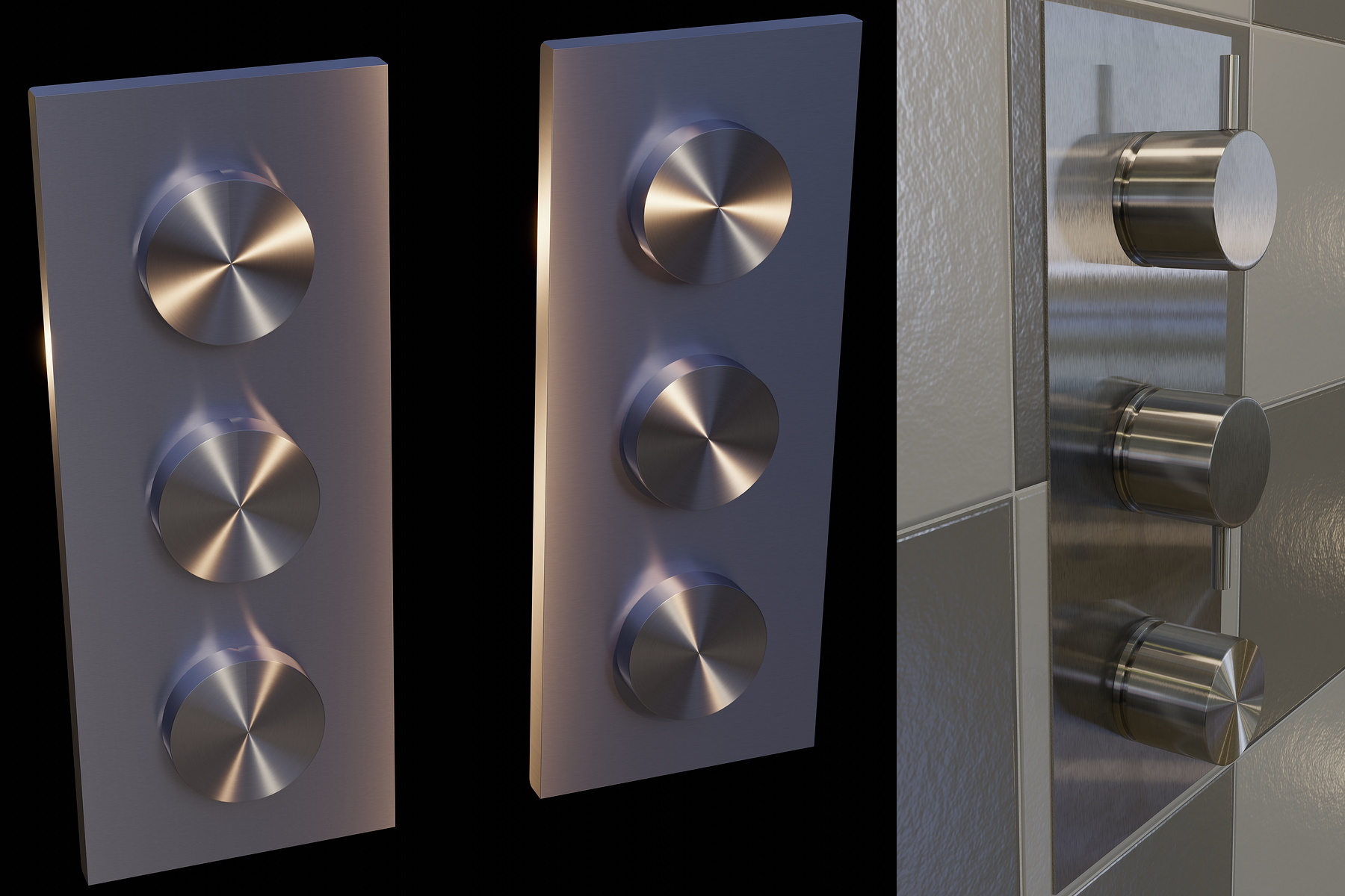
Aniso Knobs on Plate.blend (2.1 MB)
There are cases when you can’t avoid using UV based tangents; Utah teapot comes to mind as it has a bent pouring tube and handle that has to be UV based as no radial would match up.
3 Likes
I’m on 3.5 alpha.
That is the new “mix” node, it can mix floats, vectors and colour with a factaor (like the old colour mix node but with options to mix floats and vectors)
It could always mix those, but now it can expose the values going into the “color” without requiring additional nodes or clicking on the color to see its value. This version of the mix node is still missing from compositing nodes. But now I have, from the search menu, access to a mysterious “squeeze value” node that doesn’t seem to do anything. I’ve never heard of this node before in any context.
Strange - it’s not in the release notes for 3.5 either: https://wiki.blender.org/wiki/Reference/Release_Notes/3.5/Nodes_Physics
Yes I used to use the colour mix for vectors etc. Having the proper values as inputs is nice, also for int it will output value (fac instead of a colour).
I had not seen that one!
It looks like the squeeze node was in and then out, now in again. I got this with Google.
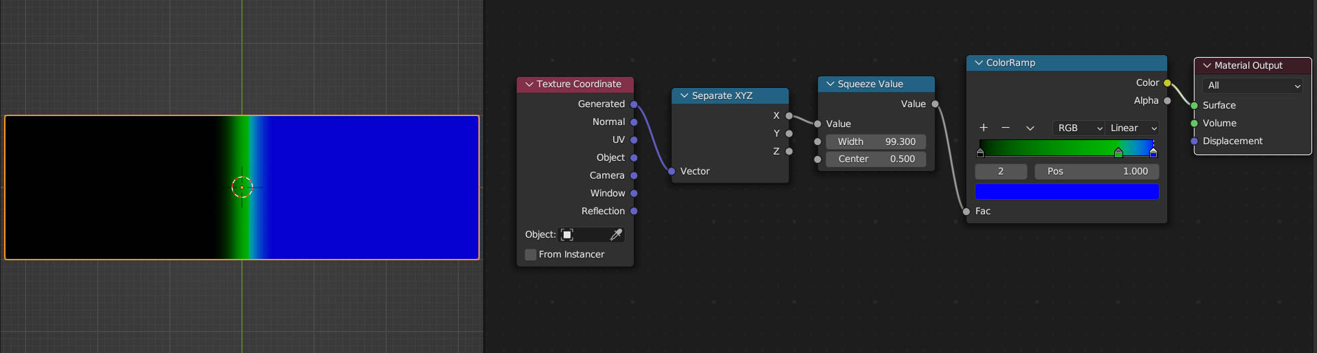
It does do something (squeeze and stretch values over a centre point). To me it seems that the width works the reverse of what I would expect. I am sure this is not the intended use case but you can see the effect:
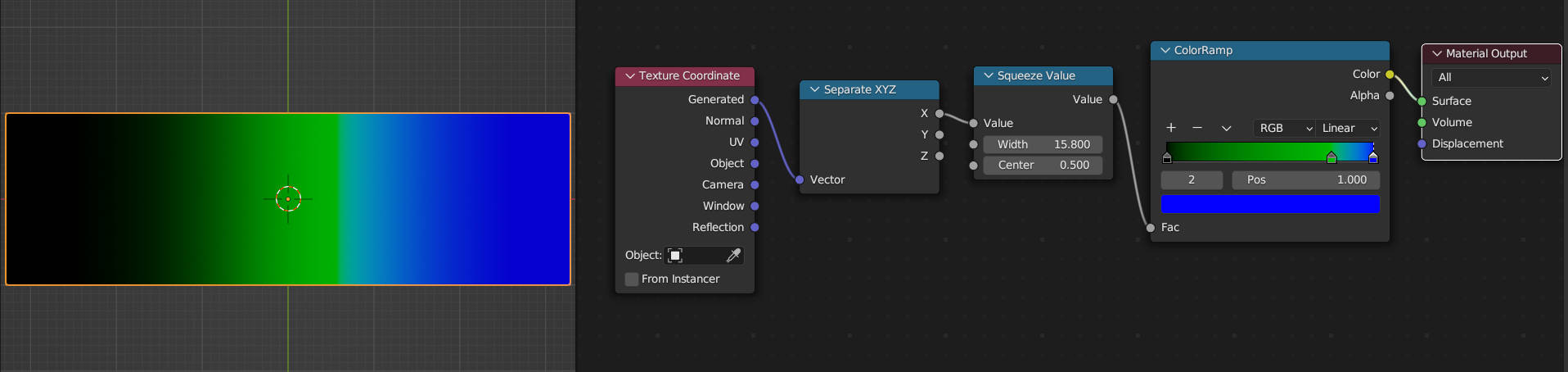
After Playing around with this a bit I have found that is is good for smoothing those infamous bump maps. ![]()
This almost looks corrugated!
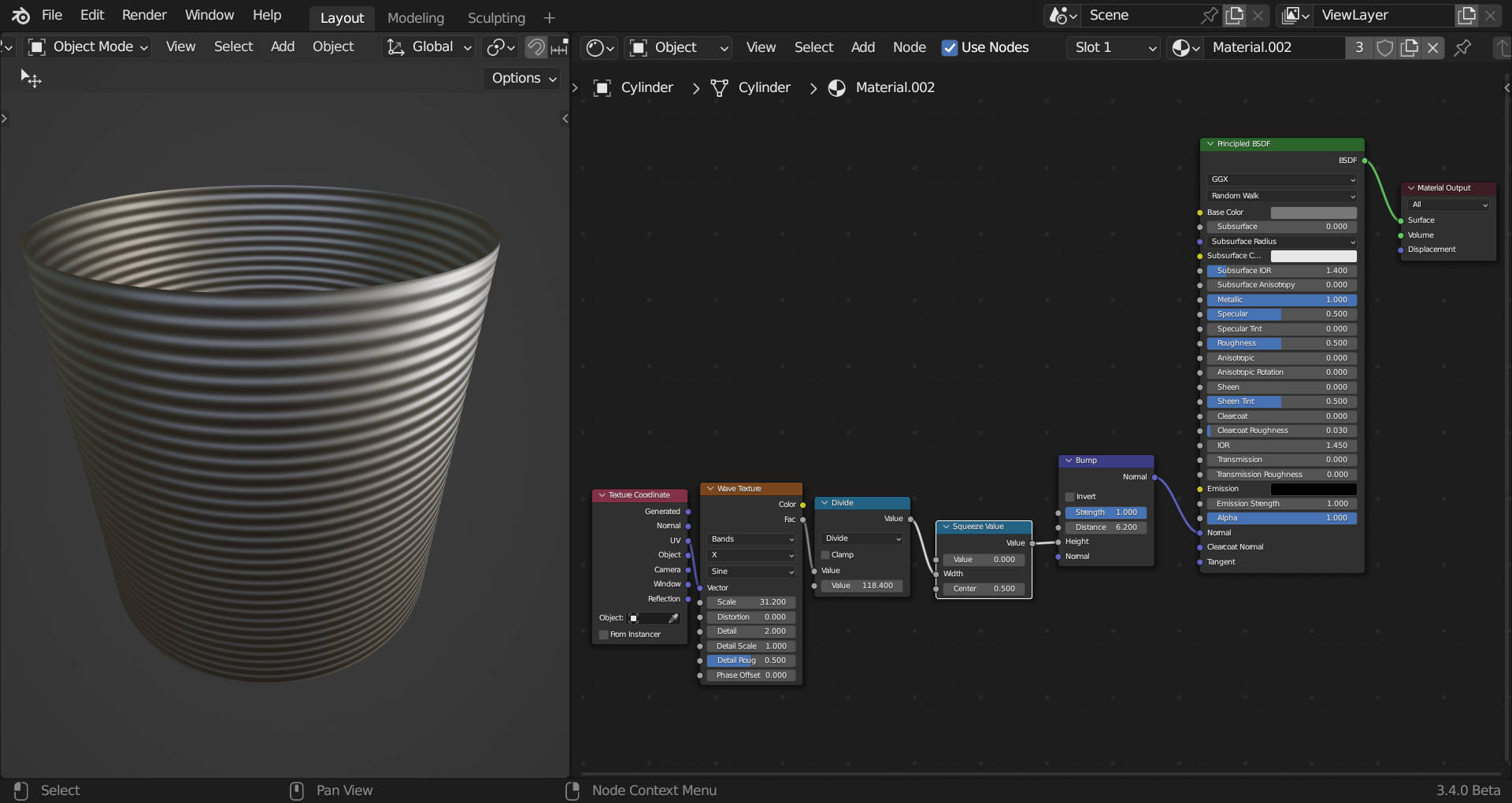
Ps Carl do not look at the bump strength and height values I know you will not like them. ![]()
Edit3!
I think that as I am dividing the width by 118.4 (pretty random to see what happens) the output values have a small range.
1 Like
After more tests you are right in Cycles the squeeze node does nothing, it only seems to work in Eevee.
Oh, I didn’t try high values. And also I only tried in Cycles. Looks to me like some sort of perlin gain & bias combined function. Which I have in my own math library but would be nice to have as I use them a lot.
LOL ![]()
1 Like