I am trying to model this atomizer for a perfume bottle and found that tissue add-on works very well to distribute a mesh evenly. However, I don’t know if it is even possible to control other aspects like adjusting position or using vertex for distribution.
Looking into this addon again ( thank you for this)… hmm there are no offsets possible… but…
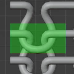
I think for this your repeative part should be only this one in the green area:
…this might give some problems at top or bottom row… maybe the Merge options can help with this (Bridge and Cup vertex groups… have to look for myself )
A good place to share is may be this:
…even if not started by the devloper @alessandrozompa … he entered the discussion…
there are also some other posts about it like for example:
Maybe even this could be interesting (using Geonodes but Tissue is mentioned):
Hi,
I’ll try to explain some options for achieving the desired pattern. I hope that it will be understandable.
First of all, by default Tissue will use the bounding box of your component and will match it with the target face. You don’t want that, you want to specify a different domain for the component, so that you can control the overlap between the parts. For that there are two alternative options, using the “Local Coordinates” of the component object, or the “Global Coordinates” (they works in a similar way, when using the Global you will need to place your object in the origin): https://docs.blender.org/manual/en/latest/addons/mesh/tissue.html#:~:text=Components%20Coordinates
This feature is used also in this tutorial: https://www.youtube.com/watch?v=PRIcB1Q-gK4&t=943s
The coordinates from 0 to 1 will match with the boundaries of the target face. If you want to keep some offset, make sure that the coordinates in that direction are smaller than 1. If they are bigger, then the component will overlap the neighbor faces (try to avoid that, that will not give accurate results for you)
When you do that, you will have extra options that allows you to clip your component:
So this is what I would do:
Model your component. And add an Array modifier in order to achieve the repetition in Y (just one copy should work for you. Make sure that its alignment in Local or Global coordinates match how you would like to apply it to the target face. Try to make sure that the green region goes from 0 to 1 in both X and Y
(you can chose between Local and Global, as you feel more confident)
Then use Clip, to automatically trim everything that is outside the green region.
You can then use the “Merge” option to merge together the different parts, and as final touch also “Dissolve Seams” in order to remove the extra edges resulting from the stitching option.
Let me know if it works. Of course any suggestion to improve or facilitate the process is appreciated.
Hi @usernew ,
the green region is something drawn by Okidoki, it’s not an option in Tissue. Even though I’m wondering if it may be useful to visualize
Anyway, it’s more an imaginary thing, which represent the coordinates space in Local or Global that goes from 0 to 1 in both X and Y. When you select a vertex in Edit-Mode, you can see what are its Local/Global coordinates:
If you use the Array modifier, make sure that you use an offset in Y equal to 1 as constant offset:
And then use the Local coordinates for the Component in the Tessellation together with the Clip option.
Yes, because the origin of your object is in the center. If you use Local coordinates, then the component will be trimmed along the origin and along the coordinate 1.
I find it useful to use this option:
Positioning and scaling the Origin in order to manipulate the alignment of the geometry with the local coordinates. Both position and scale matter:
Right now the component is applied on the faces of the object, with the normals of the face judging the orientation/direction. But this can be used for the vertices too if I am not msitaken.
In this the objects is using the normals of the faces of the sphere. But if we can control the rotation of the object to be constant using another object’s normal?
By default the normals are evaluated on the vertices, because this ensures a correct merging between the parts. It is possible to use different options, like Faces indeed:
In particular, if you use the Object method, then you can select a target object (not a direction object, as you described). This object should be topologically identical to the Base object (better to crete a copy of that). The tessellation will follow a direction that in every point of the base mesh connect the point with the correspondent point on the Target object.
You can see an example, the selected object (here as wireframe for clarity) is the Target: