How to make "scallops" or indents for fingers for gripping a handle

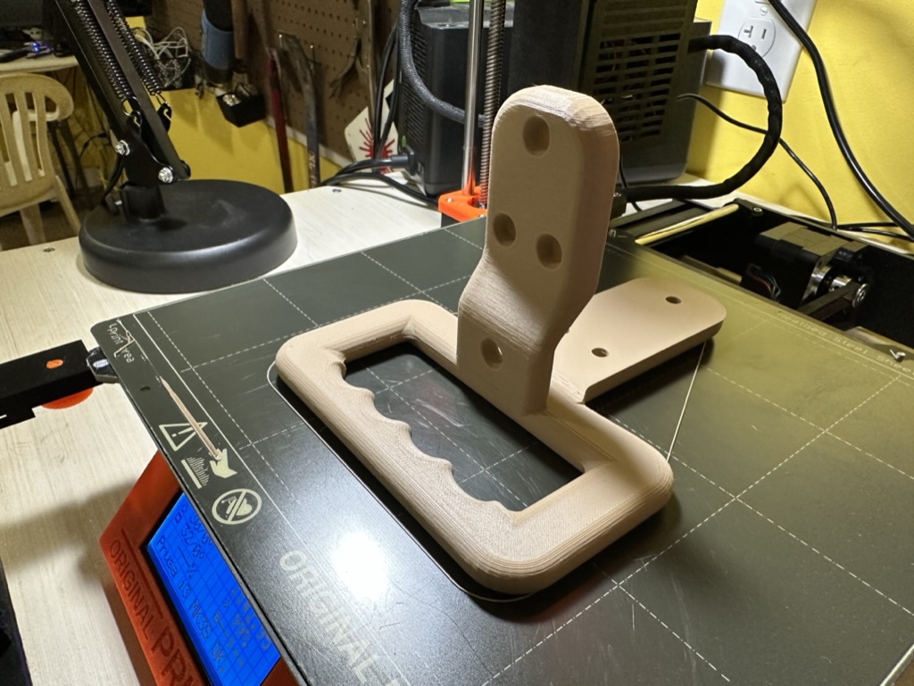
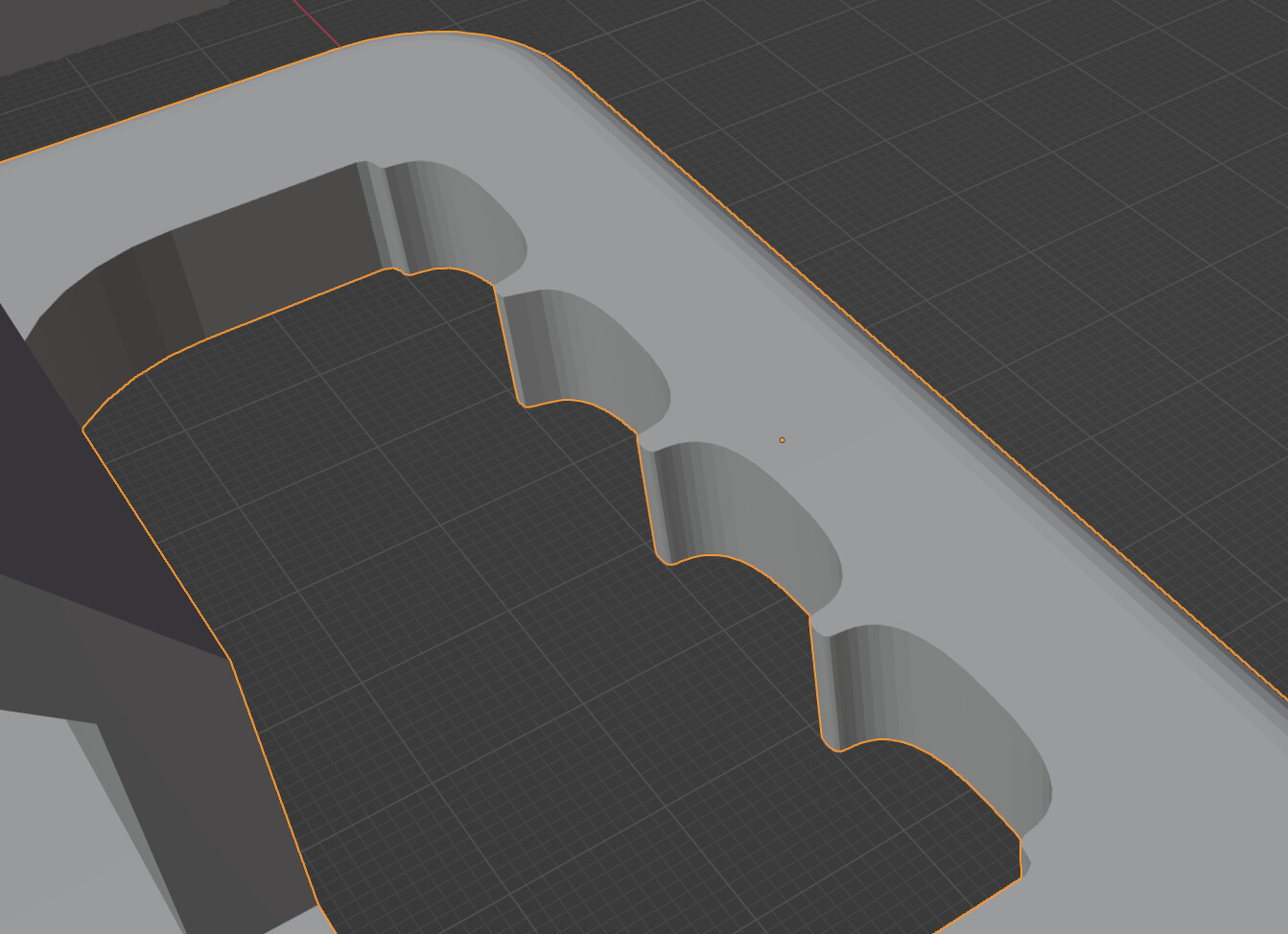
I have seen some handles printed by others that have a grip on them by scalloping out some indents for fingers. There are two sets of three of these kind of indents on the bottom of the top part of this handle:


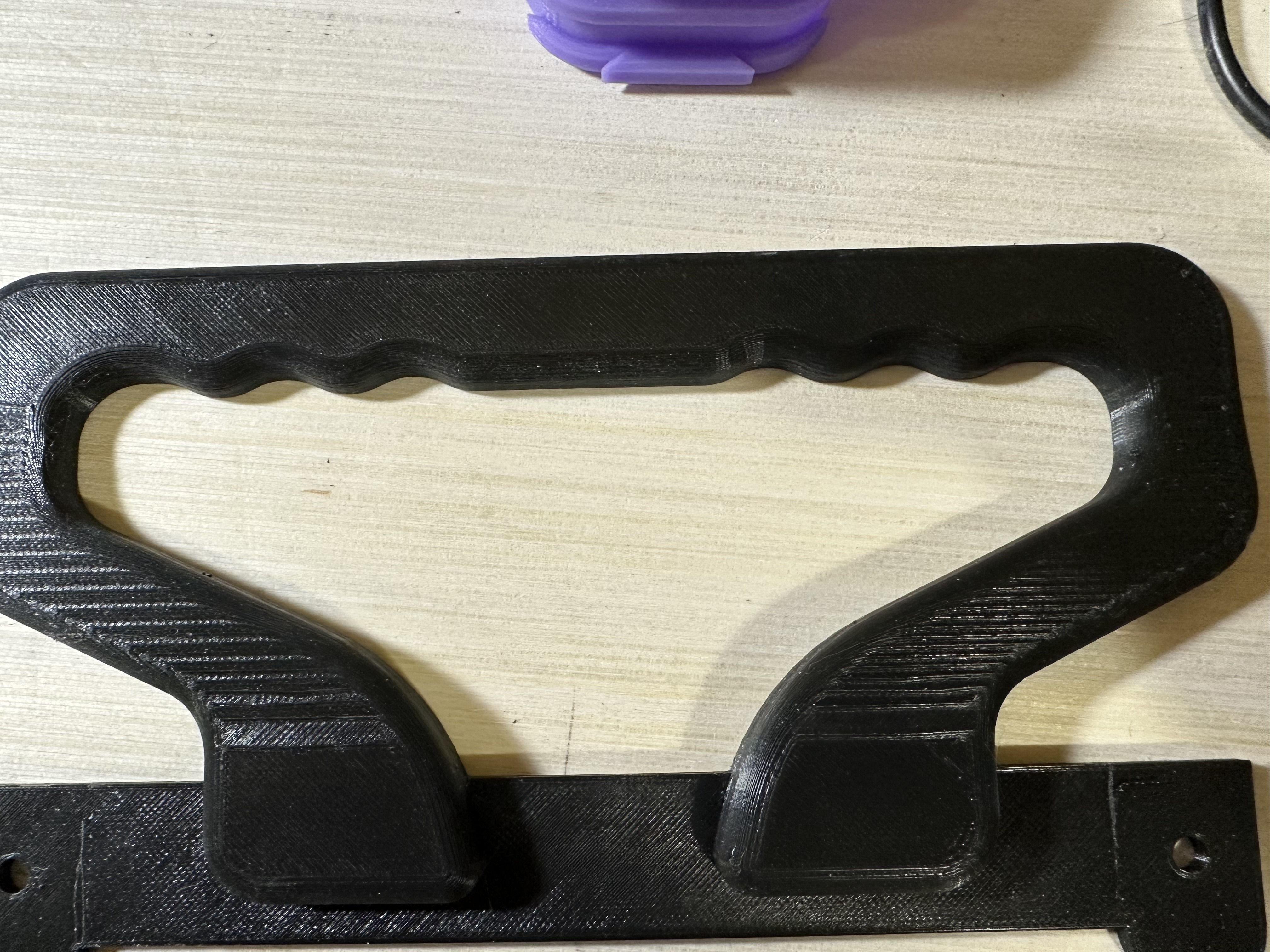
I’ve tried multiple methods to create a wavy or scalloped side to a solid like this. Originally I added indents, like described in this thread, and visible here:

I found it impossible to do a symmetrical bevel. I was able to do something close, after much experimentation, but I couldn’t get the effect I wanted.

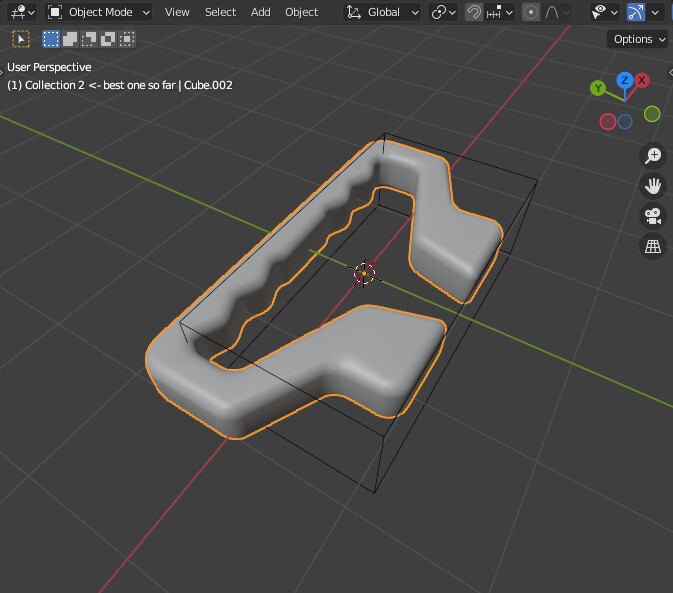
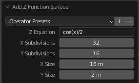
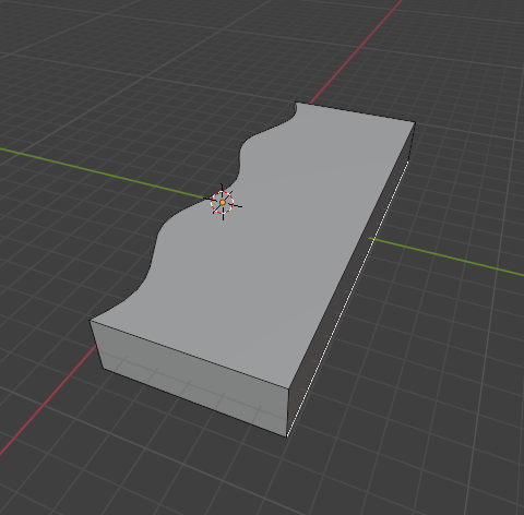
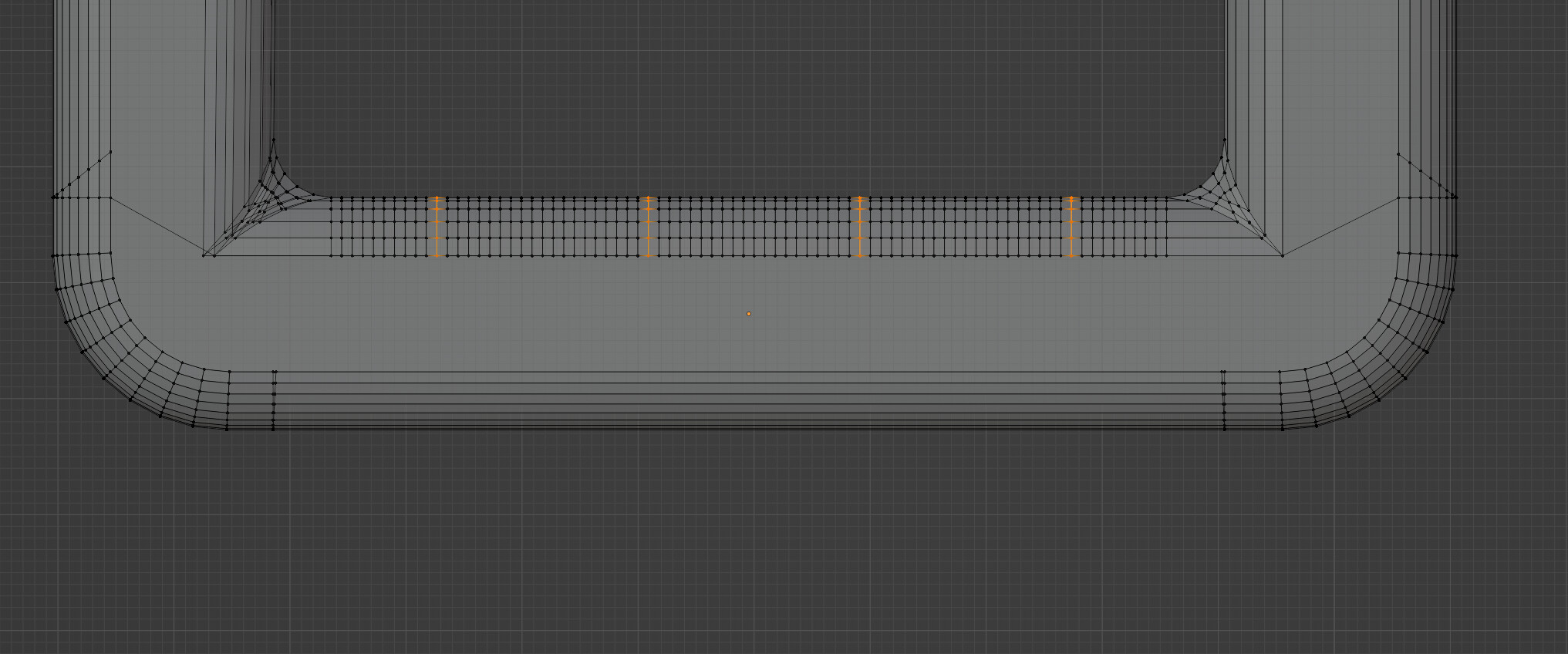
So I made a curve that gave me the outline of what I wanted, then used a shape as a scallop and got the indents:


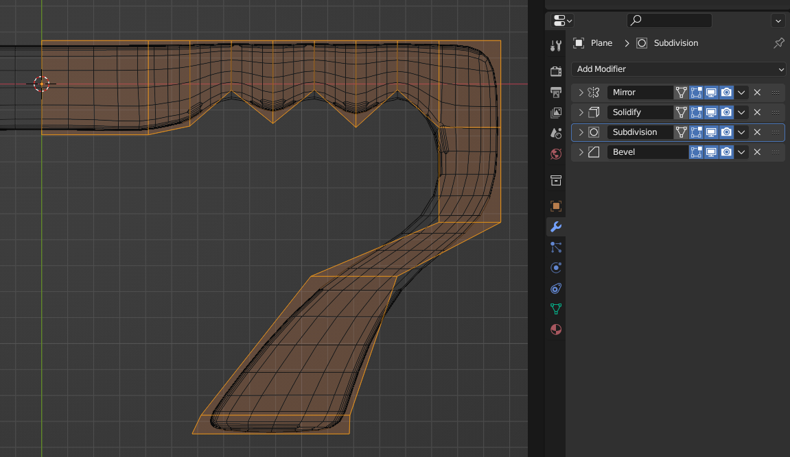
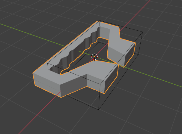
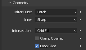
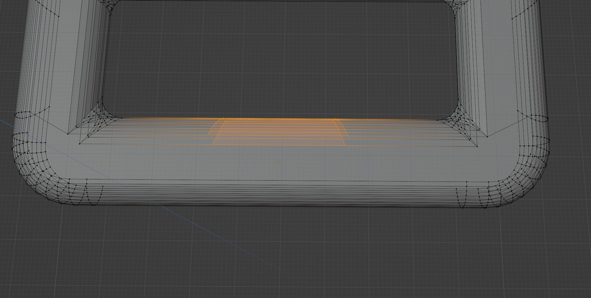
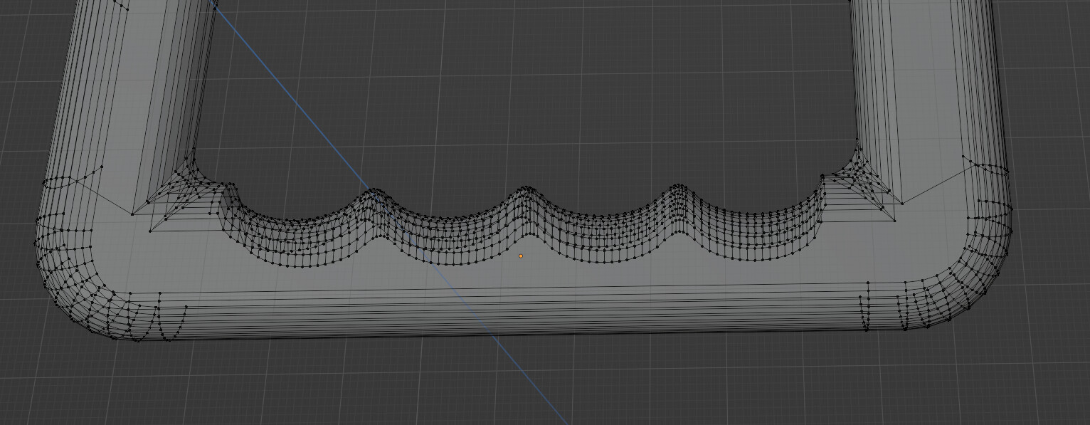
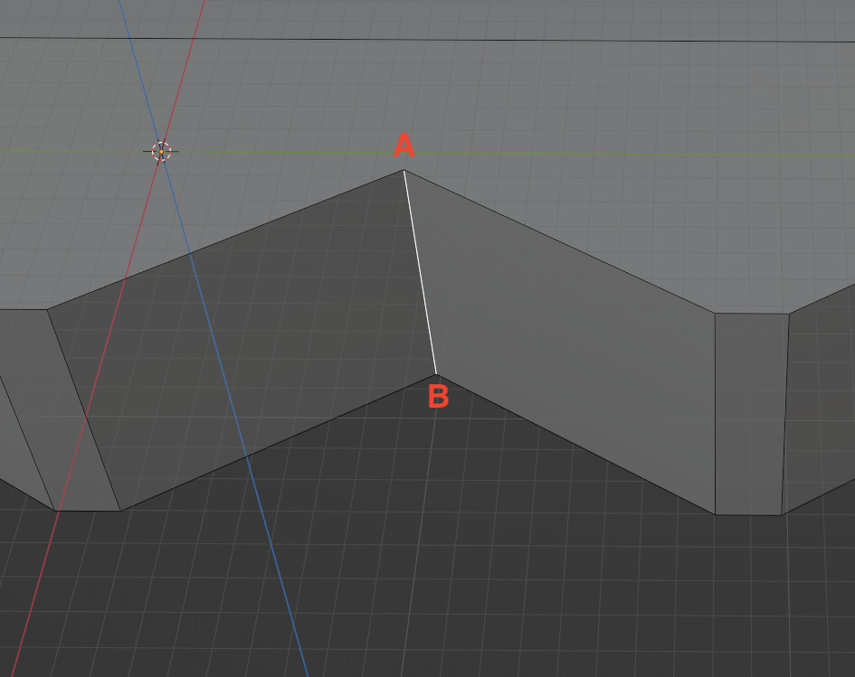
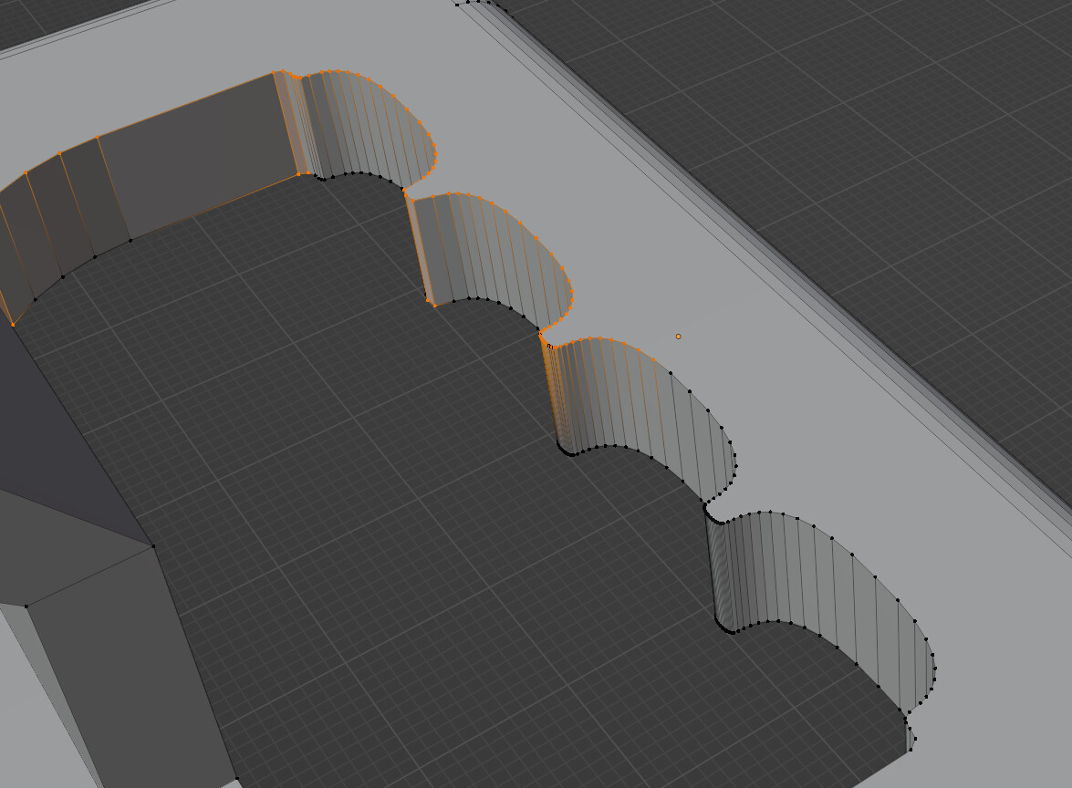
And I tried to bevel the top edge. Here’s a view of the selected vertices:

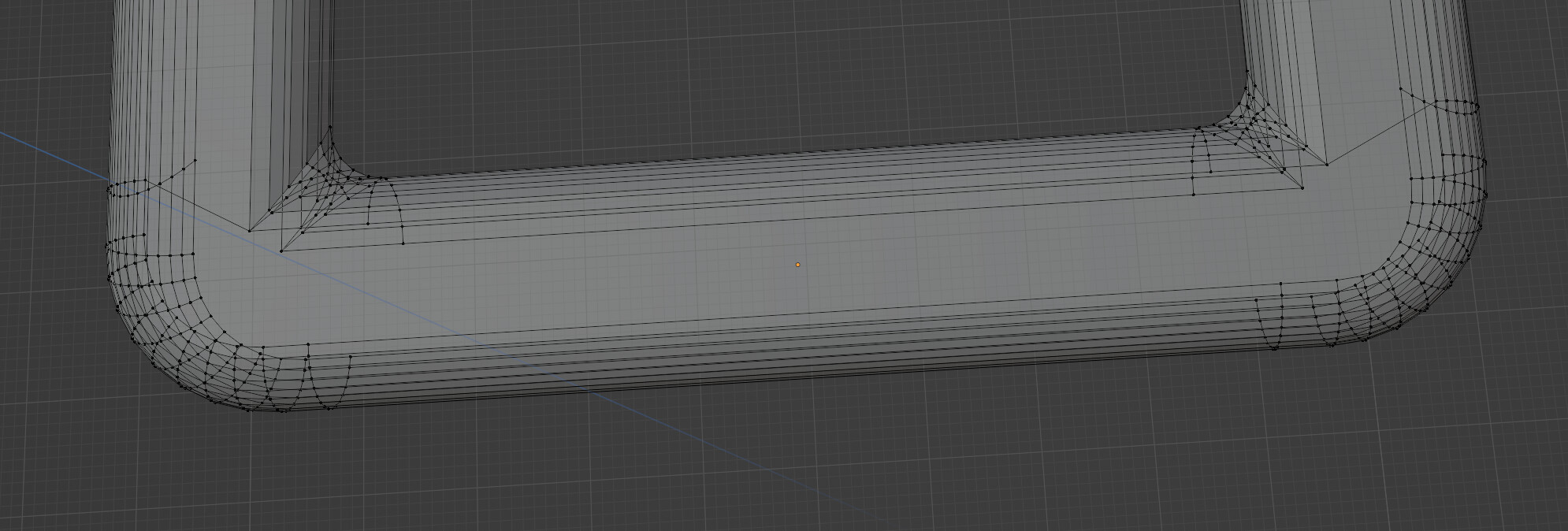
The problem (and I’m sure a lot of people are ahead of me on this) is that, on the points that stick out, the faces on those curves are thinner than needed for the bevels, so when I try to bevel that top line, I get a mess. (While the demo does not use that whole loop around the top inside, I’ve done the whole loop and get the same issue.)

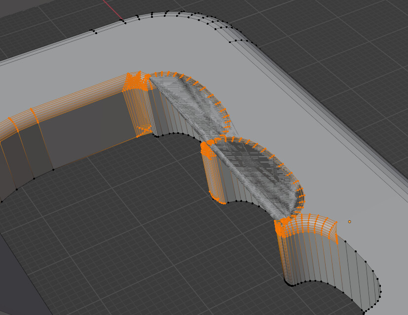
Not only do I get a mess within the original shape of the object, but I get those “ghost” surfaces cutting across the indents.

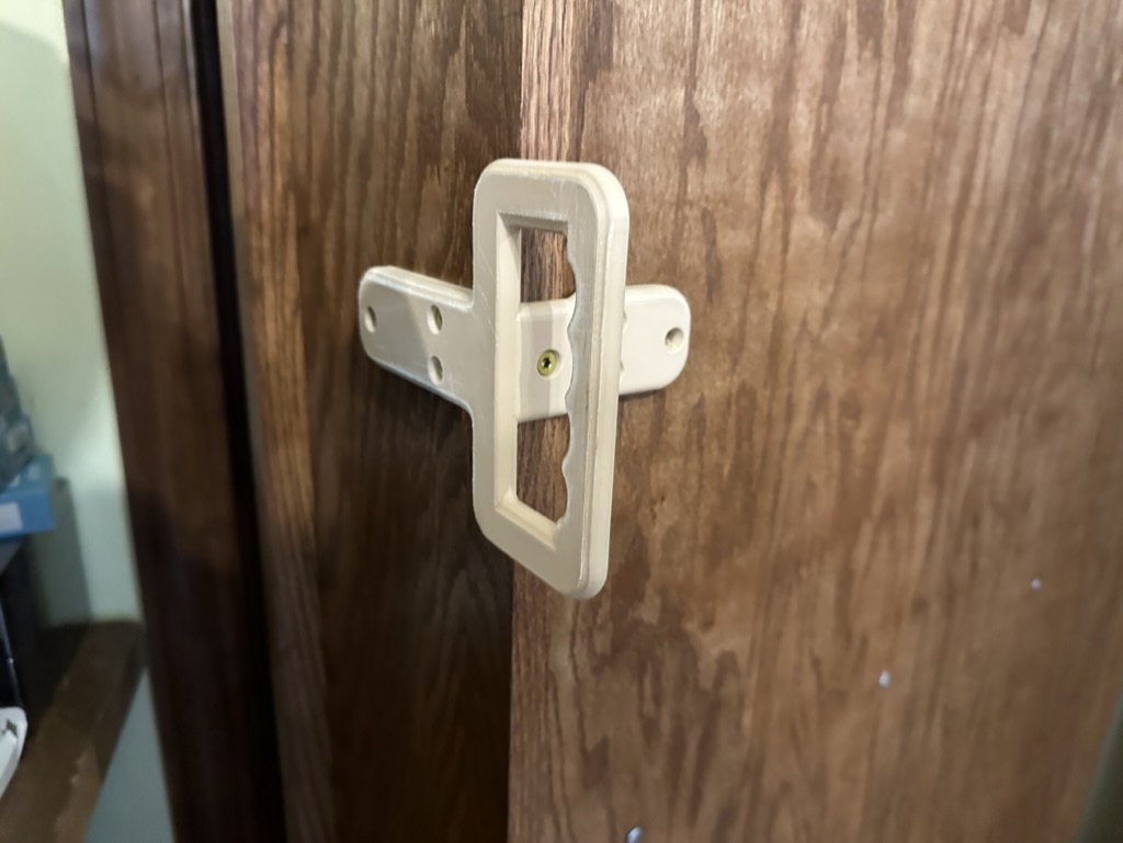
What else can I do to make these finger indents and to be able to add a bevel to them for comfort when I grab this handle and use it to pull some weight?

Hello,
your geometry is overlapping.
Maybe this addon could help you :

I was thinking any solution would have to prevent that. I tried different ways to do the bevels first, then do the indents and other ideas. I gave up on experimenting because I figured that was going to be the issue no matter what.

That looks like it’ll do what I need. I can’t test it until I get back to my study, but it looks good. Thank you!

Subsurface is your friend…
Just make the corners and subsurf till you are happy.

Just a plane with the minimum extrudes and edge loops added, mirror, depth, smooth & bevel.
Handle2

Let the modifiers do the work when its hard surface modeling. If its a character, THEN you stress and fret over every single point.
Learn the order you can use the modifiers. That knowledge itself is an important tool.
Once the handle looks good, save out as version 2, apply those modifiers then move on to the cross hatch pattern or whatever you add to the surface - nice landscape perhaps.
Save multiple versions and you can append from an earlier file if you need to. And you retain the base version with modifiers still active.
When you do a save as, there is a - and + sign in the file name entry box. Click the + to increase the version number by 1.

2 Likes

Hi. I tried one approach to make the handle based on the photo and here are the results:


.
.

The inner part of the handle was carved onto another one and then a bevel modifier was added. To make the dents even and closer to the reference I built a mesh starting from a cosine function
.
.

Here’s how it was done:
.
.
Addons used: Extra Objects (one of the default ones), Bool Tool

1- Create the handle without the inner part

2- Create a cos(x) function plane (addon extra objects → Math Function → Z Math Surface)
image

3- The one that I used is like cos(x) / x length = 5*pi, 32 segments on x, the rest as the default I think. You can tweak that to your liking
image

4- Rotate and scale to fit the handle. Use limited dissolve to reduce the number of redundant faces. Extrude it to make it solid and not just a surface…
image

5- This is one side of the handle. To make it two I moved it a bit and used the mirror modifier. Then applied the modifier and corrected the geometry (which had errors like wrong face orientation and an extra face inside the mesh at the junction)

6- You can move the vertices around and extrude them to make the rest of the shape
image

7- Then on the Bool Tool panel use the difference modifier. It might work or not at first. If not try to look for faces overlapping or geometry inside on of the meshes
image

8- Now put a bevel modifier and uncheck the “clamp overlap” option at the Geometry tab inside the modifier

9- It might leave some shading artifacts. To reduce them on the same tab I changed Miter Outer to Patch. It worked on some corners
image

10- Another Bevel modifier was added just to correct some of the corners, but wasn’t strictly necessary
.
.
I hope it helps o/

Here’s the blend file as well:
20230401 handle test.blend (1.1 MB)

1 Like

A lot of information in just a few replies and I’m still processing a lot of it, so I’ll be making other replies in the next day or two.

I want to add that I’ve tagged this as 3D printing. I thought the comment at the end of my post about “when I grab this handle and use it to pull some weight” also indicated it was for a real world object I was making, but now, looking back, I realize that’s not really that clear. That’s my mistake.

@Matakani , sorry I wasn’t clearer. Like I said, that’s on me. But it looks like subsurface won’t work for what I’m doing. (I had to look it up.) I am making something to print, which means exporting it to an STL file and slicing it. The mesh is goign to have to be the actual shape. I may be misunderstanding this, but it looks to me like subsurface will work for rendering, but not for printing. Am I wrong and does subsurface change the mesh so it’d show up for a slicer reading an STL file and looking only at the mesh?

As I said - Use the Subsurface to make it - then apply it. Then tweak the thickness.
Look close at my first image - the selected orange mesh, and compare it to what the subdivison modifier has done (the dark mesh) to that oh so basic mesh. 28 Vertices - with 4 modifiers. You have about the same number on the top edge of one of the finger indents.
Keep It Simple Sir - KISS. :nerd_face:
Learning to use minimal vertices is one of the hardest parts of 3D. It took me years - back before You Tube existed.
Wavy Edge
Several seconds - No boolean needed. :man_shrugging:

4 Likes

I’ve found that sometimes boolean modifiers create more problems than they solve. With 3D printing, when I’ve been working with threads and making the male and female parts, booleans take any problems with one part and compound them in the other. They’re quite useful, but I’m learning that when I can do it another way without a lot of problems, I avoid it.

Also, with simplicity - yes, I prefer simpler. I’ve found a number of cases where n-gons are actually useful in printing instead of breaking a face down into triangles or quads.

I’m not clear what you mean by the subsurface mod. The only thing I found when I searched for “Blender subsurface” was subsurface scatter. When I look in the modifiers to find one to apply, I don’t find any “subsurface.” I do find "subdivision surface and it looks, in your first comment above, that’s what you’re using.

I also see how, in your second comment, you are creating the sine wave shape and curving it - which helps, since I did get the first few steps of that done, but then was using bevel and that wouldn’t curve them appropriately. But once that’s done, and the finger indents are there, I still have the issue that I need to bevel the edges.

It looks like, in your first post, you’ve beveled the edges first, THEN are applying the subsurface mod you’re talking about. Is that right?

Yes Subsurface means Subdivision Surface. Its combining the words… Old school blender head…

Remember I am working with a plane to keep it as simple as possible.
Look at the modifier order in my first comment. Top of the modifier stack gets actioned first. So bevel is last. Rearranging these breaks the whole thing.
Mirror - to do half the work.
Solidify - to make it thick enough.
Subdivision - to smooth all the corners.
Bevel - Obvious…
Keep in mind with the Bevel Modifier that you can use Vertex Groups (Under Limit Method) to delimit the Bevel. So select the wavy finger grip area and give it a weight (in the vertex group) of 100. Then invert the selection and give a weight of 50. Weight meaning adjust the slider underneath the Vertex Weight list and press assign. Then the different areas get different sized Bevels. You can do the same thing with the solidify modifier to make the various parts of the handle have differing thickness.
You can also use Weight Paint Mode to set the vertex group weights - the gradient tool is useful for this.

Keep asking… Happy to supply more ugly screen captures if it will help… :smiley:

1 Like

@Matakani:

I’ve been going through your method a few times when I saw something else about proportional editing, and it turned out that did what I needed in a few steps. More below.

@Livia_Soledade:

I didn’t reply, but I did look over your solution. I went for the other one first because I’ve had troubles in 3D printing with bool tool and boolean modifiers. I know it usually works, but I’ve had problems with errors that get compounded if I have to use boolean modifiers in several stages. As I mentioned above, I found another solution that worked rather easily.

What I did:

I used the example given as only an example, since I couldn’t easily find the shape with the finger indents in anything else. I’m doing something a little different that is a handle for the back of a special door. (The door to my study is a hidden door that looks like a bookcase, so it has books and other things on it and is notably heavier than a normal door. I need a handle to go on the back of it so I can easily pull it open from inside the room. (That’s why I wanted a comfy grip - it’s used to pull that heavy door open.)

I did all the beveling on my handle first:


The handle goes on the inside, on the nearest part. Once I did these bevels, I added 2 edge loops on just the inside bevel:

Because of the corners being beveled as well, the edge loops were not perpendicular to the edges in the bevel, so, on each edge loop, I selected all the vertices, pressed S for scale, then X (due to the orientation of this piece), then 0, so it scaled that edge loop to a flat line perpendicular to the bevels.

From there, I moved the two edge loops to next to the corners. I used Snap to Vertex so they’d both align with the part of the bevel innermost on that edge:

That was the hard part. If I didn’t do that, then the edge loops I create for doing the main work would have had alignment issues and the resulting surfaces would be jagged. Then I added 78 edge loops. (The number was related to the size of the area I was working with and the finger count. 4 fingers, so 20 per finger. More edge loops meant more counting.)

From there, I selected 4 edge loops, evenly spaced out along that side:

Then I turned on proportional editing, used G-Y to grab the selected edge loops and move them on the Y axis:

From there, I added some edge loops on the parts between the fingers and did some more proportional editing:

I know it’s using more vertices, but once I realized proportional editing might help, it only took me a minute or two to test it, then, from there to doing the work was easy and quick.

2 Likes

Just in case anyone is curious, here’s the printed version. It has two surfaces at a 90° angle so I could fasten it to the side and back of the bookshelf door. Here it is freshly printed:

And on the door:

Wider view for context:

1 Like