I'm trying to project the outline of an object onto a 2D plane

Hi all

My 1st post here. I’m a bit of a Blender noob, but been using CAD for 20 years. So still getting my head around the slight differences :slight_smile:

I want to get the outline of an object onto a 2D plane. Then (ideally) measure the area of that outline. I can do this in CAD from a DXF if neccesary.

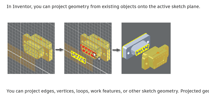
In Inventor, there’s a Project Geometry button that does this. I use it all the time.

So, can I achieve the same workflow in Blender somehow?

Thanks folks

Hi and welcome to the forum.

As you want to maintain the original mesh, you would have to copy the faces you want to project and separate the copied faces from the original object (you do not have to separate them but I probably would to be able to hide the projection easily).

Then you can scale the copied faces to 0 on the preferred axis, press S-Y-0 to flatten them on the y axis and move them to where you want G-Y to move on the Y axis).

You could also use the shrink-wrap modifier but that would require and actual Plane to project onto.

I do not think there is a "one click solution for this (there maybe an addon I do not know of)

For measurements check out the “measureIt” addon that is included in Blender. It works well but is a little fiddly to get used to, there are many tuts for it.

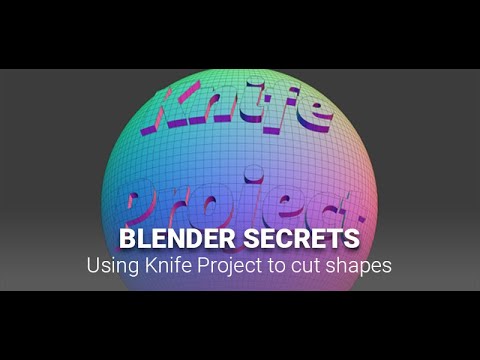
There is- knife project:

1 Like

I do not think that is what the OP describes. Sort of the opposite.

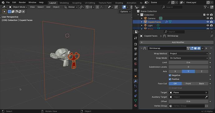
This would be the shrink wrap method:

I set the plane to viewport visibility - bounds and turned it off in render.
Duplicated the faces the faces and separated them from the original, then shrinkwraped them to the plane.

This might work, depending on how Inventor does it. The only issue might arise when he needs to achieve "Then (ideally) measure the area of that outline. " This calculation might end up becoming wrong if the shrinkwrap projection does not necessarily reflect the actual plane projection.

Also if the OP needs this regularly, probably it is a good idea to create a geometry nodes setup, that way they won’t need to deal with mesh duplication.

1 Like

Good idea a geometry node “tool” could probably work.

Hey thanks a lot for the quick replies.

You’re right @DNorman , ‘knife project’ is the opposite of what I want. (Useful to know though. In Inventor there’s a ‘emboss’ command that does that)

I will have a good try with the methods you suggest. And play more with the measure tool.

I struggle with anything node based though :smiley:

They take a bit to get used to but are really fascinating and addictive once you do!

As I am already addicted I made a geonode modifier to do this, I sometimes do technical drawings so It will be useful to me too.

I tried a geonode “tool” version but it was too frustrating because tools are destructive and that is not good. In the end I settled for the modifier.

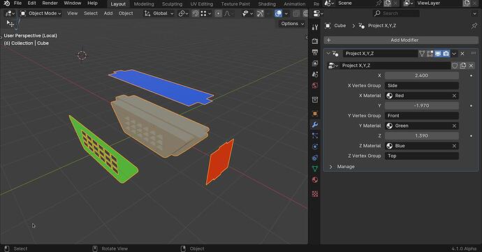
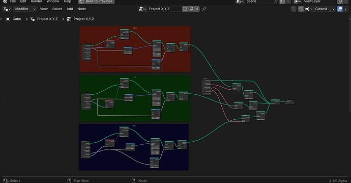
This is what it looks like. It works with vertex groups. You make a vertex group and assign the faces you want project to it.

There are inputs for the 3 main axis’s, so you can make 3 vertex groups.
You can also assign a material to each projection.

When an axis is set to 0.0000 there is no projection, as soon as you slide that value there is projection on that axis

Here is the file, you can just append the geonode group and use it on any object. You will need 3.6 up to open it;

Project X,Y,Z.blend (180.7 KB)

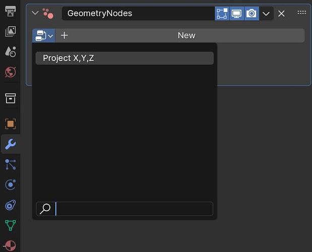
Append the node group ( called “Project X,Y,Z” ) add a geonode modifier to your object and then select the “project x,y,z” in the modifiers drop down menu.

Remember to set the vertex groups, I set the default group names to Group, Group.001 and Group.002 but you will have to create those groups in your object and assign vertexes to them.

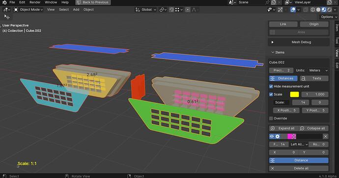
As for the area measurement “MeasureIt” does it fine, but bare in mind that it measures the area of the selected faces. So if your projection has holes it does not count them. Also you have to apply the geonode modifier to measure the projection.

When you open the file if you enable the MeasureIt add-on and in the options in the view menu hit “show” you will see the measurements.

I have given the measurements different colours in the MeasureIt options.

On the right the pink measurement 0.61 square meters is the measurement of the inset faces (the holes)

On the left the light Blue measurement on the left is the area of just the projected faces. 1.87 Square meters

On the left the yellow measurement is the total of the front faces + the holes, 2.48 square meters (0.61 + 1.87)

Hopefully this will make you more curious about nodes :rofl:

I even arranged them up so they are more readable :smiley:

Edit
I have updated the file, I got rid of a seperate geometry node in each axis as it is not needed.

I left the merge by distance as it will get rid of faces in the projection that are perpendicular to the projection. For example if you make a vertex group of the front faces and the faces at the bottom of the holes the projection also projects the sides of the holes (because they share the vertexes). The merge by distance will get rid of the double verts that this creates.

3 Likes

Woah, you have been busy there!

Thanks a lot, there’s a lot for me to chew over there. I’ll try and try your file tonight.

1 Like

I have edited the file a bit and updated it getting rid of three nodes. (see the edit in the post.)

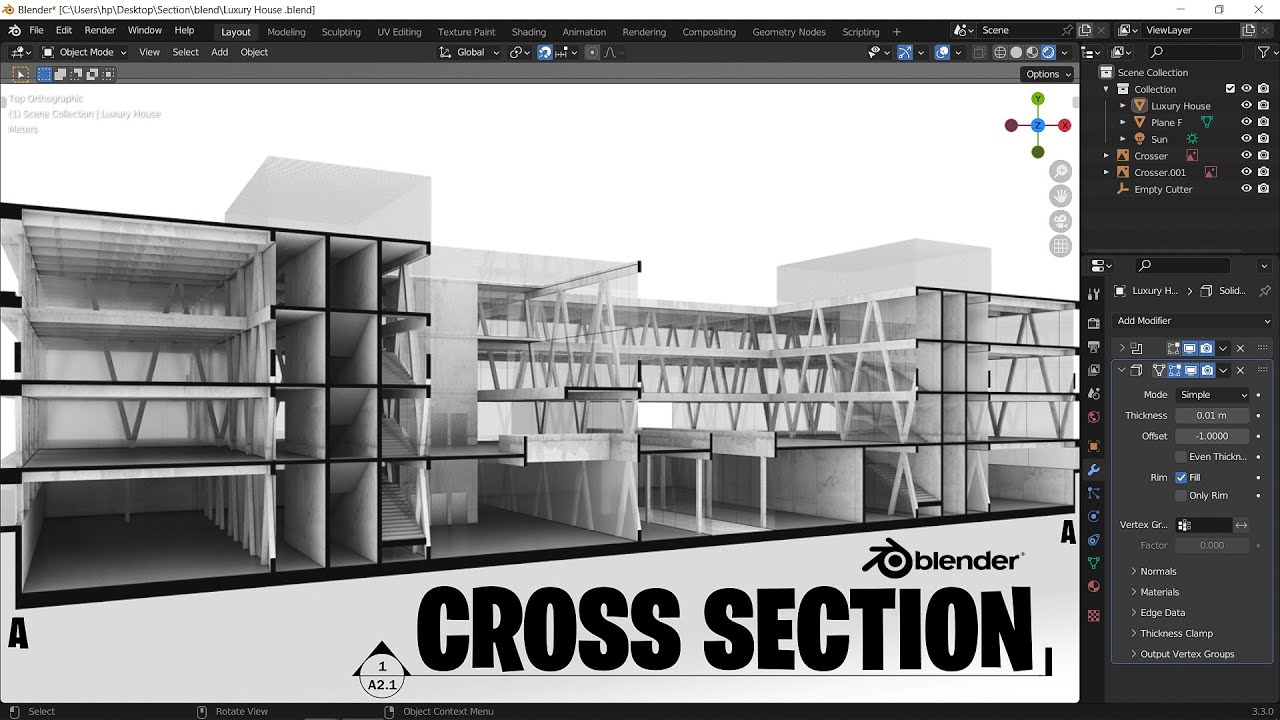
Here are a few ways via procedural transparency, camera clipping and Booleans…

There is another tutorial on cross-sections.

and an add-on…

or…