Metalness vs. Specularity

I was today years old when I learned that the Metallic and Specular values on a Principled BSDF shader are mutually exclusive.

I picked it up from this video: Exercise 028 Principled BSDF Shader. The full quote is:

It’s worth mentioning that in Blender the Principled BSDF uses a metalness workflow where the Specular and Metallic inputs are mutually exclusive, so if you set the Metallic input to 1 it will assume that the material is 100% metal and will ignore the Specular and Specular Tint inputs.

Meaning if I set the Metallic value to 1, the Specular value is not used at all.

I’m going to assume that the pros out there knew this already, but this was news to me, and I’ve spent the last few years reading anything and everything I could find about PBR metals in Blender.

Obviously, I either missed this information, or it was over my head at the time I encountered it.

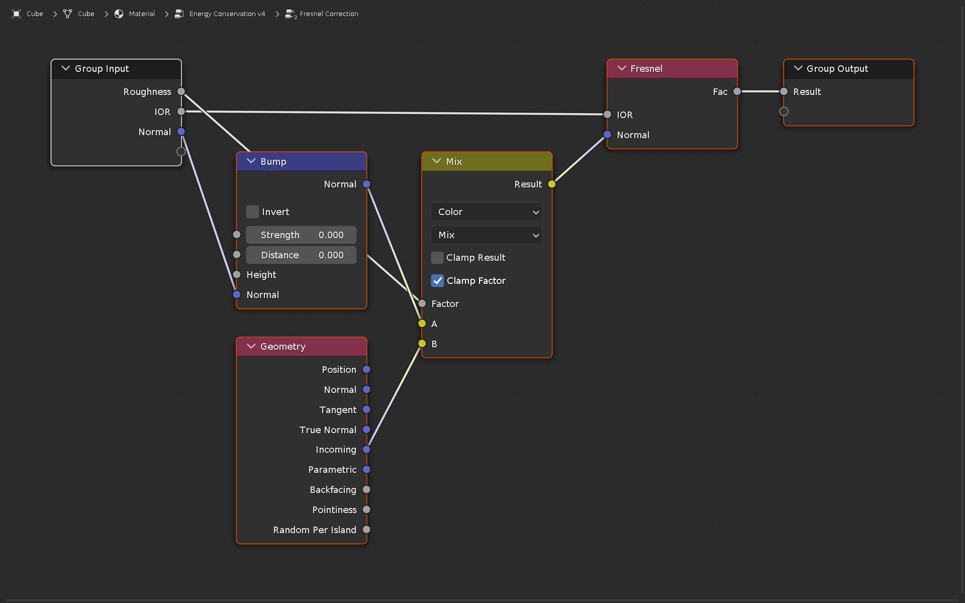
This news makes the IOR to Specular conversion node I’ve been using on my metal materials irrelevant. Ooof.

Workflows

I did some Googling which brought me back to this video I’d seen before but only partly grokked at the time: Specular vs Metalness Workflows for PBR Shading in Blender.

It describes the workflows for the two types of materials as:

  • Metal workflow
    Color + Microsurface + Metallic

  • Specular workflow
    Color + Microsurface + Specular

(I presume that Dielectric materials use the Specular workflow.)

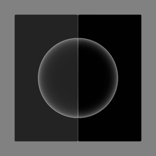
So it makes sense that a Metallic value of 1 would override and “turn off” the Specular effect.

Metallic values less than 1.0?

The Exercise 028 video also served up another interesting morsel:

Some examples of materials based on the metal finishes and their approximate metallic values: mild steel 0.05; rebar steel 0.05; structural steel 0.05; 304 stainless steel zero and 316 stainless steel 0.8; 3003 aluminum 0.9; copper 0.9; gold 0.9; silver 0.9; platinum 0.9.

He later offers a suggested Specular value of 0.5 for Chrome, which seems to contradict his point that metals have no specular value, but maybe Chrome is a “finish” and not a metal? My brain is starting to hurt.

In any case, the rule I’d been trained to follow was that Metallic is either 0 or 1, unless you’re getting into NPR stuff.

But I’ve been working on a Cinnabar material, and it doesn’t look quite right unless I introduce a little bit of Metallic. And I’ve been feeling like I was cheating somehow.

But now… I think I have some exploring to do.

I mean, I note that he’s talking about “metal finishes”, so I’m going to have to do some more digging to understand if and how this differs from good old-fashioned “regular metals”, but you can bet your sweet bippy I’m going to put those numbers in the Metallic field and see what kind of Gold and Aluminium and etcetera I get.

Any feedback to confirm, deny, amend, expand or correct any of this is very welcom.

2 Likes

It’s best to keep metalness being either 0 or 1, since the surface will react very differently depending on that.

But say you want to do a metal material covered with dust, it can make sense to lower metalness where there is dust. Or probably to recreate material like this :


Having more or less metalness can help.

Yeah you shouldn’t be enslaved by the tools, the end goal is to have a good image no matter what.
It’s important to understand the theory, so you have a good basis, because sometime things can end up looking weird because you used parameters that are irrelevant to the material you’re doing.
In the other hand we are not scientist modeling light interactions.

To make an accurate material you need to gather a lot of data, and make sure they are translated correctly into blender. You also need to do a correct environment so they are lit correctly too.
That might even not look good because reality while being accurate tends to be boring too.
So a good balance is needed between accuracy and the final result. Unless you value accuracy over visual quality.

In general I start with a base that makes sense and I don’t hesitate to eyeball stuff later to add the finishing touches.
Just like these food photographer do : https://www.youtube.com/watch?v=9k7PJoNAXkk

Also when working on big projects like a movie or video game, sticking to PBR rules helps to have assets that reacts well under different lighting scenarios, you also have more chances that each assets made by different people ends up working together.

When you work alone, and say for one object under one lighting condition, then you have less to worry.
Lastly, these video series helped me a lot when I learned about PBR :

It’s a bit outdated since now we have the principled BSDF, but the overall theory is the same !

Have fun !

2 Likes

Specular value is still used with full metalness, although specular tint appears to be ignored. You can be sloppy and rely on specular to add white specular towards the edges, or you can do it properly and set specular to 0 and control edge tint via some angle based control affecting the base color. Either way, the effect is subtle and not what is going to make or break the result.

Chrome is not a finish, but a metal; chromium (Cr) with atomic number 24. While it is typically applied as a plating, that is the end result you see.

Specular workflow is the only way to achieve some very special dielectrics (with tinted reflections which normally don’t happen), but what is used is generally up to the engine. Metalness require less data stored in images as the metallic channel is grayscale, whereas specular require a separate RGB image to define the specular color.

“Approximate metallic values” - just ignore these, they make no sense at all. Use metallic 1. Unless they have an oxide layer, in which case you’ll just have to judge by what you observe - don’t be a number slave. Cinnabar I have no idea about, but if you feel you need to introduce some metalness against all common sense, then do it. If I had to make some sort of silvery fabric I might just end up trying it myself - obviously the linked jacket isn’t made up of pure metal, it just looks like it.

As far as metals go, they will very often have an anisotropic look due to toolmarks from machining or abrasive polishing processes that tends to go in a specific direction.

3 Likes

chatoyancy

Blenderguru / poliigon had a video talking about how they scan real wood to make materials and apparently the only way to capture chatoyancy is with the metalness, so I think there is a real world reason to have metalness set to something between 0 and 1.

Well, it more the solution they found to solve that particular problem, but that doesn’t mean it’s the proper way.
But whatever works ! It’s just that by activating unrelated parameter you might end up with something looking a bit weird.

Principled BSDF is the port into blender of the Disney principled which is meant to be physically plausible and at the same time allows for artistic controls. So it allows to bend the rules for sure !

Great feedback!

Sozap, that plastic sword material is beautiful. And thanks CarlG for clarifying that Chrome finishing/plating is still 1.0 Metalness.

Honestly, I’ve made a nearly full-time vocation of studying Blender and related 3D topics for the last several years, but I’m constantly finding new information that sends me down rabbit holes that would require a master’s degree to fully grok.

I thought I’d exhausted YT for PBRs, but the CynicalCat videos were new to me. I watched a couple of them through the Metal workflow, and picked up a bunch of tips.

Like factoring the roughness into the fresnel. Makes sense.

IDK if Blender has rectified the Fresnel issues in the seven years since the video above was first posted, but I followed CC’s lead and made a Fresnel Correction group which I added to my Energy Conservation group.

I also grabbed their sample materials from Gumroad, and they still work in version 3.4 and look great.

Corrected fresnel

For reference, here’s the basic Fresnel node at work:

And here’s CynicalCat’s corrected setup:

Of course, the visible difference may not be tremendous on rendered materials, but still…

The node groups

So here’s CC’s basic Fresnel Correction group:

Here it is inside the Energy Conservation group I’ve been working on for a while:

For the specular highlight color I’m using white at HSL 0/0/0.99 for Metals, and for Dielectrics, I lower the HSV Value of the Base Color to 0.01.

And here’s the group plugged into a Principled BSDF to make a bright blue metal shader:

I’ve heard tell there’s a new version of the Principled BSDF on its way, which will likely make my Energy Conservation group irrelevant. But even so, what I’ve learned working on it has made it a worthwhile effort.

In the meantime, I’m going to keep playing with my Cinnabar material, and hope I eventually get it to look almost as good as Sozap’s plastic sword.

1 Like

Ah, sorry didn’t read your post above in full. You are already aware of Principled V2.

I’ve been interested your Quick Metal Materials for some time, and have regularly downloaded the updates. Several times in a current project I’ve swapped out a particular metal material for the updated version. I didn’t know anything about energy conservation, and when you began including the energy conservation setups, I just assumed they were more technically correct and would yield better results.
Recently I came across the video below, and figured I could use some more insight about this energy conservation stuff. What it states, to the best of my understanding, is that these compensations are only really applicable to dialectric materials and metals with clearcoat. And that with fully metallic materials w/o clearcoat, Principled BSDF already handles the energy conservation correctly. Not positive than I understood correctly, I messaged the video creator, and he confirmed that this was indeed the case.
So now I’m somewhat confused as to why the QMMs have energy conserving nodes. I may be misunderstanding how they work though, and was hoping you could provide some more insight.

1 Like

Nice – thanks for this information!

I appreciate hearing that you use Quick Metal Materials. Despite all the downloads, I’ve only heard back from a dozen or so users. And like anyone who makes things, I’m always interested in seeing examples of how they are being used in the real world and in heading feedback and suggestions for how to improve the materials.

So forgive my enthusiasm – it’s just after sundown and I’ve got a fresh cup of coffee beside me – but here’s a novella-length response.

Preamble

Now then… this Christopher3D video is what prompted me to add the Energy Conservation node. I thought I was making an improvement to the metals in my set, but maybe I wasn’t. :thinking:

I don’t have contact info for Christopher3D – unless they’re here on Blender Artists, or have publicly posted contact info, I’ve been trained not to bother folks – so if he has provided you with any more insights, or offered an opinion that the EC group should definitely be removed from metals, I’d be interested to know.

I should clarify that I am not a degreed PBR materials master, but just some dudebro who’s been reading and studying any and all related material I’ve come across over the last few years.

And when I encounter new information or techniques that seem like they could improve the QMM set, I give them a try. If they look good I incorporate them.

It’s often a compromise between new and established info:

  • Standard IOR is 1.45 or 1.52 ?
  • IOR of Gold is 0.47 or 1.35 ?
  • Has the new version of Blender made this or that technique obsolete?

Which is where expert opinions and user feedback become so important, and why they are always welcome.

So, why the EC on metals?

To my thinking, the main appeal of using the EC group on metals was that by using a Fresnel on the Base Color, I would be able to fake a way to include both Diffuse and Specular colors on the metals.

I’ve seen diffuse/specular colors mentioned in many sources on PBR metals. They’re used in Substance Painter, and listed on sites like Physically Based and Refractive Index, but they aren’t paired up when using Blender’s Principled BSDF shader.

I’ve found examples of pre-2.79, pre-Principled BSDF material setups that use both colors, but the math and IOR k and n and so on is a bit more than I wanted to deal with – meaning I still haven’t found a conversion formula that I can grok enough to convert into math nodes – so using Fresnel to mix between the colors, and then using that as the Base Color of a Principled BSDF seemed like a simple, reasonable compromise.

TL;DR: I’m faking a mix between diffuse and specular colors.

I like the effect. If you feel like it looks bad or wrong, please let me know.

Going forward

I’m currently working on a v.4 or v.5 of the Energy Conservation group that will use the Rim Color setup that CynicalcatPro demonstrated on their YT channel. This will give the metals a Base Color (Diffuse), a white straight-IOR Fresnel edge, and I’ll use the Specular color as the Rim Color to give it an extra tint.

Another advantage of the CynicalcatPro setup is that it incorporates Roughness, and as the Christopher 3D video suggests to only use Energy Conservation “when Roughness is 0.3 or less”, this new setup takes that into account.

So far, what I’ve come up with looks WAY better in Eevee than in Cycles, but the work continues.

I’d been expecting that Blender would be including Principled BSDF v.2 in the 3.4 or 3.5 release, and I’d sunset the EC node, but the branch build of the preview is no longer available, so I’ll need to dig into the dev channel to see if there are any status updates.

So it looks like the EC group will be around a while longer.

Man, a response this long and specific to QMM should probably be on the QMM thread instead of here, but I’ll just post a link to this on there.

1 Like

These are “established info”? Where? Why would gold 1.35 be close to water (1.33) than the dielectric fallback value of 1.45? And 0.47? Without going into complex IORs, think about what IOR<1 actually implies. 0.47 is a reciprocal, 1 / 2.1277, almost like looking from inside diamond to air, snell’s window and all that.

“Energy conservation node” doesn’t really make sense for a manually setup roughness controlled fresnel, as that will survive the white furnace test. Principled in its current state will not, although I’m not sure how important it is if using reasonable albedo values.

Ah yes, you’re beginning to feel my pain here. I rely on experienced hands like yourself to correct the bad information I get on the internet, so please continue to do so.

Coming to all of this without benefit of a tenured professor to rely on for “the definitive answer” to questions like this, I’ve had to drill through whatever I can find on Google and YouTube and StackOverflow and Chaos.com and Joey Lenz and so forth.

And some of this info gets confusing, even where there is consensus.

For example, when I was first learning how to make a Gold material – and wanting to put the correct values in all the fields of this new and mysterious Principled BSDF shader thingamabob – I Googled “IOR value of Gold”.

Refraction Index of Various Substances for 3D modelers, A complete IOR list, Pixel and Poly’s IOR LIST, the IOR_reference add-on and a few other sources all report it as 0.47, so that’s what I used for a long time. Seemed fine.

But when I started using a Fresnel as a color mix, an IOR of 0.47 produces a big, fat, hard-edged dot in the middle of the material, rather than the smooth edge blend we all expect.

So I went looking for better options. Refraction Index of Various Substances for 3D modelers suggested 0.166 and Filmetrics said 0.18104, which are both WAY in the wrong direction.

So I examined the Gold shaders that older and surer hands have made, and read more and watched more. Despite all these varied IOR values, the big story seems to be that, since metals don’t allow light to penetrate, IOR is irrelevant. Just use the default.

Okay, and the Blender default is 1.45, so I’ll go with that, fine.

But then I come across Christopher3D’s really cool videos about Energy Conservation, and he recommends that the default IOR value should actually be 1.52. :sweat_smile::man_shrugging::sob:

I see numbers all over the place, man. The IOR of Silver is 0.18 on this list, and 1.35 on another. And BTW, the IOR of Silicon is 4.24. But isn’t Silicon a Germanium/Tin type metal, and shouldn’t metals use the default, which is 1.45? Or is it 1.52?

And in the end, despite all these varied IOR numbers, in most cases the difference in the rendered results are hard to distinguish.

So what can I do but accept consensus where I can find it, be open to new information when I find it, and just try to make sure that while my materials may or may not be scientifically accurate, then they look good?

Or at least interesting.

And again, expert advice is always welcome, so keep it coming. :+1:

1 Like

“IOR value for gold” (or any conductive/metal) doesn’t make sense. It can’t be described with a single number. A single IOR value only works correctly for dielectrics (water, plastic, glass, wood, ceramics and so on). Metals need complex refractive index, something Blender yet doesn’t support. I didn’t look it up, but your 0.47 doesn’t have to be false information, it could be just half (or, 1/6th - I’m no expert in this) the answer needed to describe it (n and k values for each of the colors). Complex fresnel (even if averaged) for metals also doesn’t look entirely the same as they do for dielectric fresnel. Just as dielectrics have a very LOW face reflectance value (around 4%), metals have a very HIGH face reflectance value (around 86%). While you can add some facing control to brighten it up (or edge tint) toward glancing angles, this isn’t something that will make or break the appearance. Read up on this.

I checked the video on energy conservation. As far as metals goes, I wouldn’t bother trying to create something amazingly physically correct at this point, as Principled v2 now have Metallic Edge and Metallic Falloff controls (and a Sheen that actually works properly). The metallic stuff wasn’t even in when I tried it last, maybe I should give it another go…

For now, just use layer weight facing with some power to mix between facing color and edge color. Edge color could be white if you don’t have any color available, but for gold it’s shown in the link above.

Hey sorry for the late reply, I didn’t get notified that you answered me !
So to be clear, the sword it’s a photo taken from the web :smiley: I’m not sure it’s CG, but it’s probably possible to get similar results with principled, that’s at least basics material that it’s supposed to handle simply.

For Cynicat and the fresnel, if you use principled there is already fresnel attenuation in it so you should make sure it’s not applied twice with your custom setup.

But if you build your shader from scratch then having a more advanced fresnel node is good to have since this area didn’t change during these years.

Once you’ve been aware of all the subtleties of PBR , how fresnel , metallics functions and so on, I highly recommend that talk : https://www.youtube.com/watch?v=rg0pQ1eCLQY

Again, if you plain to scienfically model materials, I’m not sure cycles is the best renderer for that even if that’s possible, and it’s a totally different way of approaching the problem. Starting with a very precise understanding of the physics and keeping track of what is happenning in the software.

If it’s just about making good looking and convincing image, for sure theory help a lot , but you should go beyond trying to have physical accuracy. If you’re still sceptical take a few best artist that you like on this forum gallery and ask them how they handle their materials !

1 Like

Thanks for the comments and links!

They’ve given me some new info, and support for some old info.

I’ll add two more references I’ve used:

  1. There’s an old thread on Blender Devtalk called Thoughts on making Cycles into a spectral renderer that’s full of interesting chatter and test renders.

  2. Long, long ago a user called pixelgrip posted a node group in this thread that processes n and k values and outputs colors, which has been a HUGE help in picking better colors.

Seriously. Grab the .blend and run wild in refractiveindex. And if this is new territory for you, the 3D - selected data for 3D artists shelf has a quick pick of the most popular materials.

As shanesimmsart mentions in the article CarlG linked to in the above, enter 0.65, 0.55 and 0.45 µm wavelengths to get n and k for red, green and blue.

If you like having more options to play with, I’ve also seen 0.60, 0.56 and 0.45 recommended as well.

IOR = 1.45

From this point forward, I plan on sticking with 1.45 as my default IOR value for metals, and using a custom Fresnel group to control the mix between diffuse and specular.

As I mentioned earlier, I like what CynicalcatPro (CCP) has come up with, so I copied it:

I did some tests using IOR 1.45

Basic Fresnel vs. CCP Fresnel:

Basic Fresnel vs. CCP Fresnel Metal:

CCP Fresnel vs. CCP Fresnel Metal:

I like CCP Fresnel Metal best, but when it comes down to it, I don’t see a huge difference when testing them against each other on a Titanium material:

Basic Fresnel vs. CCP Fresnel Metal:

Bartek Skorupa enters the game

I watched this and it was great, especially when he demonstrated how little perceptible difference there is between a “very complex and close as I can get to scientifically correct” Gold material setup and a super simple version.

And of course, I ganked a version of their Fresnel mix setup:

Skorupa Fresnel vs.CCP Fresnel Metal

Roughness 0.075, IOR 1.45:

Roughness 0.15, IOR 1.45:

Roughness 0.35, IOR 1.45:

Roughness 0.25, IOR 2.0:

  • Skorupa Fresnel blends between the diffuse and specular much more, and responds to changes in IOR
  • CCP keeps a harder, higher contrast distinction between diffuse and specular

The CCP mask gives me a good feeling, but again I don’t see a huge difference when rendering them against each other.

Skorupa Fresnel vs.CCP Fresnel Metal:

So, all else being equal, my plan is to use the CCP Fresnel, make sure the toggle switch on my Energy Conservation group uses the CCP Fresnel for dielectrics and CCP Fresnel Metal for metals, and finally post QMM 1.5.7, and THEN finally start playing with Anisotrophy as CarlG suggested.

…probably just in time for Principled v.2 to get released, :man_shrugging:

  • But since the Skorupa Fresnel blends between diffuse and specular more like the Basic Fresnel, is this evidence that it is the “better” approach?
  • Will anyone be able to tell?
  • And do I maybe actually want to be able to use IOR 2.0 or even 2.5 on some of my metals to mix the diffuse and specular even more?

As always, feedback, opinions, links and suggestions are welcome.

3 Likes

Be aware of the reason why CCP has a dummy bump node in there. Might want to add the same to the Skorupa version. It’s a weird bug that used to occur in cases where nothing plugged into the normal socket would produce garbage data, and for some mysterious reason going through a bump node doing nothing fixed it. It could work fine while you were setting it all up, as at some point it would have had proper data coming in… Only to get completely ruined once you tried using it in another project with nothing going into it. Maybe the bug/misbehaviour has been fixed, I don’t know. But I’m still using the approach in my own custom roughness driven fresnel (“PBR Fresnel”).

Another useful boolean controller is the ability to choose if the IOR should be unified; if the option is turned off, whatever set IOR is used for fresnel, but if the option is turned on, 1/IOR will be set for backfacing faces. This is important if you have thin geometry (like leaves) or some imported geometry with problematic normals. In CCP style, it would look something like this:


The rendered image shows what fresnel will do to the backside with the option turned off (snell’s window). The top preview shows what fresnel will do to the backside with the option turned on.

1 Like

I have to load the newest version of Blender to check if its still the case.However, months ago i compared the reflection of the specular with different roughness values,and they have changed vs previous Blender versions.(Principled shader and the edge reflections).Someone in this Forum linked the source code of the shader and a kind of 50% roughness reflection falloff was implemented.
As said i have to check it,maybe with the new Cycles development going on it has changed again,dont know.

I totally agree with this, the same shader will also vary greatly in different lighting conditions, viewing angles , normal maps etc.

At the end of the day if it looks good it’s good, theory is great but sometimes a theoretically perfect material will not “fit in” with your image, or clash with your lighting reflections etc.

In 3d we have the possibility to cheat and sometimes cheating wins.

1 Like

Sure ! A good balance is needed since some people have a tendency to avoid reference gathering and trying to do everything by themselves. And at the other side of the spectrum some people believe too much in rulers and real world data without training their eyes.
Good artists in general tend to constantly jump between these two extreme !

1 Like

Yes you can get good results by eye,even with the old Blender engine you can make art.However,if you after realism then its the subtle little things that help to get the correct results sums up quickly.And if they are missing,something looks off or “plastic render look” etc,you know it.

If you look at unreal with its improved lighting model and quixel scanned stuff,you cant deny it helps with every improvement to greater realism.

Same with path guiding helps for pool reflection/refractions and so on.Before path guiding its sometimes difficult to describe what is missing,until you have that tool implemented.This is the same but more subtle effect if you have not physical “fitting” values.

Ofc you can do what you want in the end,but i guess the OT was to ask for physical correctness with Fresnel reflections.

1 Like