OVERVIEW
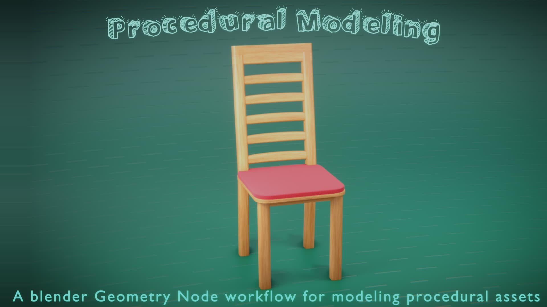
Procedural Modeling is a modeling technique that enables us to create dynamic 3D models based on a set of rules, instructions, or algorithms such that changing the parameters of these rules produces different variations of the model. This article will focus on how we can make procedural models in blender using geometry nodes.

APPROACH
The goal is to produce the largest number of unique 3D models with the least amount of effort by letting the computer handle some part of the modeling task. To do that, first, have to define a consistent procedural workflow that can be applied to almost any asset.
Abstraction
-
Most objects regardless of complexity are actually made up of simple modular components:
-
These components can be modified individually which will result in an entirely different model of the same asset class or category:
-
Taking this idea further, we can think of modular components as just instance points. Hence, the complete 3D model can be abstracted to a combination of points in space.
We can therefore build any 3D model we want by first creating and transforming these points, after which the different modular parts can then be instanced on the appropriate points:
Variations
Static Component Replacement
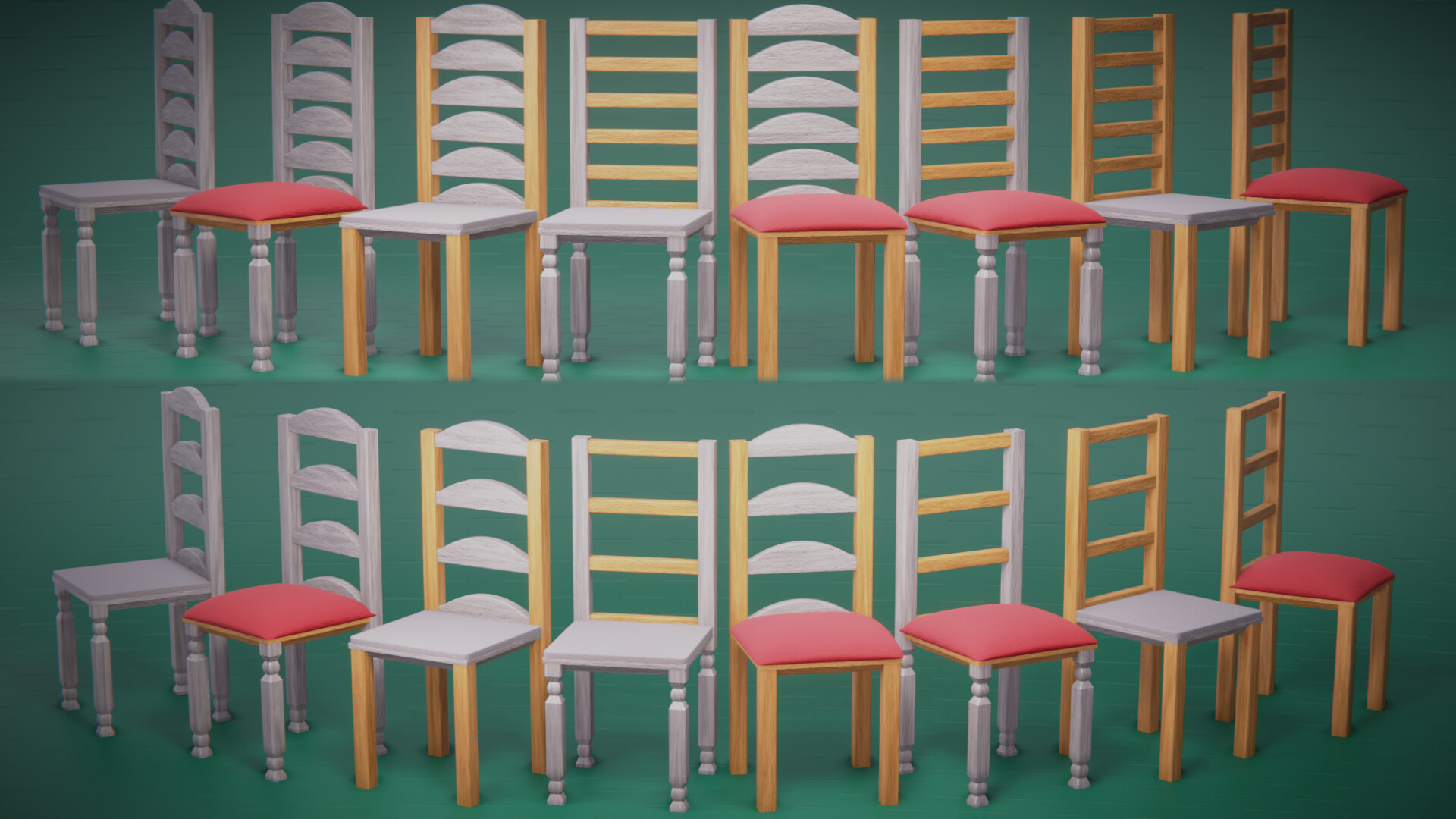
The obvious approach to creating new variations of the 3D model is to replace the existing modular components with new ones on the instance points. With this setup, we can produce a lot of models very efficiently. The total number of models that we can generate is a product of the number of variations of the modular components.
For example, if we have two different chair models where their differences are in 3 parts; the leg, the seat and the shape of the cross rails. If we separated these components into modules and made a procedural chair out of them, we will have eight (2x2x2) possible different chair models.
If we added one more component variation to it, say, changing the number of cross rails from 6 to 4, then the total number of possible chair models will double to 16!
Dynamic Component Blending (shape keys)
Instead of replacing the components with new ones, a more interesting approach would be to create shape keys (blend shapes) of the components. Hence, generating new variations of the 3D models is just a matter of blending between different shape keys. The number of 3D models that can be generated this way is technically infinite since shape key blending is continuous.
The downside to this approach is that shape keys have a fixed vertex count limitation. Making extreme component variation where the shape is drastically different from the previous component or more geometry is needed for extra details will be almost impossible because of this limitation.
Therefore, the best approach is to combine both the static and dynamic variation depending on the context.
Component Transformation
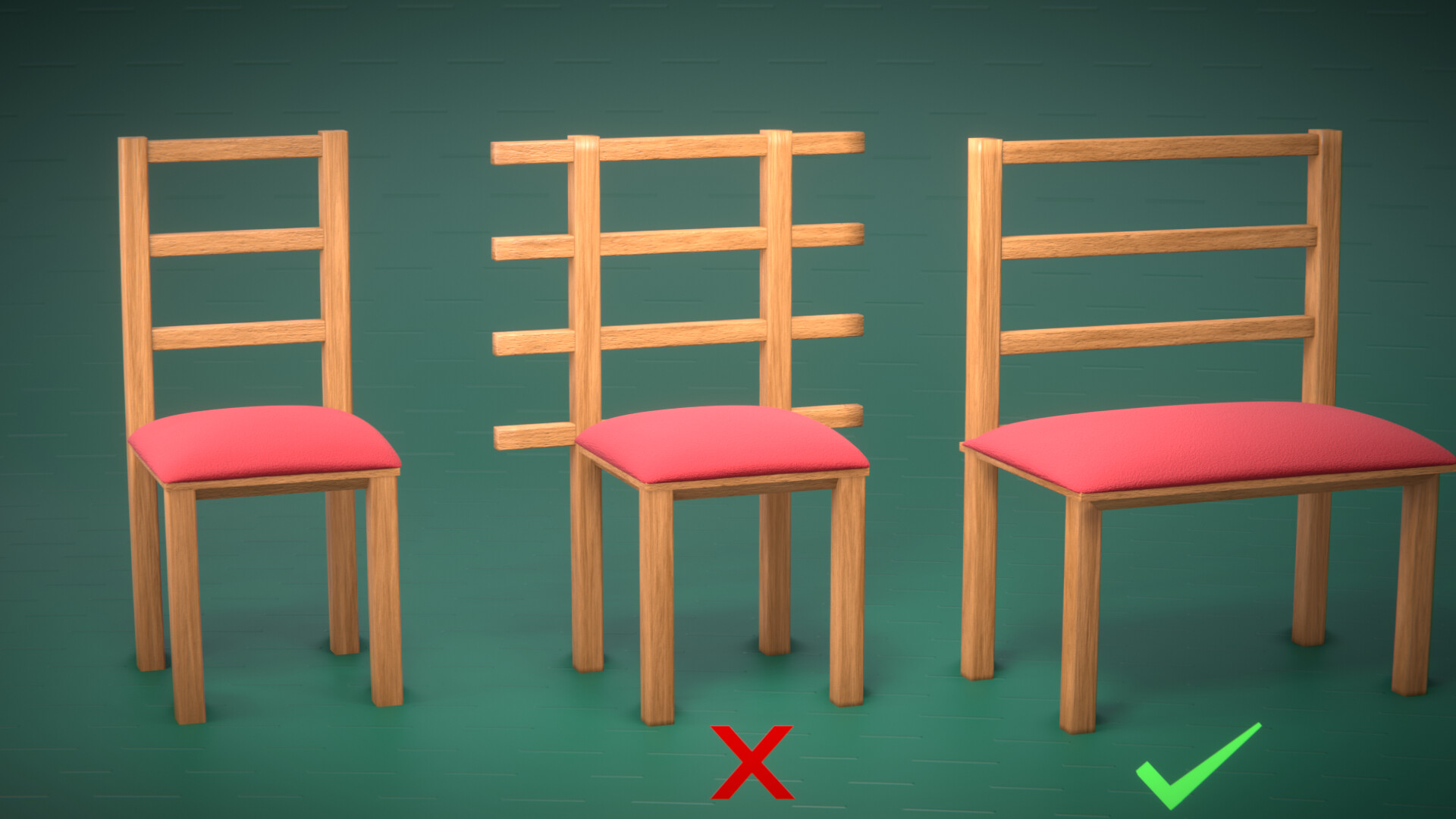
Sometimes, we get new model variation by simply scaling, rotating or translating a component. This can however lead to an obvious problem where other components are not adjusting to the transformation of a component leading to undesirable intersections
This actually applies to all the various approaches. Hence, we need a robust solution that can handle smart components adjustment to change. This is what will be discussed next.
Modular Hierarchy
As discussed above, we need to find a way to compensate for changes such that when the shape of one component changes, other components adjust appropriately keeping their relationship consistent and retaining the structural behaviour of the asset class. For example, when the seat of the chair model is scaled on the X-axis, the legs of the chair need to move on the X-axis as well to retain their relative position to the seat, whereas, the cross rails only need to scale on the X-axis by the same factor.
An approach to automatically handle the relationship between modular components is to create the procedural model in a hierarchical fashion similar to how rigs (Armatures) work.
-
Just like in amateurs, the modular components will be set up in a parent-child fashion starting from the root component.
-
The child inherits the transformation of its parent while still having its own local transforms.
-
The parent can also have other children but each child has just one parent.
-
The only difference between this system and the armature system is that the children components only have their “position” affected by the transform of their parent. Their scale and rotation are solely controlled by their local transform. For example, if the parent rotates or scales up, the child adjusts its position appropriately such that its relative position in the parent space always remains the same.
To implement such a system, the position of the child component needs to be controlled by the bounds (bounding box) of its parent. Interpolating between the bound minimum and bound maximum should position the child on all possible locations in its parent space. Then the child needs to also have a local position parameter just as expected from the above description. The actual implementation will be covered later in the Implementation section.
Conclusion
There are still other concepts we need to consider to make the procedural modelling pipeline robust enough to handle modeling almost any kind of object procedurally. These concepts include handling component array, components mirroring, component behavioural dependencies (the variations of a component behaving differently depending on the behaviour or variation of the higher parent components in the hierarchy), etc.
However, all these can be implemented once the foundational design works properly. Hence, all these will be considered later.
IMPLEMENTATION
The implementation is still a work in progress so updates on that soon!