The amount of detail and documenting is simply astounding… love this project. I haven’t had time to work much on projects lately, I’m glad you aren’t constrained in that regard as it’s obvious you have spent a LOT of times on this… keep it up.
NRK, thank you very much!
Today: the tail wheel
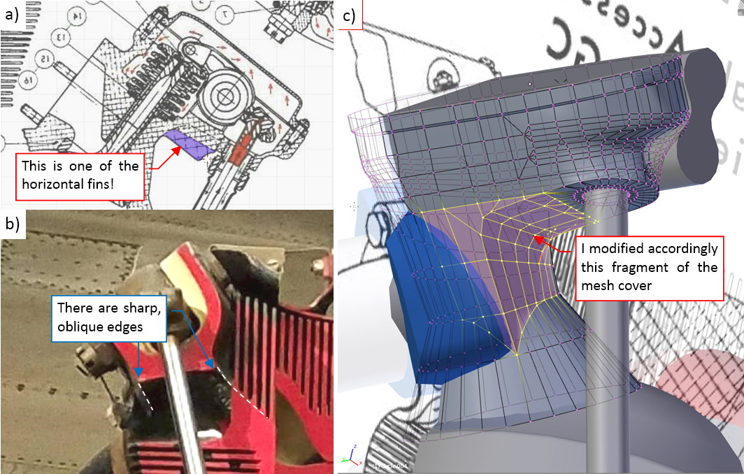
The Dauntless had fixed tail wheel of a typical design among the carrier-based aircraft. The tail wheel assembly consisted a fork connected to two solid-made beams, which movement was countered by a shock strut. The beams and the shock strut were attached to the last bulkhead of the fuselage:
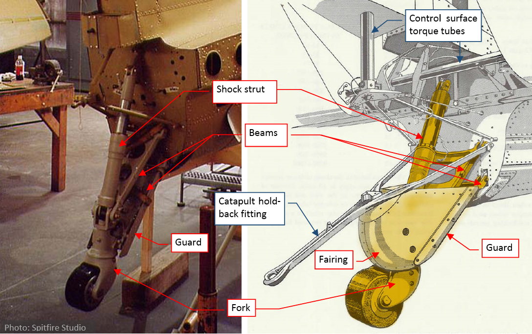
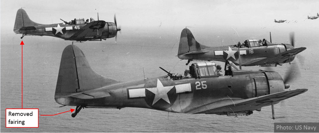
The bottom part of this assembly was covered by a guard and a fairing. Both of these elements were attached to the lower beam. The archival photos reveal that the bulky fairing was often removed:
There were two tail wheel versions: the smaller, solid-rubber wheel for the carrier-based aircraft (as in figures above), and the larger, pneumatic wheel for the ground-based aircraft. As you can see on the example of a SBD-1 (below), they could be replaced in a workshop:

Figure above shows two SBD-1s, which were exclusively used by USMC squadrons in the continental United States. All of these 57 aircraft were built in 1940. As you can see in the photo above, they were originally delivered with small, solid tires. However, in the photo below, taken a year later, one of these SBD-1s has the large, pneumatic tail wheel. It seems that Douglas delivered these large wheels to the Navy / USMC as an optional kit, which could be mounted when needed.
The smooth tip of the tail was mounted to the last bulkhead as a light, easily detachable tail cone. It covered the tail wheel shock strut, as well as the rudder and elevator control mechanism. There was a large opening in the bottom of the tail cone. For certain sunlight directions (for example, in a dive) you could “look inside” the fuselage:
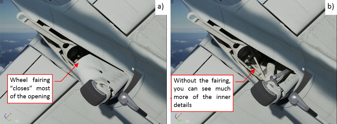
As you can see in the figure on the left, the tail wheel fairing effectively closed most of this view (figure “a”, above), so that you could see just the catapult holdback fitting, two ribs and their stringers. However, when you remove this fairing, you can see many details inside (figure “b”, above). Of course, they are not visible on most of the photos. These details are hidden in the pictures taken on the ground. In most of the in-flight photos this opening seems to be too small to reveal the interior details. However, thinking about the future scenes of diving bombers, I decided to recreate at least the key internal elements of this tail cone.
While the tail wheel in the SBD does not retract, it follows the shock strut compression. Thus recreation of this assembly requires some initial adjustments of these moving parts. (For example: I had to make sure that the wheel leg will fit into the tail cone). I am shortly describing this process below:
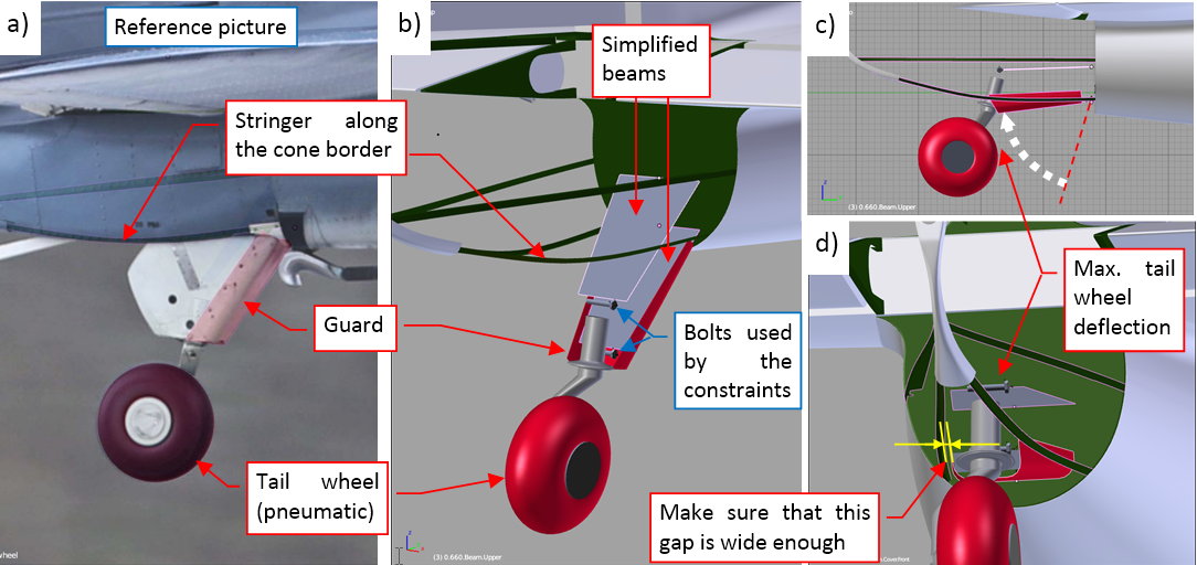
I started with the tire, its fork and the guard, which are present on my reference photo (figure “a”, above). I also added the stringers along the border of the opening in the tail cone. Then I placed the simplified shapes of the tail wheel beams. At the beginning I did not know their proper width, thus their initial mesh was a simple, four-vertex trapeze, ready for eventual adjustments. In figure “b”, above, you can see also a bolt at the end of each beam. They were important parts of this “virtual mechanism”. No armature was needed in this case. I decided that the lower beam will be animated by the handle movement. Thus I forced the upper beam to follow its rotation using a Copy Rotation constraint. Each of these two bolts is attached (by parent relation) to the corresponding beam. The tail wheel fork is attached (by parent relation) to the lower bolt. Simultaneously this bolt rotates, tracking the center of the upper bolt (using a Locked Track constraint). Thus, when I rotate the lower beam, it rotates the whole assembly (as in figure “c”, above). Then I adjusted the width of the guard and the beams so that in the fully deflected position it fits the opening in the tail cone (figure “d”, above).
Once the overall size of the beams was determined, I recreated their shapes, as well as the catapult hold back fitting, shock strut, and the tail wheel fairing:
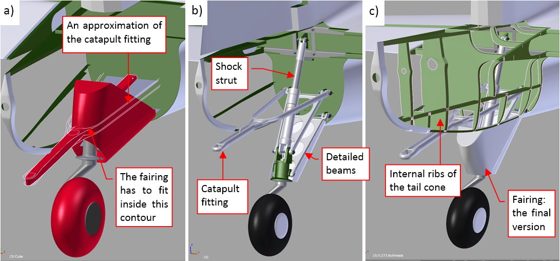
The catapult fitting was attached to the ribs of the tail cone. Its side arms were fitted between the tail wheel fairing and the stringers running around the border in the tail cone opening. As you can see in figure “a”, above, I started with the conceptual lines of this part. Then I used them to form the final “Y” – shaped fitting (figure “b”, above). Using similar methods I recreated the beam details. (I could do safely, because they were already fitted to the tail cone, and I do not expect any further changes in their shape). Finally I also added the internal ribs of the cone (figure “c”, above).
In the next step I recreated the rudder/elevator torque tubes and their fittings:
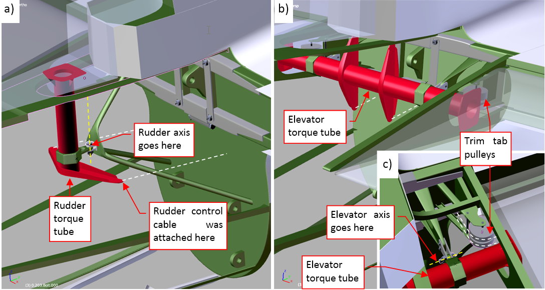
Figure “a”, above, shows the rudder torque tube. It was mounted on a tripod. Note, that the rudder rotation axis lies in the front of this tube. (It rotated around the bolt that joined the torque tube with the tripod). For this level of detail I did not recreate the control cables. (Perhaps I will do it in the future). I also formed the elevator torque tube (figure “b”, above). Its rotation axis also lies in the front of the tube. According the maintenance manual, there were also two pulleys for the elevator trim tab cables (figure “c”, above). Unfortunately, I do not have any precise photo of this detail. I recreated their brackets using two rough sketches from the maintenance manual, but about 50% of their size and shape is just my guess. If any of you have a photo of the details from figure “c”) (for example – from a restored SBD), let me know. I would appreciate any of such pictures.
Figure below shows all of the tail cone internal details that I have recreated so far:
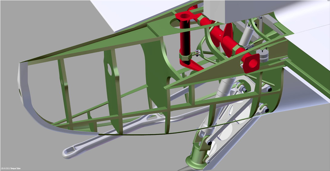
For the assumed level of details I simplified some small elements, like the trim tab pulleys. I also did not recreated other minor, less visible elements like control cables, electric cables, some additional fittings and bolts. I will recreate them later, when I decide to make cutaway pictures of this model.
To recreate the alternate, “solid” version of the tail wheel, I switched to another reference photo:
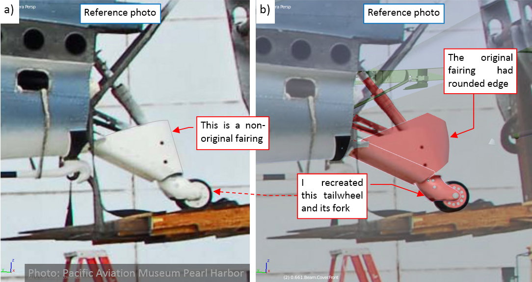
The SBD on this reference photo was restored for Pacific Aviation Museum Pearl Harbor. Although the restoration teams do their best to recreate their “birds”, sometimes you can find a non-original part on their aircraft. In this case it was the tail wheel fairing: it is smaller and simpler (figure “a”, above) than the original part (figure “b”, above). However, the rest of the tail wheel assembly seems to be original, thus I used this photo as the reference for the “carrier-deck” version of the tail wheel and its fork.
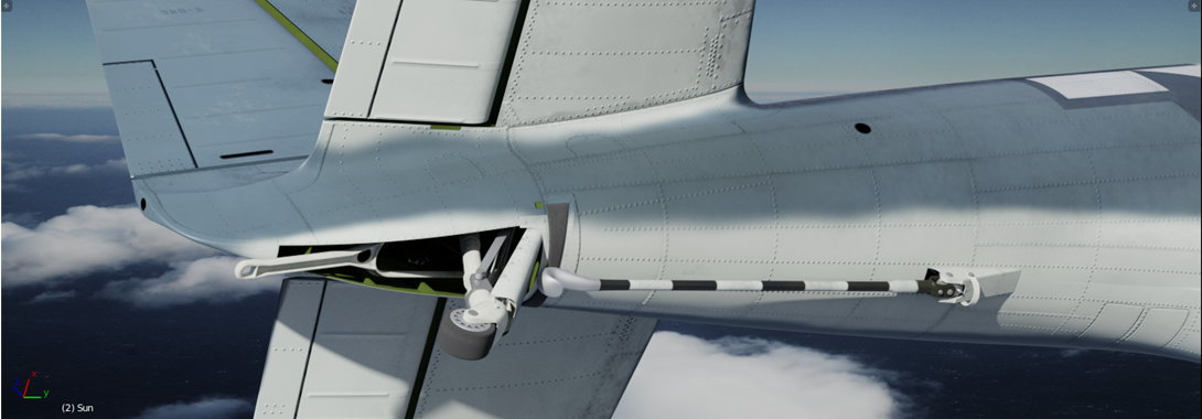
Finally I also added the tail hook (it was removed only from the A-24s, delivered to the Army). As you can see, it was accompanied by some minor details:
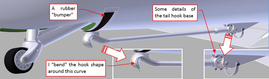
Figure below shows the final result: the complete tail wheel and hook assemblies:
As you can see, I initially painted the internal surfaces using the standard Interior Green color, but then I was starting to have doubts. In the restored aircraft these surfaces are usually painted in the gray camouflage color (the same as used for the aircraft underside). Unfortunately, I did not have any historical photo of this area to determine how it was painted in the original SBDs. Most probably I will update the color of this detail according the restored aircraft.
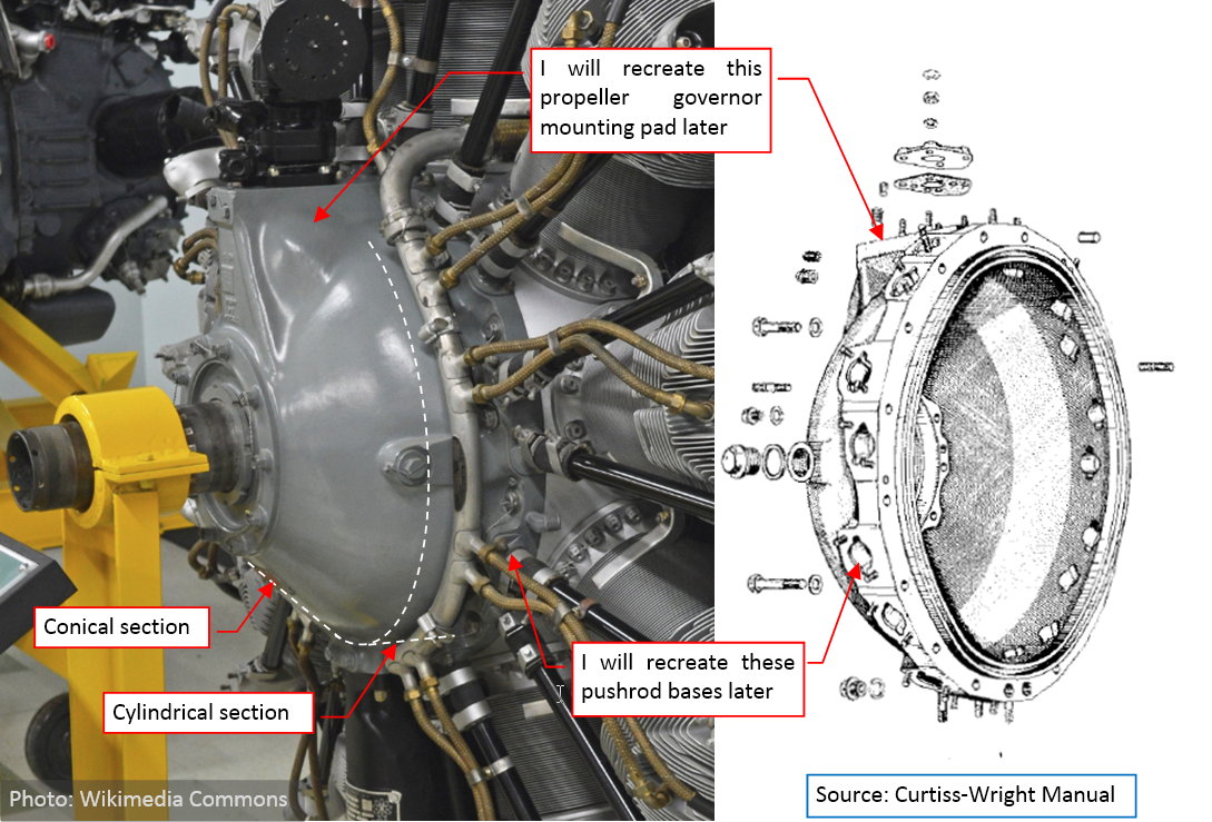
The next part I am going to recreate is the R-1820 engine (a simplified version, for the external pictures). However, for reasons beyond my control I have to take a break from this project. I will write next post in the spring (2018). So, for time being my SBD will look like this:
In this source *.blend file you can evaluate the model.
Hey @Witold, long time no see…it’s been a while since I was here on BA, great job and you never stop in amazing me with your level of detail and work…dude you are a Master of Masters!
Great progress with the Dauntless…A1 job!
@tommy1441: thank you!
After the long winter, finally we have fresh spring, and I am back at my old desk!
I started working on the most complex part: the Wright R-1820:
The engine is the heart of every powered aircraft. In the case of the SBD it was the Wright R-1820 “Cyclone 9” (the “G“ model). In fact, this engine was one of the “workhorses” of the 1930s: designed in 1931, it was used in many aircraft, especially in the legendary DC-3. “Cyclone” was a reliable, fuel-saving unit for the Navy basic scout type. (Remember that the “Dauntless” was not only the bomber: it was also a scout airplane[SUP][1][/SUP]). In general, the R-1820 is a classic nine-cylinder, single-row radial engine:
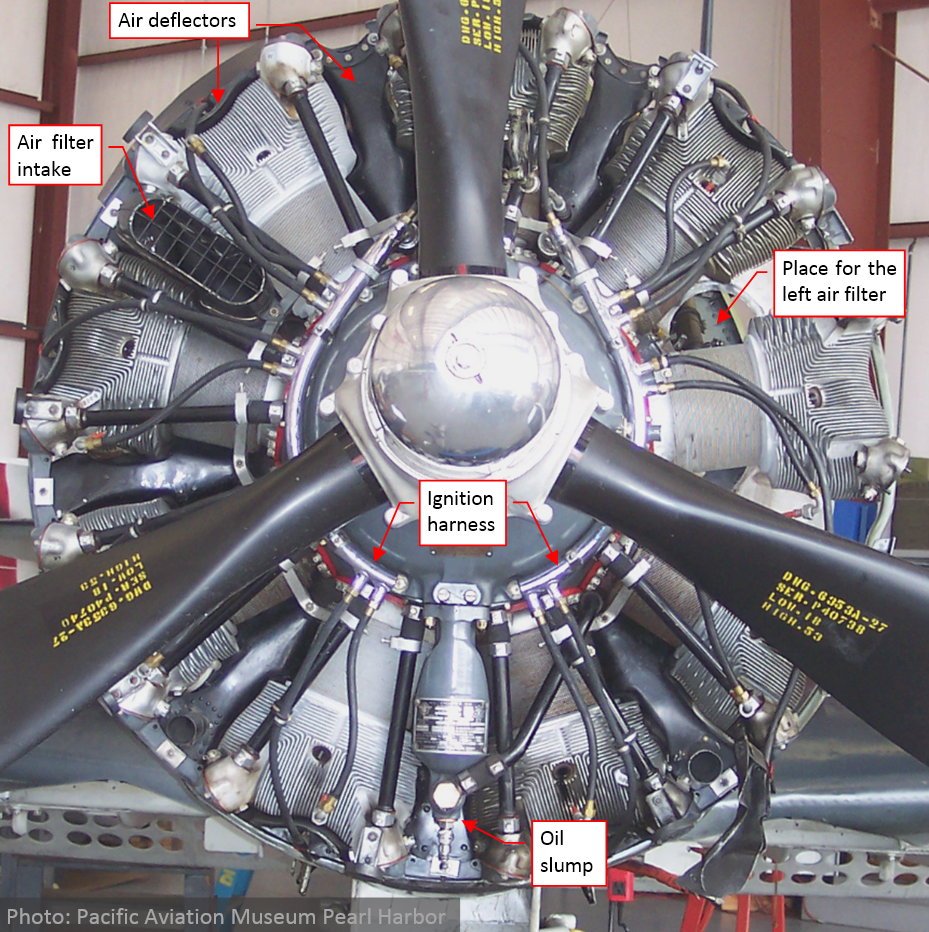
The R-1820 G had been produced for over two decades, not only by the Curtiss-Wright, but also (under license) by Lycoming, Pratt & Whitney Canada, and Studebaker Corporation. Thus various less important details of this engine “evolved” during this period. In this post I would like to highlight some of these differences. I will focus on the forward part of this engine, because at this moment I am going to create a simpler model of the “Cyclone”, intended for the general, “outdoor” scenes. Inside the closed NACA cowling, you can see only its forward part. (Thanks to the air deflectors, placed between the cylinders - see picture above). In such an arrangement, the visible elements are: the front section of the crankcase, cylinders, ignition harness, and the variable-pitch propeller governor. While the front section of the R-1820 crankcase remained practically unchanged in all versions, and the governor depends on the propeller model, I could focus on the cylinders and their ignition harness.
Identification of the version differences is the basic step, because otherwise you can build a model of non-existing object that incorporates features from different engine variants.
BTW: do you know, that the R-1820 design had remarkably long life? The United States factories produced the last batch of these engines in 1964. The metric version of the earlier “F” model had been produced in Soviet Union under Wright’s license since 1934. A few years later Soviet engineers developed its enhanced version: Ash-62 (resembling the “G” model of the “Cyclone”). Ash-62 was widely used in 20th century aircraft of the former eastern block (especially – in the popular Antonov An-2), and had been produced under Soviet license in many countries. Actually the last factory that still produces these engines is PZL WSK-Kalisz in Poland. They provide new units for the last flying DC-3s, An-2s, and M-18s, as well as the overhauling services. Who knows, if this “eastern branch” of the R-1820 will last long enough to celebrate the 100th anniversary of the famous Wright design?
While looking for the reference materials, I have also found an interesting article about the development of air-cooled aviation engines (more precisely, their most important parts: cylinders). I think that it provides a valuable “technical context” for the visual differences that I am describing below.
Searching for the reference photos, I have identified two basic variations of the “Cyclone” cylinder shape:
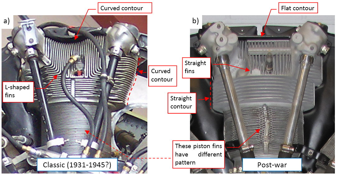
Figure “a” above shows the classic version, produced to the end of the WW2, while the cylinder from Figure “b” comes from the post-war production. I will refer this earlier one as the “classic” version. This is the engine used in all SBDs. You can quickly identify this version by the characteristic “L”-shaped fins on its cylinder head (Figure “a”). The “classic” head has also curved contours, while the head of the post-war version has different style, and its contour is based on the straight lines. Both heads are aluminum die-casts. The critical element in this design was the overall area of their fins. Greater cooling area of the cylinder head allows you to obtain more power from the same piston volume. Thus the fins of the “classic” head are small wonders of the 1930s metallurgy: they are evenly spaced at 0.2” (5mm) along the head, and the widths of their tips do not exceed 0.05” (1.2mm). The fin at its base is about 0.1” (2.5mm) wide. Die-casting of such an object is extremely difficult. It requires not only the “written down” engineering knowledge, but also individual artisanship of the key workers. Note that the spaces between the fins of the post-war head are two times wider than in the “classic” version. However, between each pair of these “full-size” fins there is a smaller, much shorter “inner” fin. It is much easier to die-cast such a head. I suppose that the post-war heads are cast from an aluminum alloy that has better heat transfer characteristics. It would allow their cylinders to maintain similar power output using somewhat smaller cooling area.
The cylinders of the last R-1820 versions had yet another, conical shape:
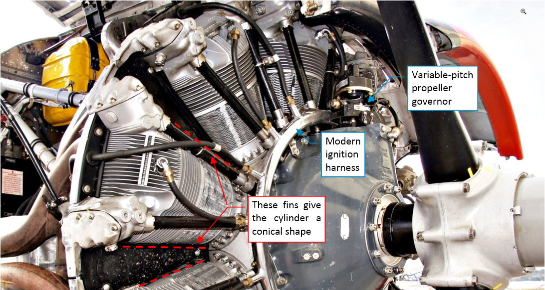
In this photo you can also see here the propeller governor (in the first photo in this post it is hidden behind the propeller blade), and another version of the ignition harness.
The “classic” and the “post-war” cylinder heads have different orientations of their intake openings, which results in different shape of the intake pipes:

The classic version has a simpler, L-shaped intake pipe, which fits to the oblique opening of the intake valve (Figure “a”, above). In the post-war version planes of both valve openings (exhaust and intake) are parallel (Figure “b”, above), thus the intake pipe has a more complex shape (resembling “S”).
In fact, Figure “b” above shows the smaller, 7-cylinder version of the Wright Cyclone (R-1300). However, it used the same cylinder and intake ducts as the late R-1820. (I just could not find a shot similar to the Figure “a” of the late R-1820 version, so I used the picture of its “smaller brother” instead).
There are also minor differences in the rocker covers:
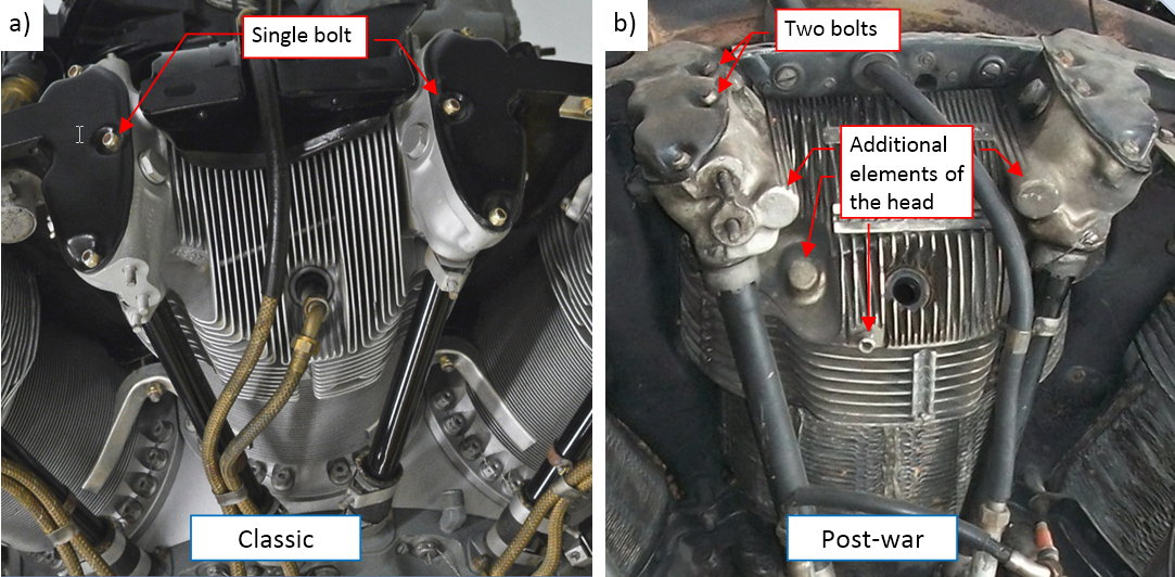
The classic version has simpler, four-bolt rocker cover (Figure “a”, above), while the post-war covers uses two bolts more. The head of the post-war engine has some additional features (Figure “b”, above), which do not exist in the classic head.
Finally, the ignition harness:
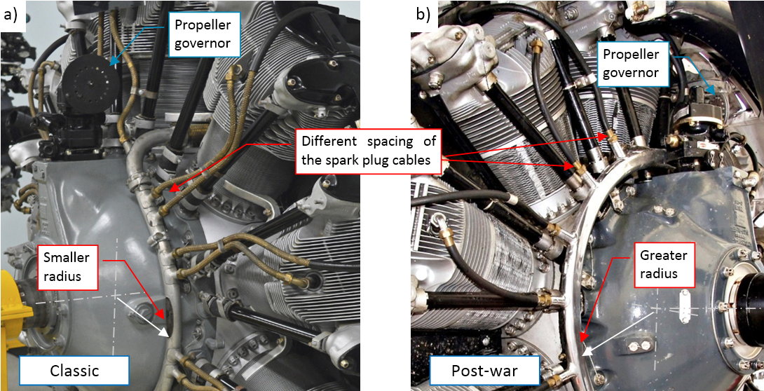
Classic ignition harness has a “collar” shape, smaller radius, and individual spark plug cables organized in pairs (Figure “a”). Post-war harness has a ring shape, somewhat greater radius, and evenly spaced spark plug cables (Figure “b”). Although each of these photos is taken from different side, it seems that both versions use the same propeller governor.
Having all these issues identified, I could select appropriate reference drawings. They came from “Cyclone 9GC Overhaul Manual”, published in 1943. I expect that even the simplified model of such an engine can have many hundred thousand faces, thus I decided to build it in a separate Blender file. I use the same “scale” as in the SBD model: 1 unit = 1 inch. When it is ready, I will import it into the SBD model.
In this new Blender file I decided to give chance to the alternate method of setting up the blueprints: using Empty objects with the attached image:

First I placed on the perpendicular planes the four views of the original installation drawings (Figure “a”, above). Note that they contain a lot of the explicit dimension values – such information is an invaluable help in recreating this engine.
I quickly realized that the Empty objects with the reference images allow you to use simultaneously several alternate sets of the blueprints. Just place each of them on a separate layer. It will be a great tool in the Blender 2.8, which has to have unlimited number of layers. While working in the actual Blender 2.7, I placed these planes on layers 7…10, practically reserving them for the reference pictures. The second blueprint set contains the images from the original “Limits and Lubrication Chart” (Figure “b”, above). These two views (side and rear view) are much more detailed than the installation drawings (presented in Figure “a”, above). Of course, these images do not match each other in a perfect way: there always are some differences. However, I did not fix them, as in the case of the SBD planes, because all the key dimensions of this engine are specified in the installation drawings. I will just use these explicit values.
Following the standard of my posts, I am enclosing the current state of the source *.blend file. While there is no model, yet, you look inside to check the arrangement of the reference pictures. Next week I will report the first stages of building this model: forming the central crankcase and the basic cylinder shape. (Cylinders of this engine are identical with each other. Once you prepare one of them, you can quickly “populate” the crankcase with its eight clones. However, as you will see in the next posts, the die-cast, air-cooled cylinder head is one of the most complex objects to model…).
[1]The SBD Dauntless was a new implementation of the US Navy carrier doctrine, worked out in the preceding decade: in the clash of the carriers always wins those, who first finds carriers of their opponent. In fact, the best option was to find, report, and immediately make the first attack – that’s why all SBDs carried a 500-pound bomb on their scout missions
1 Like
In this post I will recreate the main and the front sections of the R-1820 crankcase, and the cylinder basic shape. Let’s start this model by forming the main crankcase:
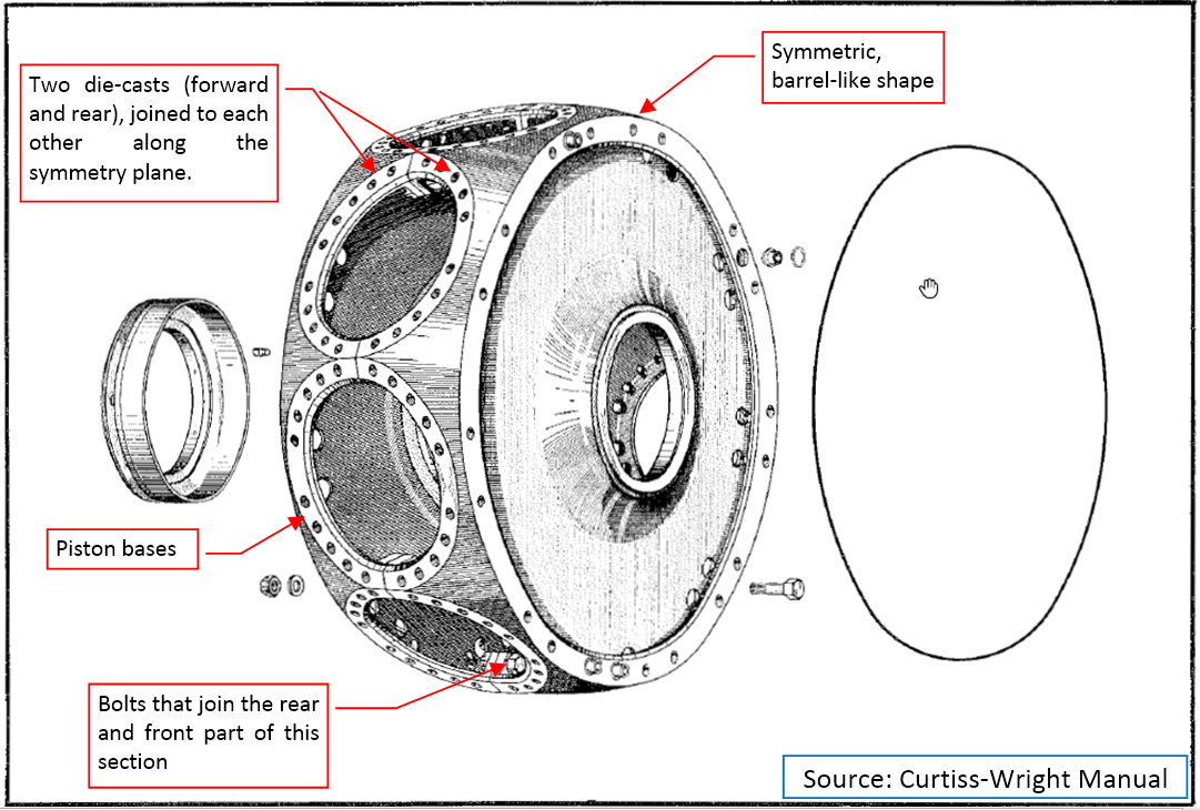
This section is always obscured by the cylinders, so you cannot see it clearly on any photo. That’s why I used here the original drawing from the manual. Generally, this barrel-like shape contains nine cylinder bases. It is formed by two steel castings, bolted to each other. (These bolts are hidden inside the crankcase, between the cylinder openings).
It is always a good idea to start with a simplified model. It allows us to check all constrains of the geometry that are not obvious at the first glance from the reference drawings. In this case started by forming a symmetric half of the crankcase:
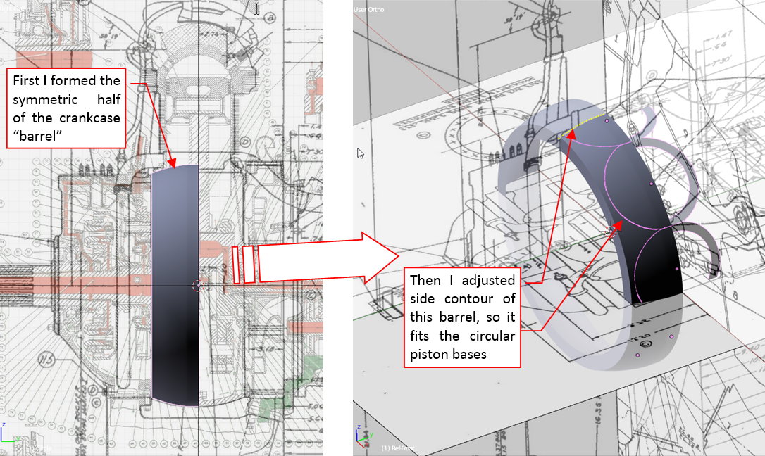
This is a simple barrel, smoothed with a Subdivision Surface modifier. Then I placed the flat piston bases along the circumference of this crankcase. I quickly realized that the side contour of this barrel depends entirely on the size and shape of these piston bases. After a few quick adjustments of the control edge loops, the barrel surface “touched” the outer edges of the piston bases along their whole length (as in figure above).
Note that these piston bases are so tightly packed around the crankcase, that they nearly join each other along a short, straight edge:
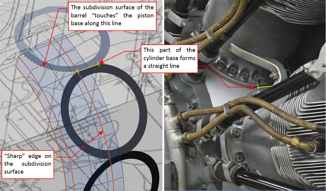
This means, that the crankcase barrel contains a cylindrical strip in the middle, which matches this straight edges on the piston bases. In fact, the sharp corners of these edges forced similar sharp edge on the barrel side contour.
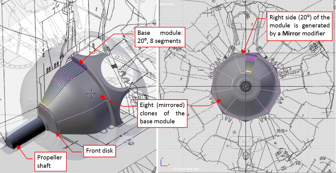
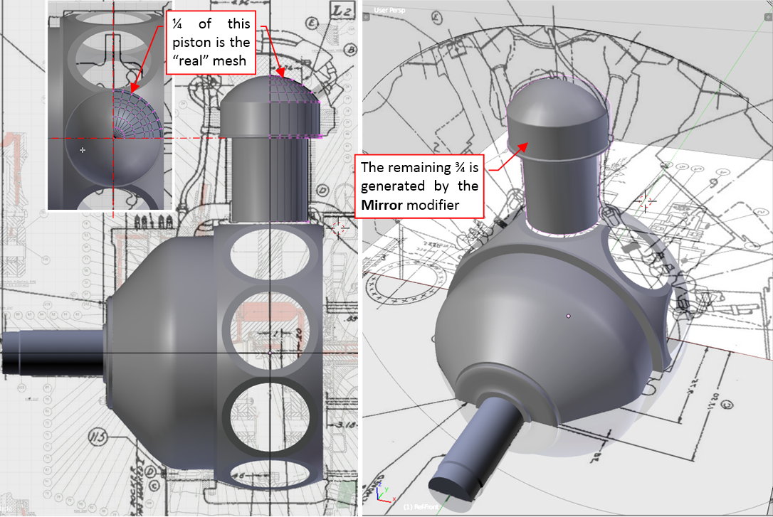
When the general shape of the crankcase barrel looked right, it was time to create the final mesh. I decided that I will not use the dynamic effects of the subdivision surfaces for such a complex objects as the engine parts. (Because I want to keep the polygon count of this engine model below 1 million). Thus I “fixed” this subdivision effect, converting it into the normal faces (by “applying” the modifier). Then I took take the advantage of the “repeatability” of this shape. I deleted all the faces of the original “barrel”, leaving just the 20⁰ “slice” (as in figure “a”, below):
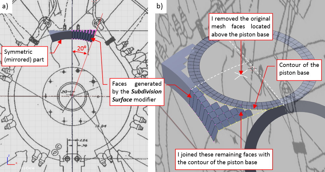
The opposite 20⁰ of this “slice” is generated by the Mirror modifier. Then I made further modification to this mesh, removing all the faces from above the piston base (figure “b”, above). I also copied and inserted into this mesh a quarter of the piston base contour. Then I started to join this contour and the mesh around it with new faces. You can see the result in figure “a”, below):
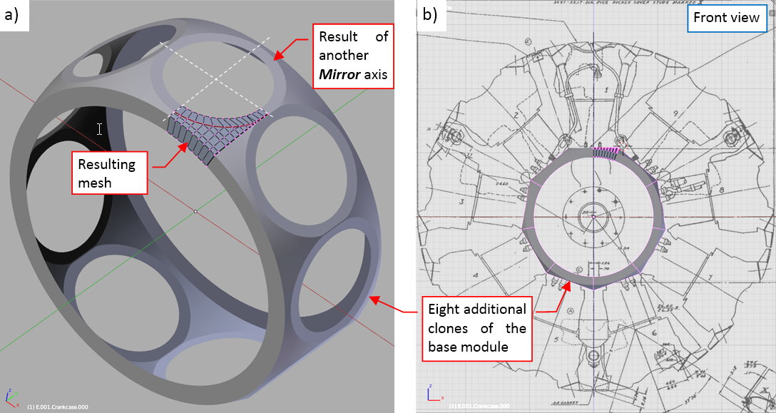
As you can see, I also recreated the rear part of this crankcase section, just adding another symmetry axis to its Mirror modifier. The whole body of this crankcase can be built from 9 clones of such an object (as you can see in figure “b”, above).
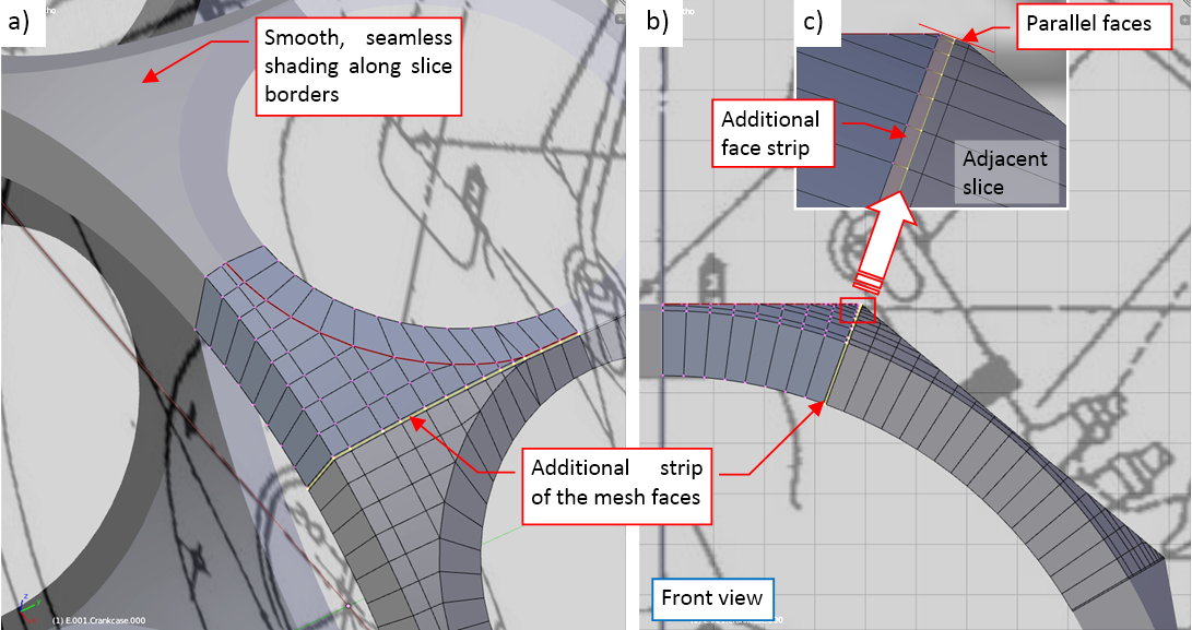
The shading of the crankcase faces is set as Smooth, except the faces around the piston base (which are marked as Flat).
I would like to mention a little “trick”, which can be useful in many other cases. To obtain a seamless join between the crankcase “slices” (as in figure “a”, below), I added an additional, thin “strip” of the faces around the slice edge. These faces are parallel to the faces of similar strip in the adjacent slice (as in figures “b” and “c”, below):
Once the middle section of the crankcase is ready, I started working on its front section. Generally speaking, this part looks like a combination of a cone and a cylinder, with many “protrusions” of additional details:
Actually, I recreated the basic shape of this section. (I will recreate the remaining details later). I did it using the same workflow as in the case of the previous section. First, I made a simple, “conceptual” model of this part. It was smoothed using a Subdivision Surface modifier. When the shape seemed to be OK, I converted the result of this modifier into normal mesh faces. Then I removed all the unnecessary edge loops and created the basic 20⁰ “slice” of this section:
To obtain the smooth shading between slices, I also created the additional thin strips of parallel faces along their adjacent edges. The basic slice of this section was easier to form than the one from the middle section, because it did not contain any opening.
Just to make the front of the engine more complete, I created the front disk (in a classic way, no “slicing” here) and the propeller shaft.
Finally I started working on the cylinder. Because all cylinders of this engine are uniform, I will complete a single (the topmost) one. The complete cylinder will be an assembly of many objects. Then, when it is finished, I will clone it around the crankcase.
As the first object in this assembly I created the simple, basic cylinder (i.e. the cylinder and its head without the fins and rocker covers):
It will be the parent object of all further elements of the cylinder assembly. As in the case of the crankcase, it does not use any Subdivision Surface modifier, just the “fixed” mesh faces with the Shade Smooth option (and Mirror and Bevel modifiers).
You can check details of this model in the source *.blend file. In the next post I will model the rocker covers and the covers of the intake/exhaust valves. (In the R-1820 they are just fragments of a single-piece cylinder head).
1 Like
dude, you sure do know your stuff! excellent work.
Stunning work, as always.
heraSK, thorst, boblybill - thank you!
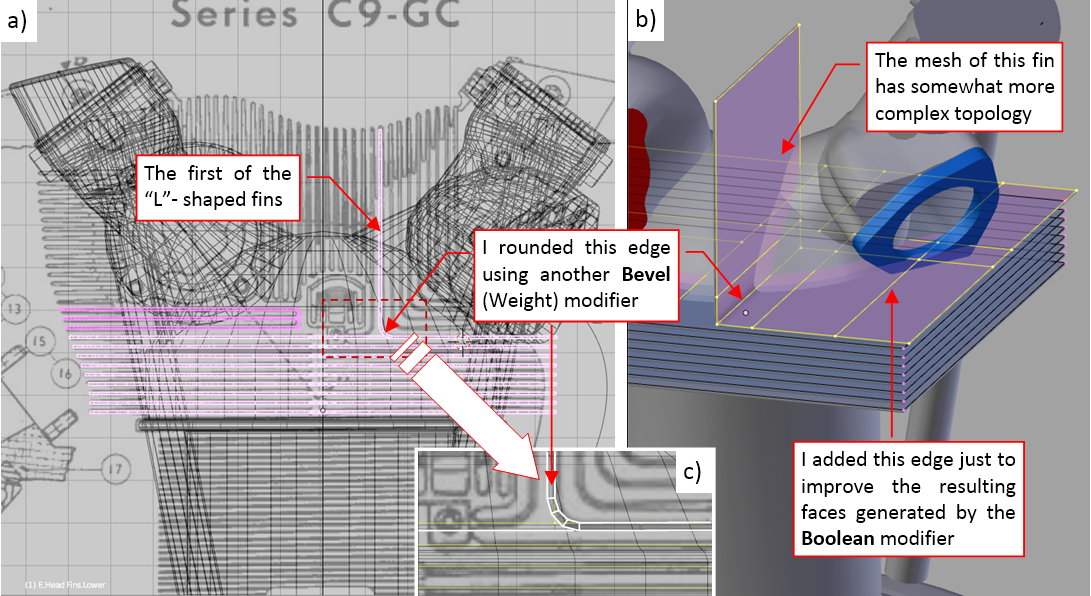
In this post I am wrestling with the partially hidden shape of the cylinder head:
One of the most prominent features of the R-1820 engine cylinders are their rockers. More precisely – their covers, cast as the part of the cylinder head:
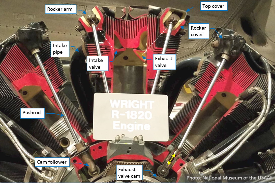
The R-1820 was a classic four-stroke engine. Its cylinders had two valves: single intake valve, connected to the supercharger via a wide pipe, and single exhaust valve. Movements of these valves were controlled by cams, via pushrods and rocker arms mounted in the cylinder heads. The covers housing these valves and rocker mechanisms were placed on the right and left side of the cylinder head.
To simplify my model, I decided to separate the cylinder fins from its “solid” body (i.e. to create them as separate objects). However, because in the reality the cylinder head was cast as the single piece, it is very difficult to precisely determine its shape hidden between these fins:
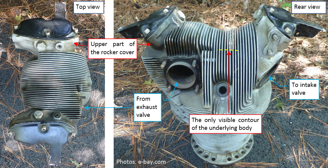
While you can see the upper parts of the rocker covers on the reference photos, you can only guess their contours below the “fin surface”.
There is a blueprint that provides some additional clues:

However, I have some doubts about details of the contour that you can see on the rear view above. (I marked it with thick dashed lines in the picture). Look at the lowest part of this top contour: it should correspond to the upper (outer) surface of the combustion chamber. According other drawings, the shape of this chamber resembled a regular dome. If so, why the fragment of its contour visible in this drawing seems to be (a little) oblique? In the cutaway depicted in the first photo in this post I cannot see such an oblique shape. And why the side contours of this heads (the vertical dashed lines below the valve openings) are not symmetric? Thinking about it, I concluded that this drawing was not focused on the precise representation of the cylinder geometry: its main goal was to show the lubrication areas. Thus all these details, which we can see here, were drawn thanks to a “good will” of its draughtsman. They were hand-made, ink-traced drawings, and we can be just thankful to this technician for such a detailed piece of work. Still, I assumed that these lines can differ a little from the real contours – just because of the plain human error.
I formed the basic shape of the rocker cover using two clones of the same mesh: I placed one instance on the auxiliary drawing, while the second instance is located in its proper position on the cylinder (Figure “a”, below):
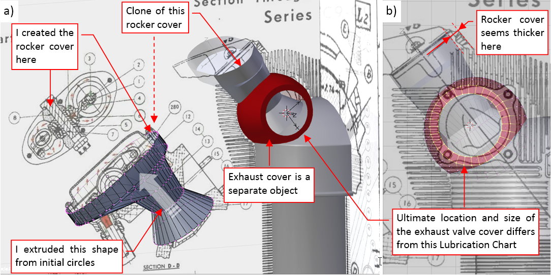
Modeling this cover as a separate object allowed me to switch between its local (along the valve axis) and global coordinate systems. I could also modify this mesh switching between its clones. I used the instance, located on the cylinder, to fit its base into the combustion chamber dome. The other instance of this cover, placed over the auxiliary drawing, allowed me to follow the shape of this element. (In fact, I could also put another instance of this mesh over the top view of the rocker cover. However, I did not do it - just because I used this view only during the initial phases of the modeling, and it was relatively easy to rotate the modeled object and move it over the side view).
This is the initial, “conceptual” model of the cylinder head, so I split it into the key “solids” and formed the semi-spherical cover of the exhaust valve as another object (the red one in figure above). Such an arrangement allows for easy manipulating of these parts. During this phase I have to determine their most probable sizes and locations. For example – following the precise location of the exhaust opening, I discovered that for the size as in the “Lubrication Chart”, it has to be placed in a slightly different position (as in Figure “b”, above). Otherwise, the right-bottom corner of the rim around exhaust opening would “sink” into the combustion chamber dome. (Of course, I also checked multiple times the most probable radius of this dome!).
When the whole thing seemed to match the photos, I made the rocker cover asymmetric (by “applying” its Mirror modifier and modifying the resulting faces). Then I modeled the oblique pushrod base (Figure “a”, below):

To avoid some potential errors in the future, I started with placing the pushrod (another object) in the proper position, then formed the base around it. Figure “b”, above) shows the resulting mesh. Note the sharp edges in its upper part. In the next step I rounded them, using a multi-segment Bevel modifier (Figure “a”, below):
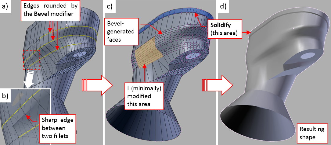
To have more control over these fillets, I used the weight-based version of the Bevel. Figure “a”, above, shows the mesh edges that have a non-zero bevel weight marked in yellow. However, even in such a case, I could not avoid an artificial sharp edge between two fillets that were too close to each other (Figure “b”, above). Well, in this situation I had to “apply” this modifier, and manually introduce small fixes to the resulting faces (Figure “c”, above). I also dynamically created a “rim” around the upper edge of this cover. It is generated by the Solidify modifier, assigned to the thin face strip around this edge. Figure “d”, above) shows the final result of these modifications.
While working on these parts, I simultaneously “scanned” the Internet, searching for more reference photos. Sometimes they just expose details, which were obscured in the reference materials that I already have. In this case – it was a protrusion on the rocker cover around the first and the last bolt (Figure “a”, below):

I just had missed this tiny detail while forming the upper part of the rocker cover! Now I had a headache, how to fix it in a quick way. Ultimately I prepared two reference “cylinders” (I marked them in red, as you can see in Figure “b”, above. Fortunately, there were many faces around the area that I had to modify. I placed these faces on the corresponding reference cylinders using the Blender Sculpt tool. (It allows me to push/pull multiple faces at once in a gradual manner).
You can see the final result of this modification in Figure “a”, below:
Frankly speaking, I can see now that this protrusion had somewhat smaller radius. Ultimately I decided that it is “good enough” for the assumed level of details.
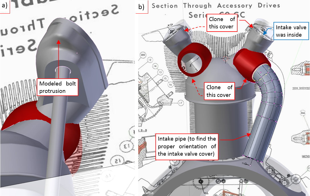
In the next step I cloned the rocker and valve covers onto the opposite side of the cylinder head: over the intake valve (Figure “b”, above). In this first approximation of these parts, I rotated the intake valve cover (marked in red in the picture above), trying to find the proper location and angle of the intake opening. To fit it better, I also placed in this model the intake pipe. I knew, that in the future I will adjust its shape multiple times. That’s why I crated it initially as a simple cylinder, smoothed by the Subdivision Surface and bent along a parent curve using Curve Deform modifier. By controlling the location, rotation and shape of the parent curve I had full control over this pipe.
The intake rocker cover had also a unique feature: two bolts on its front and rear walls (Figure “a”, below). They were intended for mounting around the engine an eventual NACA cowling. (Wright added these bolts on the Army request). For this “conceptual” stage of the modeling, I decided to add the bases of these bolts as a separate part. (Because I expect that I will move/modify shape of this element many times, before I reach the result that matches the reference photos). I will eventually join it with the cover (and add appropriate fillets around its edges) when it fits well.
In the next step I transformed the clone of the intake cover into a completely separate object (marked in blue in Figure “b”, above). I also added the bolt bases around the exhaust and intake openings. (As you can see in the figure above, there are four of them on the exhaust cover, and three on the intake cover). Initially I created these bases as separate objects.
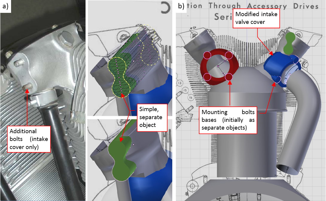
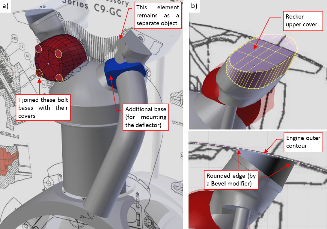
Once I verified their location, I joined these bolt bases with the cover mesh (Figure “a”, below):
I joined these objects by applying a Boolean (Union) modifier. However, after such an operation the resulting edges required some manual “cleaning” (removing doubled vertices and edges).
I also formed an initial approximation of the rocker upper cover (Figure “b”, above). I just placed it over the left rocker. The front contour of this part had to fit the circular contour of this engine (dimensioned on the original installation drawing). I also rounded its upper edge using a multi-segment Bevel modifier, but I can see that this part will require further modifications.
While working with these rocker covers, I discovered that I made a mistake in reading the original blueprints! I thought that one of the exhaust rocker cover elements was a cross-section, while it was oblique view of one of its fins (Figure “a”, below):
On the reference photos I can also see that the bottom pushrod base plane was bent, with sharp side edges (Figure “b”, above). Thus I had to modify accordingly the bottom part of this cover (Figure “c”, above).
Well, such “discoveries” slow down the overall progress of the work, but they are inevitable, if you want to build a close copy of the real object. They happen all the time, as I am collecting growing number of the reference photos. In fact, I have measured that I spend at least half of the overall time on analyzing the photos. (Sometimes I also sketch on a paper the most complex shapes, before I start to model them in Blender. These sketches help me to better “understand” the objects that I want to recreate). The complex details of the cylinder head are often obscured by the fins, which makes this element an extremely difficult case. I am sure that I will identify and fix many of similar mistakes in the nearest future. For example: I will shift and rotate the cover of the intake valve multiple times, and then have to adjust the intake pipe after each of these updates. That’s why I prefer keeping this cylinder as an assembly of multiple, relatively simple objects. It would be much more difficult to modify this head, if it was a single, complex mesh. (In such a case you would have to care about all of its intersection edges!).
You can check details of this model in the source *.blend file. In the next post I will model the cylinder head fins.
3 Likes
Beautiful to follow and look, well documented an excellent resource for many.
1 Like
Welcome back from the Ice Age…![]()
Good to hear you are back on your desk working on this masterpiece…such an inspiring and awesome job!
1 Like
pafurijaz, tommy 1441 - thank you!
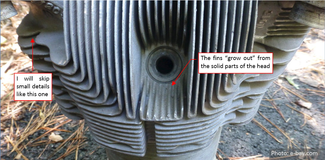
Today I will deal with the complexity of the cylinder head fins:
The fins of the air-cooled cylinder heads are a state-of-art piece of metallurgy:
At the first glance, it is hard to believe that they were cast as a single piece. But when you look closer, you will discover that these fins “grow up” from the solid parts of the head as naturally, as the hair from the head:
Try to imagine the shape of molds used in the production of these parts, and the challenges faced by their manufactures! (See an interesting post about this. It describes production of the R-1830 Twin Wasp cylinders). Basically, modern producers of the heads for the air-cooled aircraft engines use the same technology as eighty years ago.
In my model I will recreate these fins in a somewhat simplified form, as a few separate Blender objects. I will also skip some fine details of their shape (for example the small features that I marked in the figure above). Such a simplification conforms the moderate level of details that I assumed for this model. It is always possible to make a more detailed version of this object later.
I began by forming the “external boundary surface” of the fins. After revising many photos I decided that it has a circular base. This base is combined with a shape extruded from a perpendicular arc:
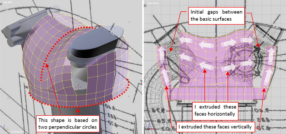
The rocker covers, formed in the previous post, helped me in estimating the shape of this object. In general, the cylinder head fins are not symmetric, since the exhaust valve produces much more heat than the intake valve. Thus there are more fins around this area. Initially I formed the basic shape, leaving gaps around the rocker covers (as in figure above).
In the next step I filled these gaps (figure “a”, below):
In fact, it was sometimes quite hard task that required careful analyzing the shape of the head fins in these areas. Note that fragments of the rocker pushrods were partially “sunken” in this object (as in figure “b”, above).
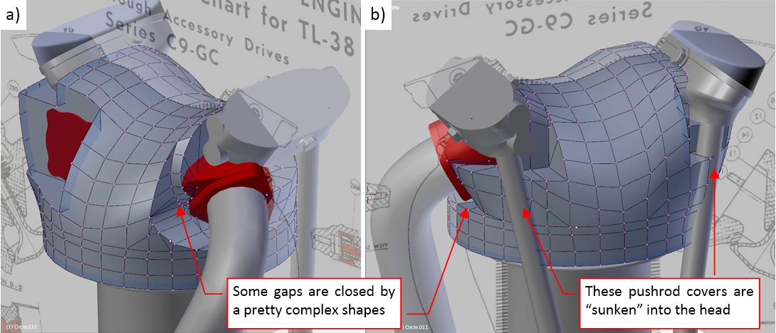
I cut out the areas around these pushrods using the Boolean (Difference) function. To do it, I placed along the rockers two simple “boxes” (figure “a”, below). Then I used them as the “tools” in a Boolean modifier that cuts out from the boundary shape the difference of their volumes (figure “b”, below):
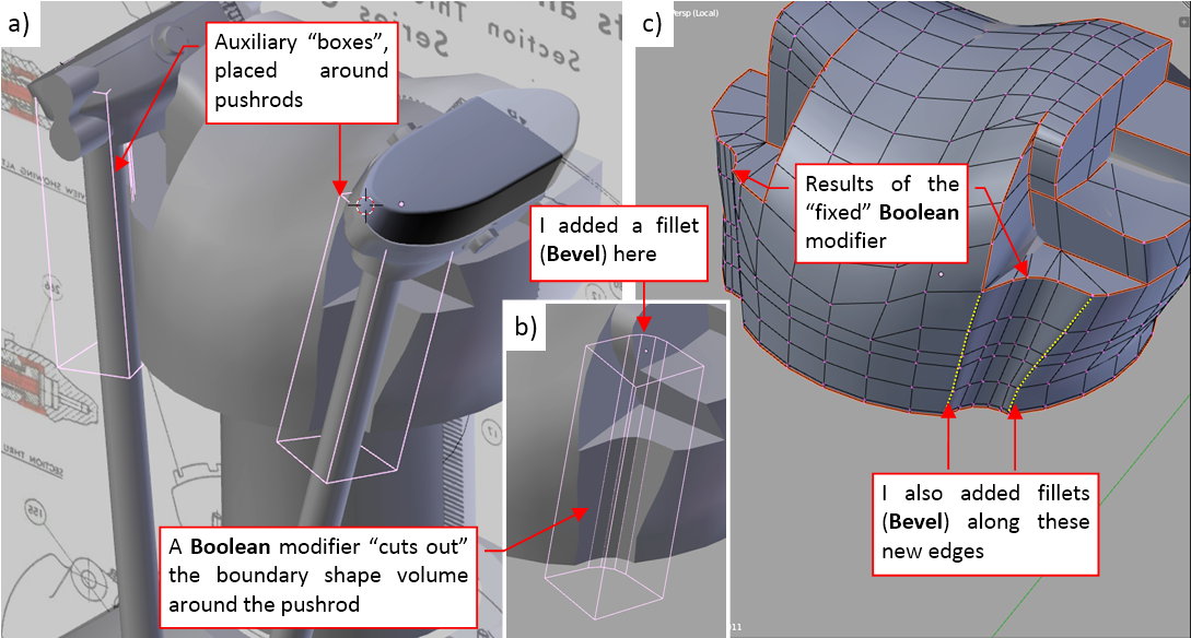
(Note that I rounded the original sharp edge of the “cutting box” using a multi-segment Bevel modifier). Then I “fixed” (applied) results of the Boolean modifier. After removing unnecessary vertices and edges from this area, I obtained the shape shown in figure “c”, above. Finally I dynamically rounded the external edges of this cut out, using a multi-segment Bevel (Weight) modifier.
In similar way I created the hollows for the spark plugs. First I created two objects that have the shape of these cutouts. (As you can see in figure “a”, below, their shape was more complex than the pushrod “boxes”):
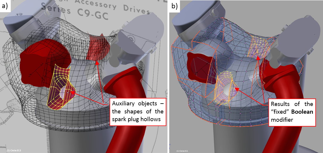
I used these two objects in a Boolean modifier, which I applied to the boundary shape object. Figure “b”, above, shows how this mesh looks like after “fixing” the results of this modifier. I also dynamically smoothed the resulting mesh using a moderate (level =1) Subdivision Surface modifier.
Finally, when the boundary shape was formed, I started to add the head fins. In the simplest case the mesh of a single fin can be just a single square face (figure “a”, below):
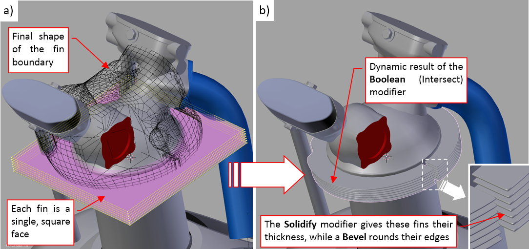
Then I obtained the results shown in figure “b” (above) in a dynamic way, by adding to the fins object a stack of three modifiers:
- Boolean (Intersect) modifier, which uses the boundary object as the “cutting” tool;
- Solidify modifier, which gives the fins their thickness;
- Bevel (Angle) modifier, just to “round” the external edges of the resulting fins;
As you can see above, their cumulative effect is quite interesting.
All what I have to do now is to add to this “fins” object subsequent faces. The “L”-shaped upper fins have somewhat more complex topology:
It is built from a dozen of elementary square faces. I crated the rounded edge in the middle of this fin by adding another multi-level Bevel modifier to the top of the modifier stack. It rounds selected edges – those, where I set the so-called Bevel Weight coefficient to a nonzero value.
Sometimes the results generated by the Boolean and Solidify modifiers look strange. To fix these problems I had to be careful with the normal direction of the newly created mesh faces. Sometimes I even had to add an additional edge loop – because it alters the results of the tessellation that Blender performs for each face.
The R-1820 cylinder head also contains some “M” – shaped fins (as in figure “a”, below):

I built such elements using an outer “U”-shaped surface combined with the inner, flat face (figure “b”, above). The faces of the “U”-shaped surface have their normals directed outside, so the Solidify modifier generates the thick “walls” around it. The two edges at the “bottom” of this “U” are rounded (figure “b”, above), as in the case of the “L”- shaped fin. The inner surface extends a little (by less than the fin thickness) outside the original faces of “U”-shaped surface. After applying the modifiers, this “overflow” creates an impression that both surfaces are joined.
As you can see in figure “a”, below, the final mesh of the head fins resembles somewhat a Minecraft object:
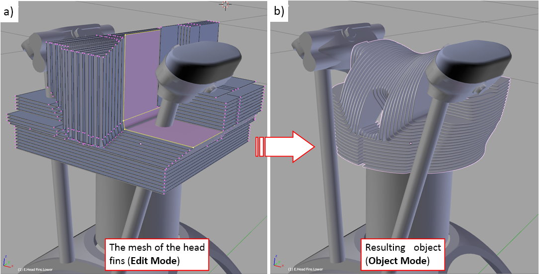
However, when you switch into the Object Mode, in a split second the modifiers transform it into the desired shape (figure “b”, above).
Do not be mistaken by this “smooth” workflow description. In practice I often had to make minor adjustments to the boundary surface mesh, to correct some unexpected effects of the Boolean modifier. Fortunately, the mesh of each fin is disconnected from the others, so all these issues appeared gradually, and I was able to resolve them in a systematic way. I had also made other adjustments: for example, in the middle of the work I discovered that the spacing between the fins was 0.215” instead of 0.220”. (I know that this distance seems extremely small, but for the 30 fins in a row, it really makes a difference!). Thus I shifted - vertically or horizontally - about two dozen fins. Fortunately, the Boolean modifier took care for the resulting adjustments in their shapes.
What’s more, it occurred that these dense, evenly spaced fins act as a kind of additional reference grid. While forming them, I found and corrected some inaccuracies between the fins and the valve and rocker covers.
You can check details of these fins in this source *.blend file. The model starts to resemble the real cylinder, but it still lacks many details. I will describe them in the next post.
1 Like
I can’t wait until you start researching the precise species of flying bugs which would have got squashed against the front of the engine in the relevant theatre of operations, and conducting experiments into exactly how their carapaces would have deformed on impact. 
1 Like
I agree with you about the scale plans! I’m used to it from some 1800’s ironclad models I made. I didn’t know it also applied to something from the 20th Century.
Gumboots: this is an temptation  , but in my new “reporting” post you will see that sometimes I also made some trade-offs, and simplify the things. The assumed LoD rules!
Tea_Monster: I think that the reason for this situation is really simple: when you are a professional writing another book about such historical/technical stuff, you are just using information from other books. The same for the 2D drawings (“the paper endures everything”). In particular, you often just accumulate the errors made by the others. All these differences emerge, when you try to built a spatial replica. In such a case, if you have also enough time, you can critically review the sources and slowly come closer to the real thing. Usually, the only one who has such amount of time is a hobbyist. The professional has too many deadlines.
1 Like
In this post I will finish the first cylinder of the R-1820 “Cyclone”. It will be the “template” object, which I will clone eight times around the crankcase when I finish the other parts of this engine.
Although in my previous post the cylinder head received the full set of its cooling fins, it still lacks some details. One of them are the reinforcements of the valve covers:
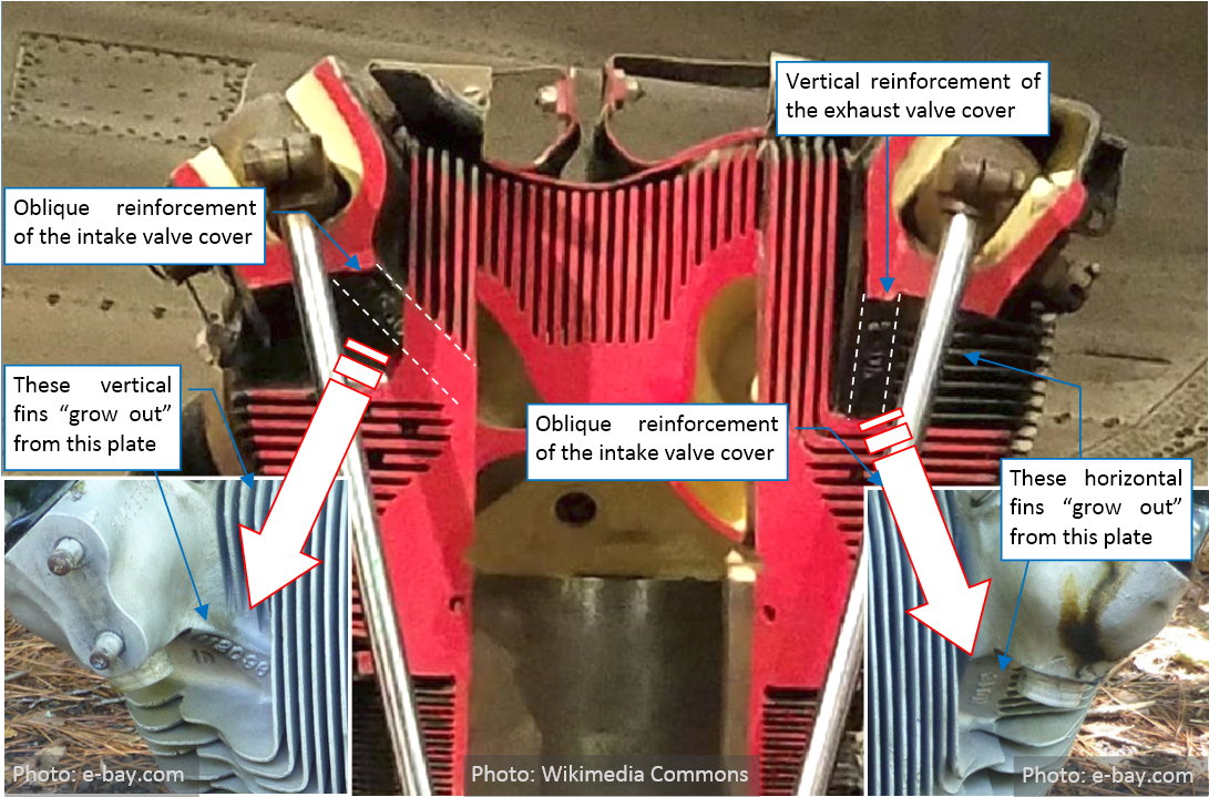
As you can see, these reinforcements break the symmetry of the left and right valve covers. Both of them resemble a thick plate, but one is oblique, while the other is vertical. They are not the most prominent features of this cylinder head, and it took me some hours to determine their probable shape. Finally I classified them as the secondary features of the covers, which I have to recreate, for the assumed level of details.
First I formed the oblique reinforcement of the intake valve cover. I extruded it from the existing mesh:
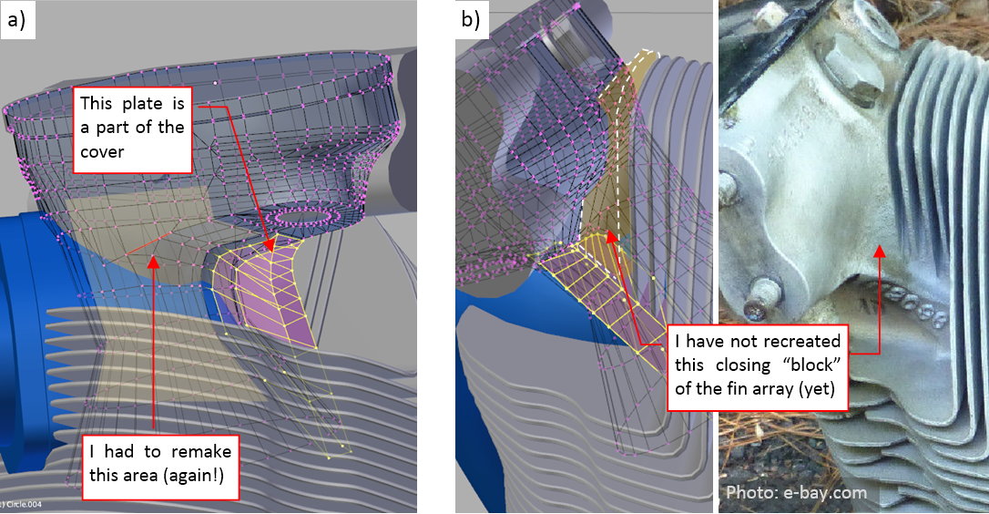
When you compare this mesh (in Figure “a”, above) with the last picture in my last-previous post (its Figure 85‑11), you will clearly see that I had to remake this shape again. (I was wrong, then). At this moment I declined to create the last “block” that closes the array of the vertical fins at this cover (Figure “b”, above), because it would be too difficult to merge such a feature within the current mesh. I will come back to this issue later in this post.
In the case of the vertical reinforcement of the exhaust valve, I encountered similar problem: it would be quite difficult to extrude such a shape from the existing mesh. However, this time I decided to make it as a separate object:
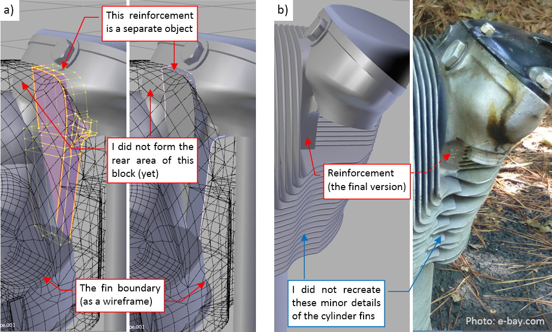
The next element that I recreated is the top cover of the rocker (Figure “b”, below):
After some initial trails, I decided that the previous, simplified version of this element that I made some weeks ago is useless. (You can still see it in Figure “b”, below). Thus I started a new top cover from the scratch. I formed it using the same reference drawings that I used for the main rocker covers (Figure “a”, above). The fillets of this shape (I marked them in yellow) are created using a multi-segment Bevel modifier. However I had some troubles with the radius of the upper fillet (Figure “c”, above). It occurred that the Bevel modifier can alter the fillet radius along the rounded edge. What’s worse, I could not obtain the larger radius at the higher corner of this cover, because their proportions and sizes were restricted by the height of the cover shorter side (Figure “c”, above). Well, the difference was not so big, thus I accepted it.
In the next step I prepared four conical shapes in the places where this cover had recesses around the bolts (Figure “a”, below):
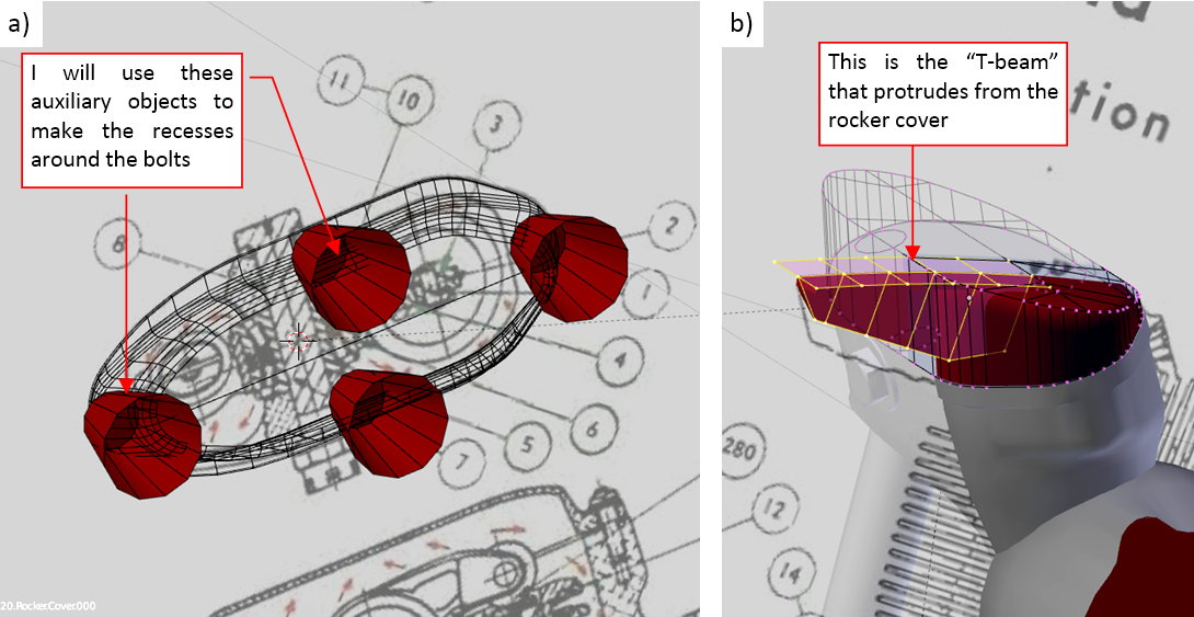
In the “old” object, still located on the top of the rocker cover, I also created a perpendicular “T-beam” (Figure “b”, above). I formed it there, because I needed to use the outer, circular contour of this engine as the reference. It was just prepared for later.
Then I started to create the recesses around the bolts. After applying each of the Boolean modifiers I had to “clean” this mesh by removing the extra vertices and edges (Figure “a”, below):
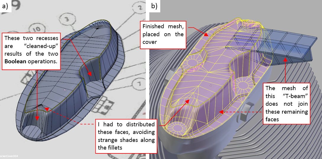
Then I spent significant amount of time on improving the shape of the fillets around these recesses (initially they were in a really bad shape). Basically, I had to disperse the fan-like edges from the forward recess along the mesh, and add some new “middle” edges (Figure “b”, above). Finally, I placed this rocker top cover on the cylinder head and joined it with the “T-beam” object that I had prepared some steps before. Note that I left these two meshes disconnected – it looks quite good as it is (especially in black – see figure below). Joining faces of this “T-beam” and the rest of this cover would require significant amount of work.
Comparing to these top covers, the details of the cylinder barrel were easy. In the real R-1820 its fins were made separately, from steel rings. I created them from a quarter of such a ring:

I just used a Mirror modifier (along X and Y axis) to convert this mesh into a full ring, then multiplied it down along the barrel using an Array modifier. Finally I added the Solidify modifier, which gave these plates some thickness.
I also used a large-radius multi-segment Bevel modifier to profile the cylinder base (as in figure above).
Finally I added the first bolts to this engine. Each of these objects is a clone of the same mesh. Initially I prepared two such meshes: the classic nut for the rocker top covers, and the massive head for the bolts around the cylinder base (Figure “a”, below):
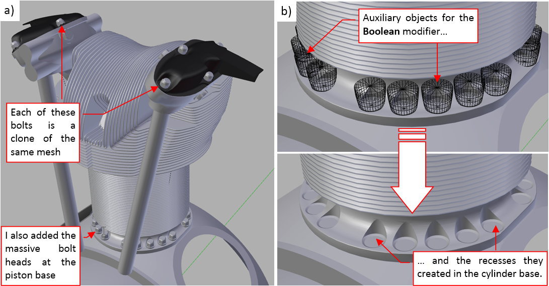
I also recreated recesses in the cylinder base around these bolts. I made it using an auxiliary object and a Boolean (difference) modifier (Figure “b”, above). (In fact, to make the edges of these recesses more regular, I had to alter a little some faces of these auxiliary objects).
The last element of the cylinder was its upper deflector. Basically, this is just a piece of the sheet metal, “wrapped” around the cylinder head:
Although most of this deflector surface lies in the “invisible” back area of this engine, I decided to recreate it as a whole – just for the eventual future use. (In fact, the most difficult part was to determine the approximate shape of this part). It was made from a single smoothed (by the Subdivision modifier) mesh surface. The vertical reinforcements on its sides are created as separate objects, also made from a single surface. Additional Solidify modifier gives them a non-zero thickness. Because this is the “invisible” zone of my model, I did not recreate such minor details as the bolts and rivets, here.
In general, this deflector was the last part of the cylinder. However, you never know when you find something new and will have to modify your model.
I finished this cylinder about two months ago, and then worked on the other parts of this engine. (Yes, my reports are always a few weeks late). After a month I finally decided to recreate the closing block of the fin array at the intake cover (marked in red in Figure “a”, below). This time I made it as a separate object, to avoid tedious work of rounding all of the eventual intersection edges. I also looked for more reference pictures. One day in May I found additional detailed photos of the R-1820 cylinder head in a certain e-bay auction. When I compared them to my model, I discovered that my cylinder is missing one fin at the intake cover:
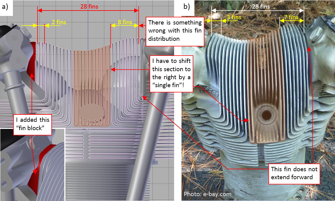
(There were three such fins in the photo, while my model had only two). The new photos quickly revealed my error: I have to shift the forward faces of nearly all existing vertical fins to the right! (To the next fin).
Such a movement of the 26 fins will create space for additional “shorter” fin on the left and discard one fin on the right. It also will shift the central segment of these fins that contains the hollow for the forward spark plug.
Fortunately, the structure of my model allows me to do such a modification in a relative easy way. (That’s why I hold myself in duplicating this cylinder to the latest stage of this project, and using in every of its objects as many modifiers as possible). I have introduced all these updates to the latest version of this R-1820 model, thus you will not find them in the example file that accompanies this post. (They will appear in the file that accompanies one of the future posts).
How I did it? First, I modified the shape of the “fin boundary” object, which I use to the Boolean modifier to “cut” the fins (Figure “a”, below):
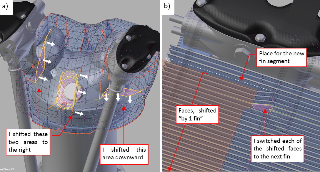
Then I shifted the “raw” faces of the fin mesh to the right by one “fin module” (0.215”). When I did it, I started switching these shifted faces to the adjacent fins (Figure “b”, above). Finally I dropped the rightmost fin and added one fin segment on the left.
Figure “a”, below, shows my results, while Figure “b”, below, is the picture of an authentic R-1820 head:

The most obvious difference is the certain “angularity” of my model: it lacks many of the soft fillets and intermediate surfaces that you can see in the original head. This is the price for the relative simplicity and moderate polygon count. (The final model of this engine will have about 500 thousand faces). Making a more detailed version of this head would require much more time, and (at least) four times more faces in the final model.
However, I can also see various minor differences in the area around the exhaust (I marked it in figure above using a dashed line). It seems that I should shift the exhaust base to the rear, because you can see it on the photo, while it is hidden under the fins in my model. This is strange because I read the precise location of the exhaust opening from the explicit dimensions on the original installation drawings. I have also found another minor difference between this photo and the original Curtiss-Wright drawing. Thinking about it, I realized that I am using reference drawings from 1942, while the head in this photo comes from a B-17G (according the e-bay auction). This means, that it was produced no earlier than in 1944. It may happen that I found minor differences between various R-1820 production series. All in all, they appear on the rear part of the engine, which will be invisible in my model. Thus I decided to continue without fixing these findings.
Figure below shows the current state of the cylinder model:
You can examine my model in this source *.blend file. Just remember that this is the earlier version, saved in March (before I shifted the forward fins). In the next post I describe my work on the crankcase details. After this I will recreate the spark plugs, ignition harness and the side deflectors (between the cylinders).
3 Likes
In my previous posts (published in May and June) I focused on the R-1820 cylinder. I think that it is the most difficult part of every air-cooled engine. Since that time I have made a significant progress, which I will report during nearest three weeks.
Let’s start with the rear section of the crankcase (behind the cylinders). Do you know how difficult is to find a decent photo of this area? The original pictures from the “Cyclone” manual are of moderate quality:
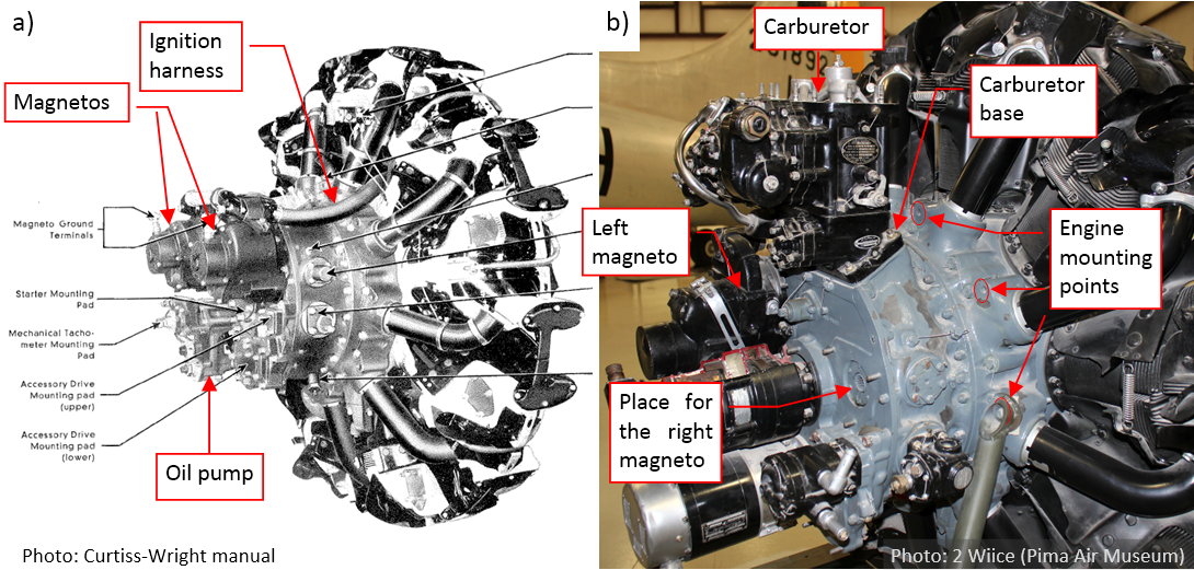
The modern photo (Figure “b”, above) reveals more details. In general, it looks that the rear part of the crankcase is formed from two cylindrical segments. The intake pipes extend from the first (i.e. forward) of these segments. (There is a centrifugal supercharger inside). The upper part of the last segment contains rectangular air scoop, which also provides the mounting points for the carburetor (Figure “b”, above). The rear wall of this segment forms the base for various auxiliary aggregates: magnetos, oil pump, starter, etc. As you can see in Figure “b” (above), aggregates from the R-1820 exposed in the Pima Air Museum differ from the manual photo (Figure “a”, above). I think that such equipment could be used in the B-17s. On this photo I also finally determined an important feature of the R-1820 geometry: its mounting points. (They are dimensioned on the installation drawings, but I had to find them among all these nuts and bolts that you can see on the crankcase).
I think that this rear part of this engine is much more complex than the forward section. Fortunately, it is invisible in my model (I am not going to open the engine cowling panels, at least not at this stage of the project). Thus I recreated them just as placeholder “blocks” (see figure below). In this simplified form they will allow me to determine the details of the SBD engine cowling geometry:
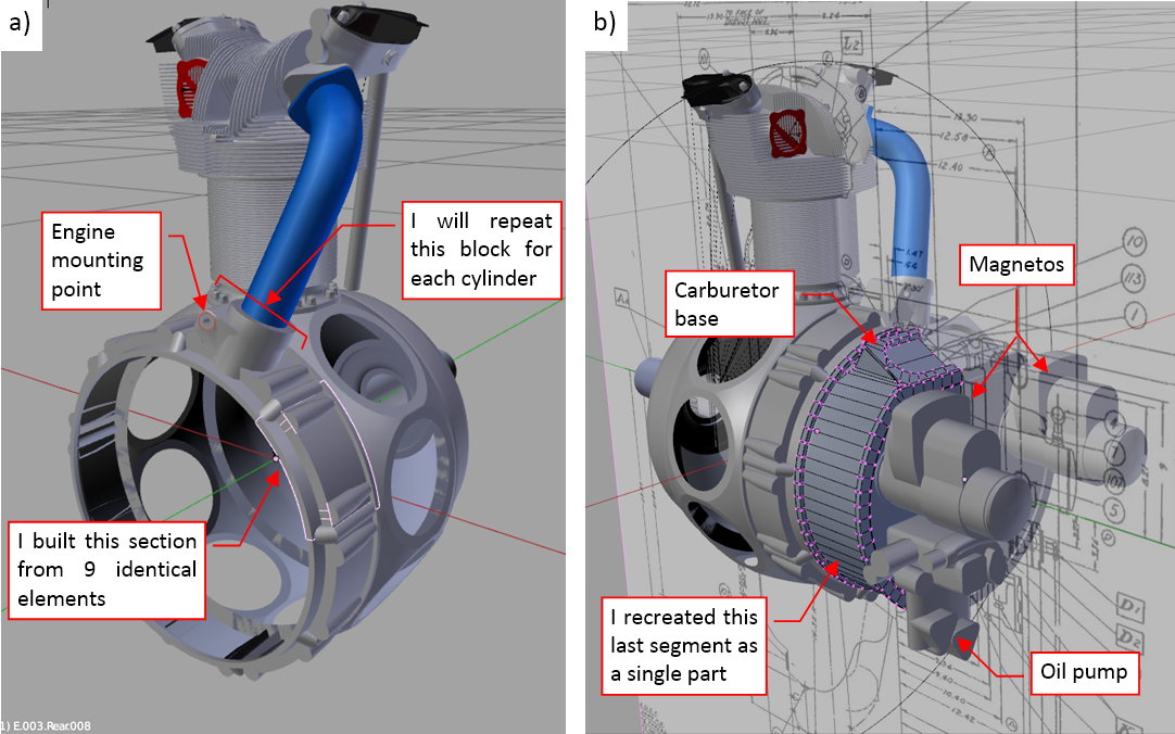
Once I saw these details on the photos, I was able to properly interpret the original installation drawings from the Curtiss-Wright manual. I recreated in the simplified form the intake pipe base (Figure “a”, above). I will repeat these blocks for every cylinder. (I built this crankcase section from nine identical parts). Note the hole for the mounting bolt on the left side of the intake pipe. I just placed it there as a reminder for myself. The last crankcase section is created as a single (mirrored) part (Figure “b”, above). I placed the simplified magnetos and oil pump on its rear wall.
In the next step I recreated there the details of the pushrod bases in the front of each cylinder:

The rim of the forward crankcase is usually obscured by the ignition harness. I managed to find some photos that show this part. They reveal that there is a cylindrical “strip” around this rim (Figure “a”, above), which forms the base for the pushrods. The outer diameter of this “strip” matches the rim diameter of the crankcase main section (the section that forms the cylinder bases). It is larger than the diameter of the conical part of the forward crankcase. The forward edge of this strip has characteristic “stair” shape (Figure “a”, above). This shape repeats in the front of each cylinder. Every “step” of these “stairs” matches the base plate of one of the pushrods, or forms a bolt head base.
As I described it in the first posts about the R-1820, I formed this forward section of the crankcase using nine identical segments (clones), placed in the front of each cylinder. Thus I just had to recreate this strip in the mesh of a single segment, and Blender automatically repeated it around the crankcase rim (Figure “b”, above). In this mesh, I used a multi-segment Bevel (Weight) modifier to round some of the newly created edges. (I have some troubles with the intersecting beveled edges, here. Finally I decided to use the Bevel modifier for the “meridian” edges, only. I created the gentler, “parallel” fillets manually, placing 3 or 4 new edges at the rim strip base).
When I reproduced the “stair” forward edge of the pushrod bases, I discovered that:
- For each cylinder, one of the pushrods is shifted forward. (This is a norm for every classic radial engine, because each of these two pushrods follows different cam. One of them uses the intake valve cam, while the other uses the exhaust valve cam);
- The pushrod bases were closer to each other than they depicted them in the original installation drawings from the Curtiss-Wright manual. (It could happen, because this was not any important, “dimensioned” element of these drawings);
I moved accordingly the pushrod bases close to each other, and then I discovered that they no longer fit their troughs in the cylinder head (Figure “a”, below):
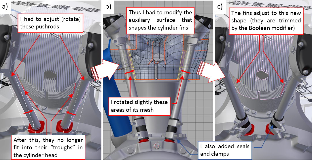
Fortunately, the shape of the head fins is still controlled by the surface object (via a Boolean modifier). All what I had to do was a minor adjustment of its mesh (Figure 88‑4b). Then Blender took care for the fin shapes (Figure “c”, above).
As you can see (Figure “b”, “c”, above), I also added to this model the pushrod seals and clamps. All of these details are clones (they share single mesh). These clamps will be useful in other places of this engine.
Another engine element hides among the lower cylinders (5 and 6): this is the oil slump:

While the forward part of the oil slump appears on many photos (as in Figure “a”, above), all what I found about its overall shape were: two pictures from the manual (Figure “b”, above), and the side contour on one of the blueprints. However, certain features became obvious, when you place this part into the model. The recesses on its sides fit the adjacent cylinders (Figure “c”, above), while the Y-shaped “tail” bypasses the vertical intake pipe that belongs to cylinder 5.
I formed oil slump using subdivision surfaces. To keep the shape of the front crankcase as simple as possible, I modeled the oil slum base as a separate object. Its external edges blend smoothly with the two adjacent crankcase segments. (These segments are separated along the engine centerline).
On the forward part of the oil slump you can see a prominent engine data plate. I will recreate this detail later, together with similar elements that occur in the cockpit. (They will require a separate texture).
On the opposite side of the crankcase there is a more exposed feature: propeller governor base:
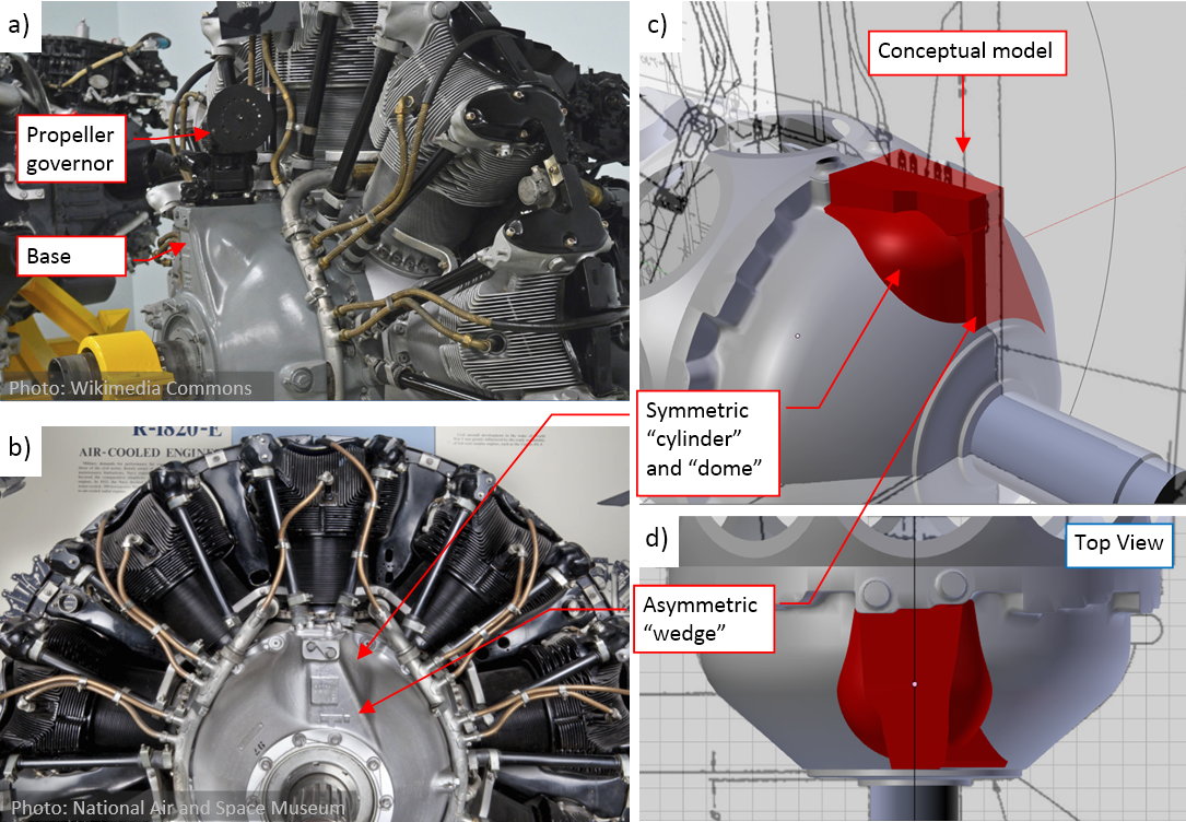
In general, its shape is a combination of symmetric cylinder and dome with an asymmetric “wedge” (Figure “b”, “d”, above). To find the proper proportions of these objects, first I prepared their simplified, conceptual model (the red blocks in Figure “c”, “d”, above). The most “sensitive” elements here are their intersection edges, especially on the oblique, left side of the “wedge”. I tried to obtain similar shapes of these curves to those visible on the photos. (However, in the real crankcase these edges are “soften” by the fillets. It is more difficult to determine their exact shape).
Finally, when the conceptual model was close enough to the original, I used it as the base for the final version:
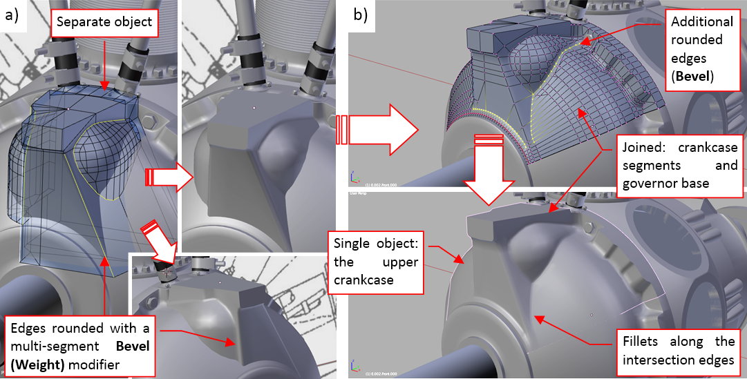
First I joined the “cylinder” and “wedge” into single object, and added fillets (multi-segment Bevel modifier) along their intersection edges (Figure “a”, above). Then I joined the three upper segments of the forward crankcase with this propeller governor base (Figure “b”, above). It created additional intersection edges, which I also rounded using the same Bevel (Weight) modifier. Note that I did not “smooth” this surface with a Subdivision Surface modifier: it was dense enough without it.
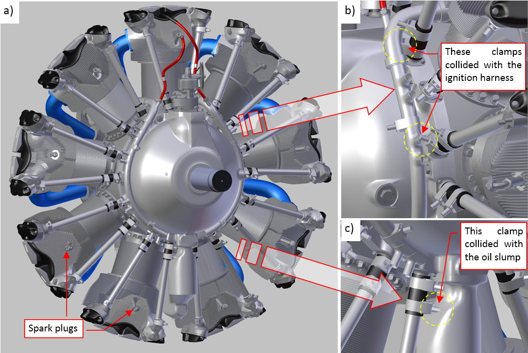
The next element of the engine is the ignition harness. Figure below shows its rear part:
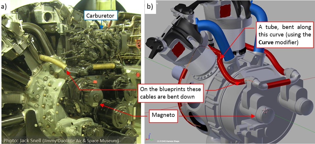
In fact, this part will be invisible in the final Dauntless model. I recreated it because I just do not like to “suspend objects in the air”. Still, while fitting this engine into the airplane, the simplified versions of these invisible parts can give you a valuable hint about potential collision/intersection. The harness in the engine from the Jimmy Doolittle Air & Space Museum (Figure “a”, above) seems to be rotated upward on the magnetos. I recreated in the reversed position (Figure “b”, above), as in the manual (see the first photo in this post).
The manifold of the harness is a simple tube, bent along the curve that controls its shape. (I used here the Curve Deform modifier). The forward part forms a 300⁰ arc around the crankcase:
I already placed along this manifold the bases for 18 individual spark plug cables (Figure “b”, above). At this moment I recreated the first pair of these cables, for the topmost cylinder. Each of these two tubes has its own deforming curve. As you can see (Figure “c”, above), I also recreated the spark plugs and the clamps that attach these cables to the pushrods. I will recreate the remaining 16 cables in the next post, when all of their cylinders will be in place. (Each of these cables will be bent along a slightly different shape). There are also four mounting brackets (Figure “d”, above) that attach the ignition harness manifold to the crankcase.
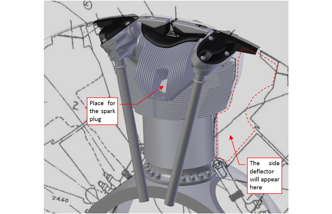
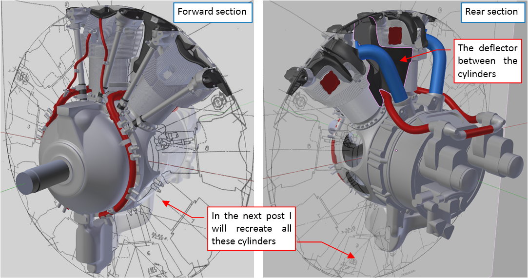
I also recreated the deflector plates, mounted between the cylinders:
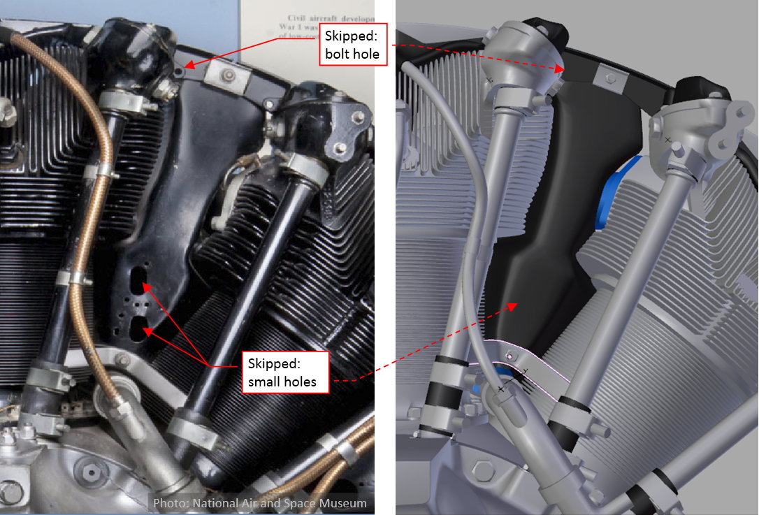
I decided to skip (simplify) some of their features that will be less visible under the NACA cowling. Thus I omitted the bolt holes at the cylinder sides, and various small holes in some of these plates. (The purpose of the two holes visible - in Figure “a”, above - will become obvious in the next post).
Figure below shows the current state of this R-1820 model:
I will finish it in the next post.
You can examine the model depicted above in this source *.blend file. Just remember that this is the earlier version, saved in May (before the correction of the the forward fins, which I described in my previous post).
2 Likes
I did a low - medium res for this motor 2 years ago
but not a the level of details you are at !
one note this engine was also used on tanks
so check on military forum or rebuilt of engines
you might find more photos
good luck
happy cl
RickyBlender - thank you!
However, to properly interpret these details, first I have to learn more about subsequent “Cyclone” versions (to not mix elements from various engines into a non-existent one). I will write more about it in the next post.
In this post I will finish all the remaining details on the front of the R-1820 engine. (As I mentioned in earlier posts, this model is intended for the outdoor scenes, with closed cowlings. That’s why I recreated the more complex rear part in a simplified form, just to check if it fits properly to the airframe).
One of the most exposed “Cyclone” details is the variable-pitch propeller governor:
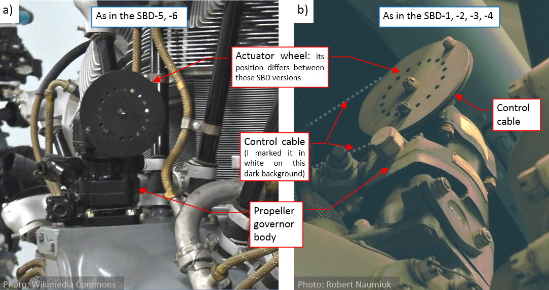
This is an additional unit that controls the pitch of the Hamilton-Standard propeller. (It controls the oil pressure, which determines the actual pitch of the propeller blades). You can find it in every aircraft, but it is often dismounted from the “standalone” engines, presented in the museums. The large wheel at its top is used as an actuator attachment. The actuator can be a pushrod or a cable from the cockpit. In the case of the SBD (and many other WWII aircraft) it was a control cable (Figure “b”, above). The engine depicted in Figure “a”, above is a standalone museum exposition, thus it lacks such a cable.
Analyzing the photos, I slowly recognized that this governor was mounted differently in various Dauntless versions. In the later SBDs (SBD-5, -6) it is placed in the front of the topmost cylinder, and its actuator wheel is on the left side (as in Figure “a”, above). In the earlier versions (SBD-1, -2, -3, -4) it is mounted between cylinder 1 and 2 (as in Figure “b”, above). Let’s focus on the later versions first, because I have more its photos. I could even find the propeller governor base on one of the original installation drawings (Figure “a”, below):
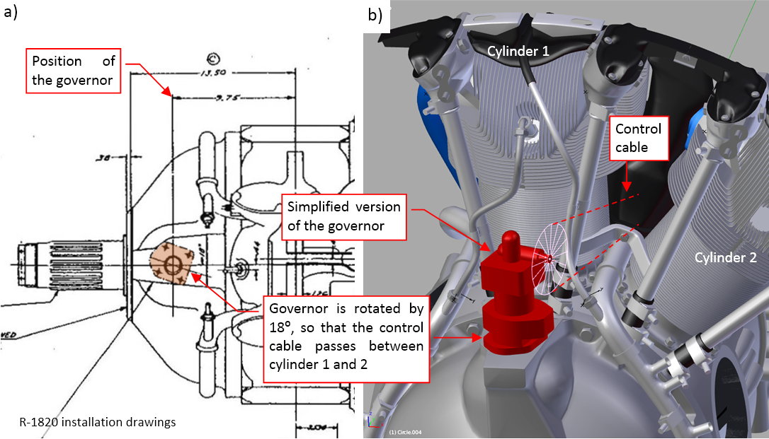
This drawing shows, that the governor was rotated by 18⁰. The reason for this unusual arrangement became obvious when I fit into the model the first, simplified version of this object. This rotation directs the control cables between cylinders 1 and 2 (Figure “b”, above). Do you remember the two small holes in the deflector depicted on the second-last photo from the previous post? They were made just for this cable.
However, I could not determine the ultimate shape of the governor unit. Most of the photos that I had looked like those that I show in the first picture of this post. They were taken at unusual angles, or the object was in black, which obscured its details. I was only able to determine, that there are several versions of this part, which differ in important features (for example, they have different number of outlets). It seems that this is a third-party component, delivered by independent vendors. In desperation, I looked for it on the e-bay, where I ultimately found a decent photos:
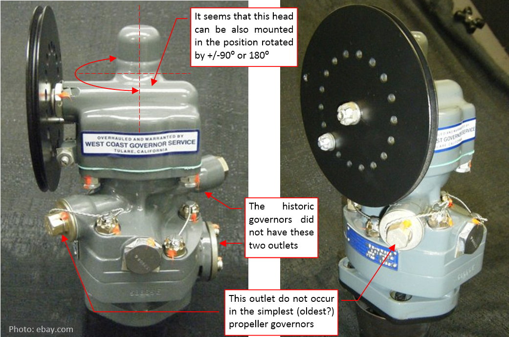
The version on the pictures above was widely used in the aircraft from the post-war period. It has two additional outlets, which did not exist in the propeller governors used during WWII (at least not on the photos that I have). Anyway, it still resembles the governors that you can find on the historical pictures. Using it, I was able to build a more detailed model:
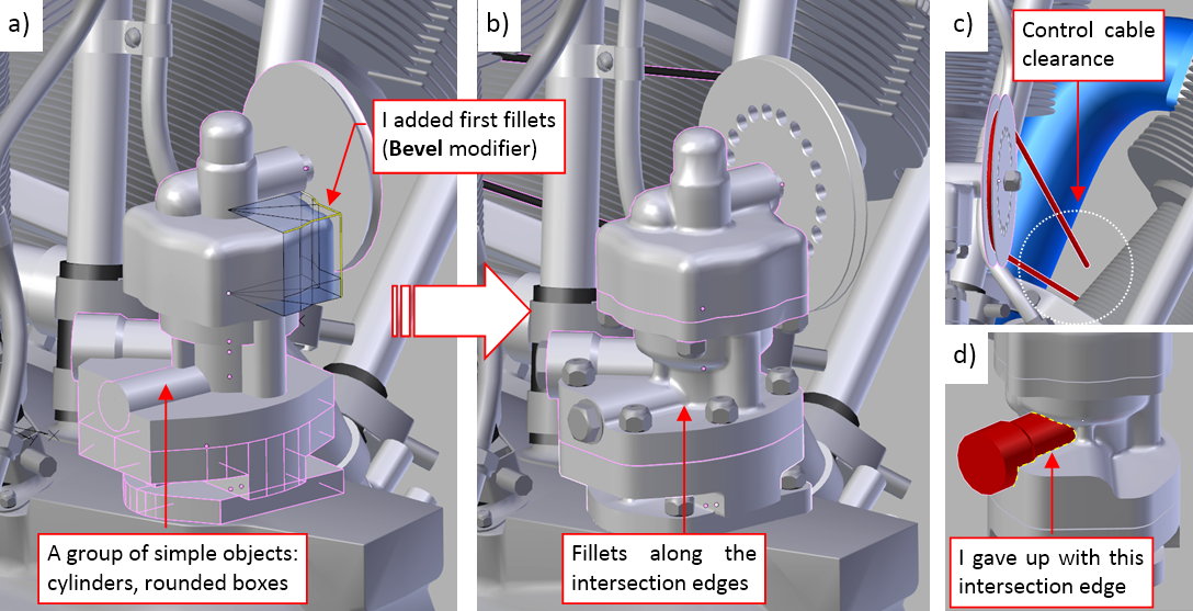
First I recreated the governor shape using a group of simple “blocks”: cylinders and boxes with cylindrical sections. Then I adjusted their proportions and positions, so that they resemble the original object. Finally I started to join these objects (using Boolean (Union) operator), and rounding their intersection edges using a multi-segment Bevel (Weight) modifier (Figure “a”, above). I set up a large “nominal” radius of this Bevel modifier (1.3”). Then I controlled the radii of individual fillets by assigned fractional bevel weights to their intersection edges.
I practiced that you can set these fractional values in the Mean Bevel Weight field of the Edge Data section, at the top of the View>Properties region. (The region at the right edge of the 3D View window that Blender shows/hides when you press the [N] key).
You can see the final result in Figure “b”, above. Note that I had to check the control cable clearance behind the deflector (it has to pass by the intake pipe of the cylinder 2 – as in Figure “c”, above). However, the fillets in Blender are far from the ideal: I gave up with the edge of the rear outlet (Figure “d”, above). To not spoil the previously rounded edges, I had to leave this cylinder as a separate object, just attached to the main body by the “parent” relation. (Fortunately, this is a less visible detail).
To round this edge, I should sculpt it in a mesh that is “dense” enough (i.e. has enough faces in this area). Such a labor-intensive solution does not match the level of detail assumed for this model.
The next detail is the elevated edge around the valve timing inspection hole. You can see it on the front crankcase section (Figure “a”, below):
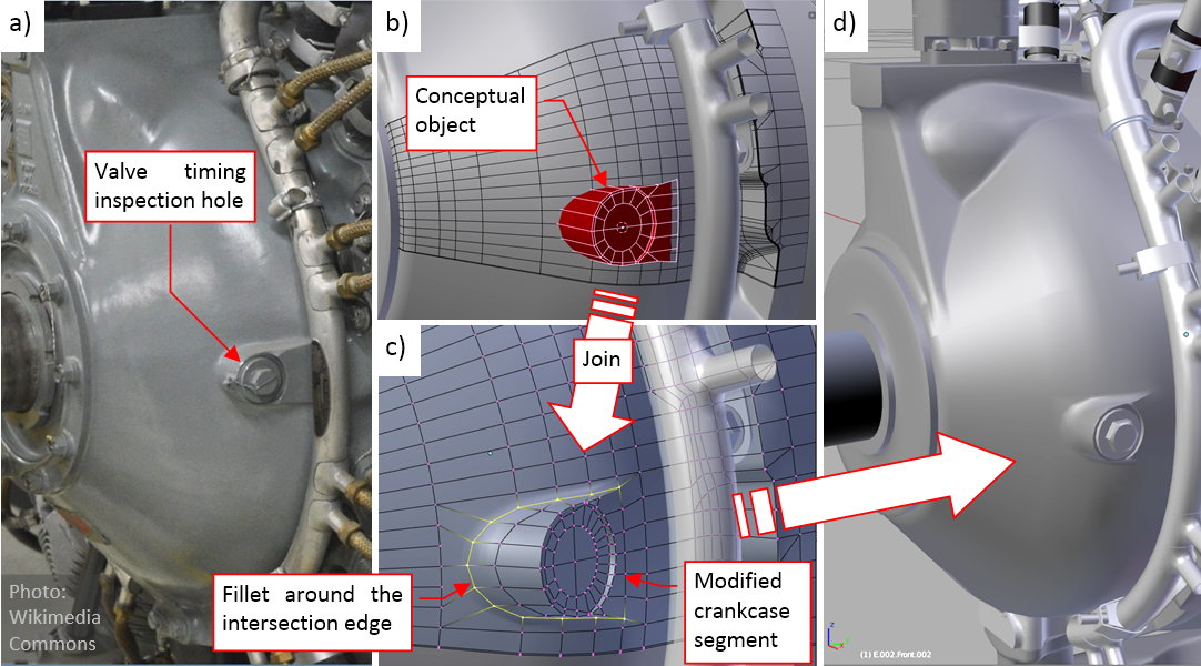
As usual, I started with a simplified, conceptual object (Figure “b”, above). It allowed me to adjust the proportions and size of this feature, as well as the mesh topology. Then I joined it with the corresponding crankcase segment, and rounded the newly created intersection edge with a multi-segment Bevel (Weight) modifier (Figure “c”, above). You can see the final result in (Figure “d”, above).
Finally, it is time to populate this engine with all nine cylinders. I delayed this operation to the end, because I was going to duplicate these objects as the clones (i.e. new objects that share the same mesh). After such a multiplication, if I discovered that these cylinders lack a certain detail, I would have to copy it nine times. That’s why it was better to wait with such a multiplication until it seemed that none of such modifications is needed. However, in May I received an invaluable suggestion from Jeff (pzzs7f, in this post) that I should try the so-called group instances. I did it in following way:
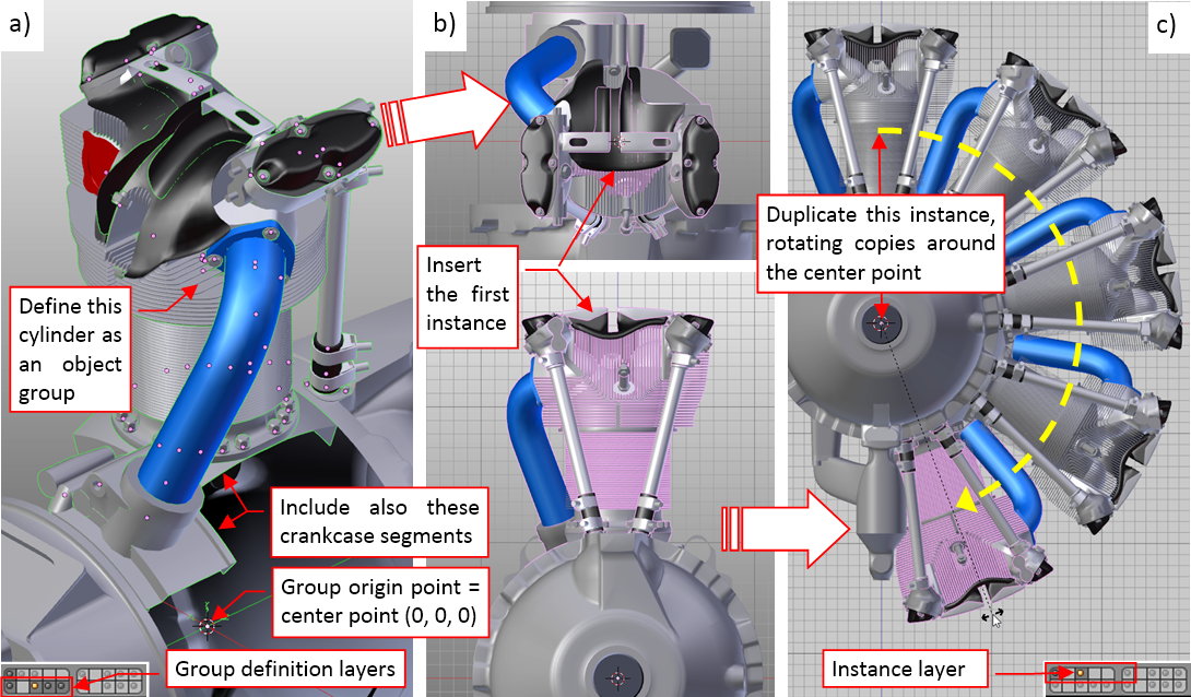
First I placed all the cylinder elements on layers 13, 14, 15, then declared them as an object group (Figure “a”, above). (I did it using the Object>Group>Create New Group command. Blender highlights the objects that belong to the same group with a green outline, which you can see on this picture). I named this group G.G05.Cylinder. Note that it also contains the crankcase segments located around the cylinder (elements from layer 11). Beware that Blender assumes the center point ([0, 0, 0] in the global coordinate system) is the eventual origin point of an object group. Thus place your source objects accordingly in the space around this point.
When this “group definition” was ready, I turned its source layers off, set the 3D cursor to the engine center point, and in the top view I inserted the first instance of this group (Add>Group Instance). You can see it in Figure “b”, above. (Accidentally, it is located in the same place in the space as the source objects, but you could insert it anywhere). When you examine this cylinder, you will discover that this is an Empty object, which contains reference to the G.G05.Cylinder object group.
To “populate” this engine, just create clones of this first instance, and rotate them around the center point by 40⁰, 80⁰, 120⁰, and further angles. You are placing in this way the subsequent cylinders in their locations (and rebuilding the mid- and rear-crankcase, as well). Figure “c”, above, shows how it looks like. Note that I have placed all these cylinder instances on a different layer: 3.
Such instances of an object group are a great tool in dealing with repeatable machine parts. When you add an additional object to this group, it immediately appears in all cylinders. When you remove an object from this group – it disappears from all instances (although it still exists on one of the source layers). This means that I could use these instances earlier, without worrying about adding the remaining details! Well, in my next model I will recreate the cylinders at least in the middle of the project. It is always better to see the whole engine.
What’s more, Blender optimizes the way it displays and renders such instances: note that its Faces/Verts/Tris counters do not take into account their meshes!
Figure “a”, below, shows all nine cylinders in place. Note, that each of them contains also the spark plugs. After this “multiplication”, I carefully examined each of these group instances, looking for eventual intersections with other objects:
As you can see in Figures “b”, “c”, above, there are just few of such collisions, caused by the clamps on the pushrod seals. I have tried to rotate these clamps, hoping to find a universal “neutral” position that does not collide with anything. Finally I gave up: I excluded clamps from the object group and copied their clones around the engine. Then I could rotate each of them separately around the pushrod, fixing every collision that I had found.
I also recreated the side deflector as another instance group:
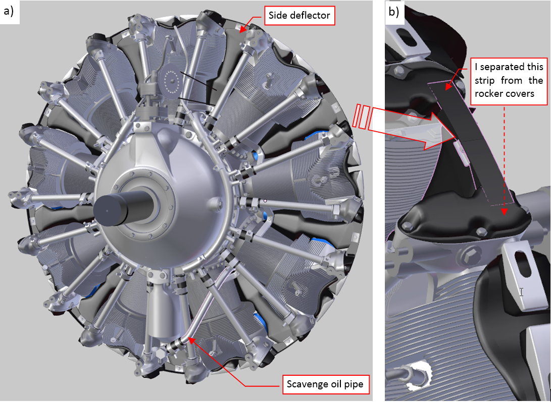
I named this group G.G10.Deflector. Its source objects are located on layer 16, while the group instances – on layer 6. At this moment all the deflectors are identical (for example, they were mounted in this way in the “Cyclones” used in the B-17s). For such an effect I could simply add the side deflector into the cylinder group (as I did for the cylinder top deflector). However, in the SBDs there were two gun troughs in the cowling, on both sides of the topmost cylinder. Thus I decided to define this deflector as another group, because in the future I will have to replace the two topmost deflector instances with modified clones. For the same reasons I “extracted” the side beam from the rocker cover into a separate object (Figure “b”, above).
Looking at Figure “a”, above, you can find some additional parts: a few dozens of new bolts, as well as the scavenge oil pipe. (This pipe connects the bottom of the oil slump with the pump in the rear).
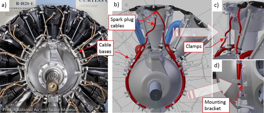
Finally I added the last remaining detail: spark plug cables:
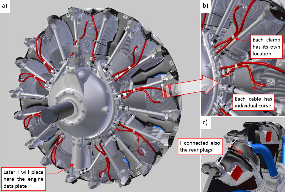
As you can see, the cables occur in pairs. In each pair there is a longer and a shorter cable. The longer one connects the rear spark plug (Figure “c”, above). (I know that this is the “invisible” area, but I could not resist the temptation to recreate this detail). The shorter one connects the front spark plug (Figure “b”, above). All cables of the same length (short or long) and their terminating nuts share the same mesh (they are clones). However, each of them has its own shape, because their Curve Deform modifiers refer to their individual curves (Figure “b”, above). I copied these curves around the crankcase, and then introduced minor modifications to their shapes. Also the clamps that attach these cables to the pushrods are individual clones. I introduced some random variations to these shaping curves and the positions of the cable clamps that attaches them to the pushrods. In this way they resemble the original, manually connected cables. The only missing element in this model are the engine data plates. I will recreate them later, together with the cockpit details. (They require a dedicated, high-resolution texture).
The engine seems to be complete. (Of course, for the assumed level of details: the rear crankcase sections and their equipment are recreated in the form of simplified blocks). I will fit it into the cowling, then cut out the deflectors below the gun troughs.
I zoomed the data plate on one of my reference photos, and found that this is the R-1820-60 (the version used in the SBD-5: 1200hp for takeoff). All the manuals and blueprints that I have collected describe this or one of the later “Cyclone” versions. Thus I can conclude that the R-1820-66 (the version used in the SBD-6: 1350hp for takeoff) seems to be identical (at least as viewed from the front).
I also expected just minor differences between this one and the earlier R-1820 versions, used in the SBD-1, -2, -3, -4. The first difference that I have found was in the propeller governor positions (at the beginning of this article). Then I started to analyze the other older photos:
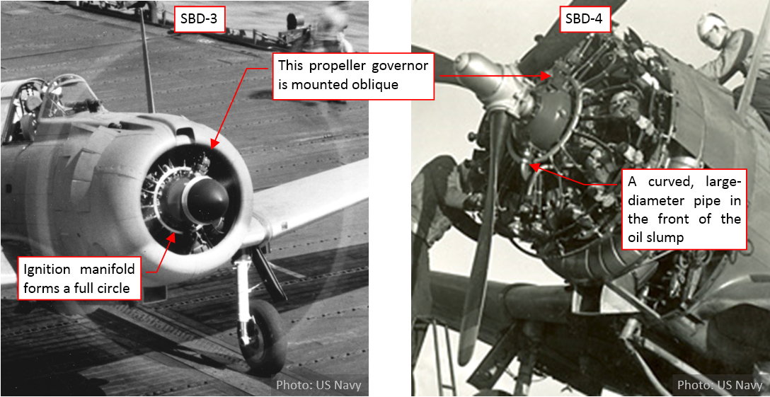
I quickly found another one: in the R-1820-52 the ignition manifold forms a full circle, while in the R-1820-60 it is a 300⁰, “U-shaped” arc). I decided to look closer at the differences between the R-1820-52 and -60. I will report my findings in the next post.
You can download the model presented in this post (as in second-last figure in this post) from this source *.blend file. It is available under CC-BY license and can be useful for other aircraft, for example the B-17 or the F4F-4.
2 Likes
I decided to write a post about the first decade of the R-1820 “Cyclone” development (up to the R-1820-60 version, i.e. 1940). This engine was used in many designs from 1930s, and you can find the references to its various models in many technical specifications. However, sometimes it is difficult to determine how such a referenced version looked like! The early models of the “Cyclone” were produced in small batches, so there is less historical photos. Sometimes even the specialists from the museums are misguided: in one of them, you can find a SBD-3 fitted with the engine and the propeller from the SBD-5. My query, which resulted in this article, started with comparison of the R-1820-60 (used in the SBD-5) and the R-1820-52 (used in the SBD-3 and -4). I have found so many differences, that I started to wonder about the engine used in the pre-war SBD-1 and SBD-2. (They used the earlier “Cyclone” version: R-1820-32). The results presented below may be interesting to the modelers who recreate aircraft from this period (for example – the Curtiss “Hawk” biplanes, or the Grumman F3F-2 “Flying Barrel”).
Let’s start from the beginning: below you can see the first model of the R-1820 family, designed in 1931:
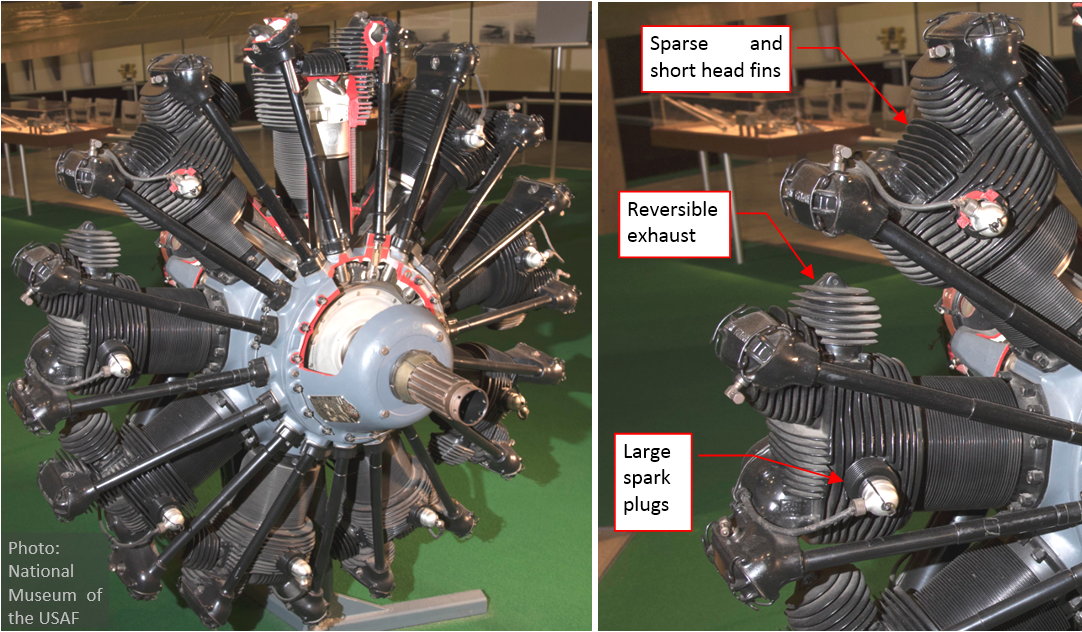
Frankly speaking, there is only a general resemblance to the later “Cyclone” versions. Note the small crankcase front section and the “archaic” cylinder heads. (They have different shape, and their fins are much shorter and widely spaced: these are indicators of a simpler casting technology). Another strange feature is the exhaust, which could be also mounted in the reversed (i.e. forward) direction. (Some of the aircraft from this era used front exhaust collectors). This engine used large spark plugs, mounted horizontally (in parallel to the centerline). It was rated at 575hp on takeoff, and used in some contemporary designs, like the Curtiss “Hawk” biplane.
Before introducing the next “Cyclone” version, let’s try to decode its symbol. It seems that there are two parallel conventions: one used by the engine vendor (Wright Aeronautical), and another used by the US Air Corps and the Navy.
Wright designated this engine as R-1820E. The “R” stands for “radial”, “1820” is the displacement (in cubic inch), and the “E” denotes the model. There were also other, 7-cylinder “Cyclones” produced by Wright during 1920s, as well as smaller 9-cylinder “Cyclone” (R-1750) produced before 1931. About 100 of these “Cyclones” were sold for the Navy flying boats. Technically, this “E” model, featuring 1820 in[SUP]3[/SUP], was an advancement.
For the US military purposes, there was a similar convention, in which this engine was referred as the R-1820-1. The “R” stands for “radial”, “1820” is the displacement (in cubic inch), and the “-1” is the sequential version number. (I suppose, that this “sequential” suffix applies to the purchasing chronology, not to the engine development).
Wright offered simultaneously two variants of the same engine: direct drive and geared. (“Direct drive” means that there was no reduction gear). The “geared” models had the “G” prefix: for example GR-1820E. According the “military” convention, each of these “parallel” versions could have a different sequential number (depending on the date of the first purchase?).
The next development stage was the R-1820F. It featured larger cylinder heads (because of the deeper and closer cooling fins), simple supercharger, forged (and then machined) main crankcase, and many other important improvements. It was difficult to find a decent photos of this model. Finally I identified one (military designation: R-1820-19) in National Museum of the USAF. It was mounted in the only preserved Martin B-10:
This particular airplane was built in 1938 for Argentina, as the export model Martin 139W. (In 1970 this only survived B-10 in the world was given to the US as a donation from the Government of Argentina. It was later restored by the National Museum of the United States Air Force). It seems that Martin used in this aircraft the R-1820-19 engines (rated at 665hp). It was the same “Cyclone” model as in the original US Army versions (YB-10 and B-10, delivered in 1934).
Looking for the decent photos of the “F” model, I finally found a few pictures of the Soviet M-25 engine. (In 1933 the Soviet Union bought a license for one of the R-1820F variants. First Soviet “Cyclones” were built in 1934 from kits delivered by Wright Aeronautical. After conversion to the metric system, from 1935 they were produced in thousands by a dedicated factory in Perm). Below you can see photos of this engine:
Wright licensed to the USSR the direct drive version named R-1820F3.
The direct drive versions of the “Cyclone” had much shorter crankcase front section than the geared models (compare the figure above and the B-10 picture). Their oil slump also lacked the “L”-shaped forward pipe. (I suppose that it was not needed in the much shorter crankcase, without the reduction gear inside). The deflectors, attached to the cylinder heads on the photo above, have circular shape. (They differ from the rectangular deflectors mounted in R-1820-19. I will come back to this issue in a moment, discussing the “G” model). It seems that they removed corresponding side deflectors from this museum exhibit. On the crankcase front section there is a small base for the governor of a variable-pitch propeller. The rocker covers differ from the “E” model, and Wright engineers added small attachment points at their ends. (These points were useful for mounting the large NACA cowlings). Note that most of the cooling fins concentrate around the exhaust valve. There are only few of them around the intake valve.
The “F” model of the “Cyclone” was a commercial success, powering many aircraft in the first half of the 1930s (for example – the Douglas DC-2 airliner). The later versions of this engine had two-digit numerical suffixes, like “F52” or “F62”. (It seems that these middle “5” or “6” indicate an improved version). They were rated at about 745 – 785hp. The GR-1820-F52 reached 890hp for takeoff, but it was the upper limit of this design. (The F52 model had the lowest blower ratio: 7:1, and it was rated at 725hp at sea level and 775hp at 5800 ft.
The next “Cyclone” model was the R-1820G. It had larger cylinder heads than the “F” version (as explained in this article, to get higher power from a cylinder, you need the larger area of its cooling fins). I have found some detailed pictures of an early, direct-drive “G” versions in the F3F-2s restored at Chino Planes of Fame. Comparing to the original photos, it seems that this is not the R-1820G5 (R-1820-22), but another “Cyclone” version. However, it seems to be nearly identical with the original engine:
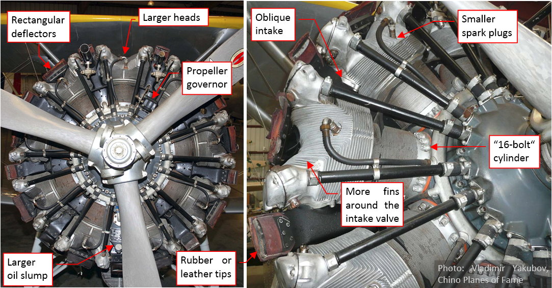
It is not clearly visible on these photos, but the intake duct in the heads is set at about 45⁰ to the centerline, as in the blueprints of my R-1820-60 version. (In the “E” and “F” models it was parallel to the centerline, as the exhaust duct). The intake valve is finally covered by short fins. The spark plugs are thinner, and placed in a less asymmetric way than in the “F” model (in fact, this head looks similar to the version that I recreated in the previous post). The top rocker covers received the new shape and four bolts around their rims. On the left photo you can see the attachment points on the rocker covers, introduced in the “F” version (they are more visible here than on the previous picture). The higher pressure produced in the combustion chambers of this engine increased the number of attaching bolts to 16 per cylinder (there were 12 in the “E” and “F” versions). On the left photo you can see the details of the “rectangular” deflectors. Note their elastic tips – I think that this brown material is the rubber (or leather?). The original R-1820-22 (GR-1820G5) engine, used in the F3F-2, was rated at 950hp for takeoff. (The same engine was used in the F2A-1 Buffalo, and the export version of this fighter, Brewster 239, delivered to Finland).
Figure below shows the later, geared version of the “Cyclone” (it was rated at 930hp at 2200 rpm for takeoff):
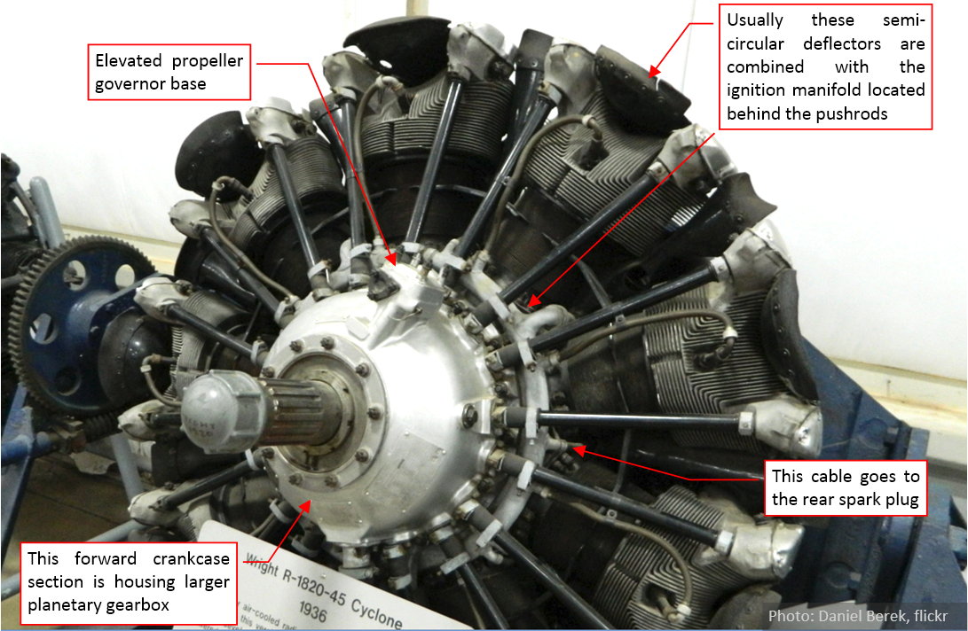
Note that its front crankcase section is larger than in the geared “F” model (compare it with the B-10 picture). Wright referred to these more powerful series as “Cyclone” GR-1820-G100. I studied many historical pictures of these “G” engines. It seems that in certain versions Wright placed the ignition harness in the front of the valve pushrods, while in the other versions - behind these pushrods. The semi-circular deflectors occur together with the latter variant of the ignition harness. In such a configuration every second cable goes between the cylinders to the rear spark plugs.
The “rectangular” deflectors usually occurs in the engines withe ignition harness placed in the front of the pushrods:
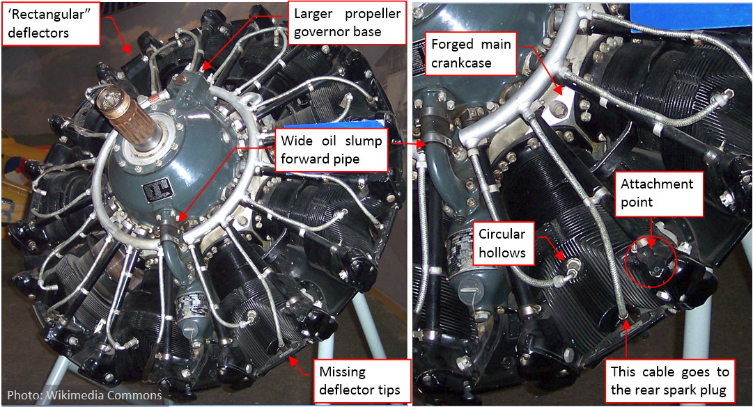
In such a configuration the cables go to the rear spark plug around the cylinder head (and across its deflector – as you can see in figure above). The picture above shows the later “Cyclone” G100 model, most probably one of the R-1820-5x series (I am not able to precisely determine this version). It is nearly identical with the R-1820-52 (used in the SBD-3 and -4). This photo also show us detailed fragment of the angular main crankcase section. (It was built from two symmetric, forged and machined aluminum parts). Similar crankcases appear in the “F” family. In this later model the base for the propeller governor was even more elevated than in the R-1820-45 (compare this photo with the previous illustration). I do not think that the engine from figure above uses a different version of the deflectors. I rather suppose that this particular museum exhibit uses their standard “rectangular” model with the flexible tips removed.
I have just a few pictures of the engines used in the earlier Dauntless versions (SBD-1 … -4). Below you can see two of them (unfortunately, both are in low resolution):
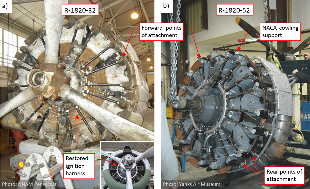
The engine depicted in figure “a”, above belongs to a restored SBD-1 (BuNo 1612). (When you can see the original wreck, you can be at least sure that this is the original piece). The engine in figure “b”, above, was attached to the SBD-4, restored in Chino. It seems that there are no external differences between these two engines (at least as viewed from the front). The “-32” is missing the ignition harness, but you can see in the attached miniature that the restored version of this harness is identical to the “-52” on the right. Both engines have the standard, “rectangular” deflectors with flexible tips. Note how Douglass engineers make use of these auxiliary attachment points on the valve covers (figure “b”, above). The cowling flaps bow was supported by the rear row of these points, while the supports of the NACA cowling use the forward attachments.
Both engines – R-1820-32 and R-1820-52 – were rated at 1000hp for takeoff. I have no information if there were any differences in their blower or gear ratio. The most powerful “Cyclones” G were rated at 1200hp for takeoff (the geared R-1820G5E).
The next “Cyclone” generation was a result of significant reengineering. Wright referred them as the GR-1820-G200 series (or, skipping the “G” suffix, as the R-1820-G200, because there were no direct drive versions in this family). It seems that the first of these models had military symbol R-1820-56. One of them is the R-1820-60 (the version that I already have recreated) and the R-1820-66 (version used in the SBD-6, presented in figure below):
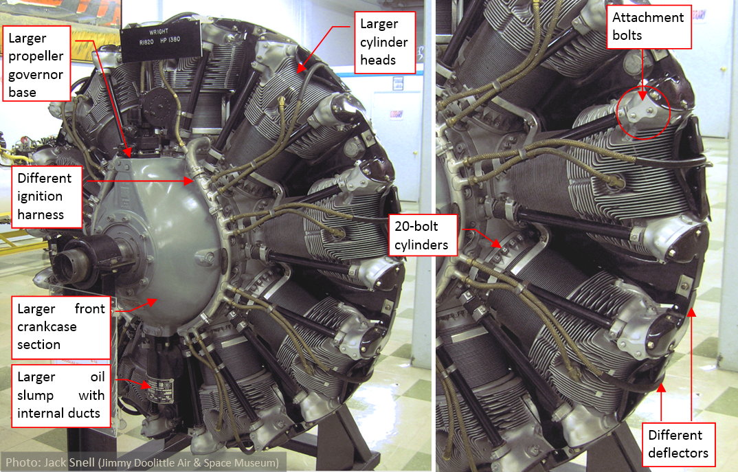
Frankly speaking, Wright has redesigned most of this engine, so it is easier to point out the elements that did not change between the G100 and G200 series: spark plugs and propeller governor (these two items were delivered by the third party vendors). While preserving the overall dimensions and mounting points, all of their external details are different. In the G200 the enlarged front section of the crankcase housed even bigger reduction gear and more efficient auxiliary shafts for the propeller governor. The pushrods became slightly shorter, thanks to the enlarged diameter of the front crankshaft. The cylinder heads grew bigger, because of the longer fins. (It was another increase of the cooling area - thus the shape of these heads is slightly different than in the G100 series). The deflectors are all-metal, without the flexible tips, and have different mounts among the cylinders. The cylinders are prepared for the high-octane fuel which means higher pressures, thus their bases feature 20 bolts (instead of 16 bolts in the G100 series). What is not visible on this photo, the main crankshaft section (under the cylinders) is a steel cast of gently curved shape.
In this engine you can see different auxiliary attachment points: double bolts on each intake rocker cover (the exhaust rocker covers have none). (This “bolted” mount already appeared in the late G100s models, but not in the engines used in the SBD-1 …-4).
The R-1820-60 was rated at 1200hp for takeoff. It was also used in the B-17C, D, E, and F. The R-1820-66 was rated ever higher: at 1350hp for takeoff. (Similar R-1820 version was used in the B-17G).
Finally, to increase the overall confusion (hopefully of the Axis spies ![]() ), at the beginning of 1940s Wright Aeronautical altered its naming convention. Since this time:
), at the beginning of 1940s Wright Aeronautical altered its naming convention. Since this time:
- The R-1820G and GR-1820G series are referred as “Cyclone” 9GA (shortcut: C9GA);
- The R-1820-G100 series are referred as “Cyclone” 9GB (shortcut: C9GB);
- The R-1820-G200 series are referred as “Cyclone” 9GC (shortcut: C9GC);
Thus you can find in various source documents and the books three different symbols for the same engine. For example – the full title of my Wright service manual from 1943 is: “Overhaul Manual/Wright Aircraft Engines Cyclone 9 GC”. This means that it applies to the R-1820-G200 series. In particular, this group includes the models named in the U.S. Army and Navy documents as the R-1820-60 and the R-1820-66.
Well, all in all this means that I have to recreate another engine: R-1820-52 (late G100 series) for my earlier Dauntless models: SBD-1, SBD-2, SBD-3 and SBD-4. There are too many differences to adapt the R-1820-60 model that I have already created. I describe shortly this “subproject” in the two next posts.
Bibliography:
- “Parts Catalog for Wright Cyclone Aircraft Engines Series GR-1820G-200”. Wright Aeronautical Corporation, 1940;
- “Wright Cyclone 9 Aircraft Engine, series C9-GC: Installation, Operation, and Service Maintenance”. Wright Aeronautical Corporation, 1942;
- “Overhaul Manual Wright Aircraft Engines Cyclone 9 GC”, Third Edition. Wright Aeronautical Corporation, 1943;
- “Operation and Service Manual: Wright Cyclone 9 Aircraft Engines Series C9GA, C9GB, C9GC”, First Edition. Wright Aeronautical Corporation, 1943;
- Francis H. Dean “America’s Hundred Thousand: The US Production Fighter Aircraft of World War II”, Schiffer Publishing, 1997 (ISBN: 0-7643-0072-5);
- Francis H. Dean, Dan Hagedron “Curtiss Fighter Aircraft – a Photographic History 1917-1948”, Schiffer Publishing, 2007 (ISBN: 978-0-7643-2580-9);
- Wawrzyniec Markowski “Boeing B-17 Flying Fortress”, parts 1 and 2, AJ-Press 2004, (ISBNs: 83-7237-143-1 and 83-7237-152-0);
- Barret Tillman “The Dauntless Dive Bomber of World War Two”, Naval Institute Press, 2006 (ISBN: 1-59114-867-7);
- Bert Kinzey “SBD Dauntless”, Detail & Scale, 2016 (ISBN: 978-0-9860677-5-4)
- Robert Pęczkowski “Douglas SBD Dauntless”, Stratus, 2007, (ISBN: 978-8389450-39-5);
- Kimble D. McCutcheon “Wright R-1820 ‘Cyclone’”. Aircraft Engine Historical Society, www.enginehistory.org, 1999, revised: 2014;
- Поршневой авиационный двигатель М-25 (Wright «Cyclone» R-1820 F3) (in Russian). Accessed 2018-07-10;
- The Wright R-1820 “Cyclone” Engine. Acessed 2018-07-02;
- Martin B-10. Accessed 2018-07-12;
Photo collections of:
- National Museum of the USAF, Riverside;
- Muzey V. P. Chkalova (Музей В.П.Чкалова), Chkalovsk;
- Planes of Fame, Chino;
- National Naval Aviation Museum, Pensacola;
- Yanks Air Museum, Chino;
- Jimmy Doolittle Air & Space Museum, Travis AFB;
- “Life” magazine
1 Like
nice touch for doc and summary
only thing missing is the life expectancy for these engines !
I read some where that for the B-17 first engines in UK WWII
they lasted only 25 hours !
thanks
happy bl