SBD Dauntless (US Navy dive bomber)

Well, I focused on the visual differences between subsequent versions.

BTW: As I remember, the first few B-17s in UK were 20 B-17C, delivered to RAF in March 1941. They tried to use them as “stratospheric bombers” - a few of them bombed Wilhelmshaven from 30 000ft, then Brest. The effects of these attacks were close to nil. They operated much higher than the B-17s used by USAAF in the 1943 and 1944, and these early B-17C version caused many mechanical troubles. On of their basic reason were the extremely harsh conditions during the long flight on a very high altitude - this experience was later applied to the B-17E and F.

Following the conclusion from my previous post, I have to recreate yet another “Cyclone” version: the R-1820-52, used in the SBD-3 and SBD-4. Fortunately, the R-1820-32, used in the SBD-1 and SBD-2, seems to be identical (at least – as viewed from the front), thus I do not need to recreate this “Cyclone” variant. I will describe the modeling process of the R-1820-52 in the “fast forward” mode, compressing the whole thing to two posts: this and the next one.

Initially I identified just two differences: the shape of the front crankcase section and the different ignition harness. I assumed that I will be able to reuse most of the R-1820-60 components. I had discovered most of the issues described in my previous post while working on this R-1820-52 version. In fact, it occurs that such an attempt to create a 3D model of such an engine is like an scientific experiment: it verifies the initial hypothesis and reveals the new facts that otherwise would be overlooked.

I started by renaming in the source Blender file the scene that contains the previously finished engine as “R-1820-60” (the “military” symbol of an engine belonging to the “Cyclone” G200 family). Then I created a new scene, named “R-1820-52” (the G100 family). This is my new “working place”. I copied there (precisely speaking: “linked”) some of the “R-1820-60” parts that were common for the G100 and G200 family. In this “*-52” version I followed the same “building path” which I used for the previous one. So I began with the crankcase and the basic cylinder elements:

I assumed that all the key dimensions and bases are identical in both versions, just the details are different. This assumption allowed me to determine the shape of the forged, “angular” main section of the G100 engine crankcase using just a few photos of its fragment (as in Figure “a”, above). (This element is quite obscured on all the photos that I had). The nine side faces of this section had to fit the corresponding cylinder bases. The adjacent, oblique faces between the cylinders had to fit the space between cylinder bases and the front / rear plane of this central crankcase section. However, while fitting the crankcase and the cylinders, I also had found that the 16-bolt cylinder base used in the R-1820-52 had a longer straight side segment (Figure “b”, above) than the 20-bolt base used in the R-1820-60. Because most of the cylinder parts were assigned to the E.100.Cylinder Base object (the “bare” cylinder), I decided to split it into the upper and lower part. The mesh of the upper part is assigned to this original E.100.Cylinder Base object, and used in both engine versions (Blender scenes). Each of these engines has its own lower part of the cylinder (marked in red in Figure “b”, above). The 20-bolt version is used in the “R-1820-60” scene and named G.100.Cylinder Base, while the 16-bolt version is used in the R-1820-52 scene and named F.100.Cylinder Base.

The crankcase front section in the R-1820-52 had smaller diameter than in the R-1820-60, and different side silhouette. Thus I had to model this fragment anew. I split it into 9 identical segments, as I did in the R-1820-60. However, after some measurements, I decided that the disc that closes this crankcase from the front is identical in both versions (Figure “b”, above). To avoid eventual “orphaned” objects in my further work, I used this disc the root object in the “parent-child” hierarchy of both models.

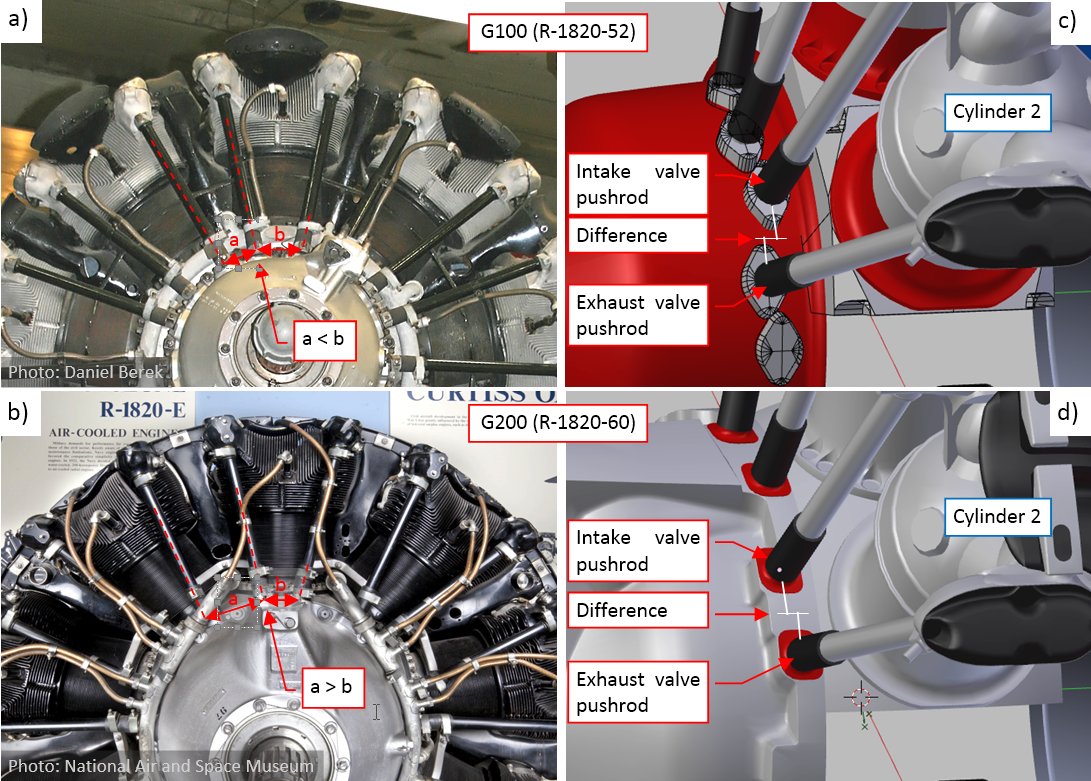
In Figure “b”, above you can also see the initial versions of the pushrod bases, which I placed around the front crankcase section. They had characteristic “diamond” shapes. I recreated the “pattern” of these pushrod bases around the crankcase. This work led me to another small discovery: the G100s and the earlier “Cyclone” versions used different valve pushrod arrangement than in the G200s:

Compare the a and b distances in Figures “a” and “b”, above. As you can see, there is wider space between the intake and exhaust valve pushrod (the b distance) in the earlier “Cyclone” G100 series (incudes the R-1820-52) than in the later G200 (includes the R-1820-60) series. The reverse proportion occurs between the pushrods of the adjacent cylinders (the a distance in Figure above). It seems that the pushrods in these earlier “Cyclones” were set along the radial directions, while in the later (G200) models they were set at a different angle.

There is also another difference: Wright engineers reversed in the G200s the order of the pushrod cams. In the G100s and earlier engines the base of the intake valve pushrod was shifted forward (Figure “c”, above). In the G200s they set the exhaust valve pushrod first (Figure “d”, above).

To match the rear rim of the front crankcase with the photos, I prepared its simplified, “block” version (Figure “a”, below):

This “block” version is built of several simple elements, like the pushrod bases, the rear, flat elements, and so on. Once their shape matched the reference pictures, I joined these elements into the single, more complex object using temporary Boolean (Union) modifiers. Finally I joined it with the basic front crankcase segment (Figure “b”, above). I also rounded the new intersection edges with a multi-segment Bevel (Weight) modifier.

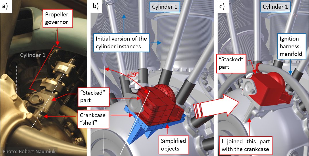
In the G100s (incl. R-1820-52) and earlier “Cyclone” models the propeller governor was mounted at an oblique angle on a quite complex “shelf” extending from the crankcase:

I applied here the same “approximation first” method, using intermediate simplified parts (Figure “b”, above). (As you probably observed, it became my usual approach to such complexities like this one). After the “fitting” phase I joined the bottom part of this “shelf” with the crankcase, and rounded the resulting edges (Figure “c”, above). On top of the “shelf” there was an additional, “stacked” part (I think that it was a kind of a cover). In the pictures above I marked it in red. In the final version I left it as a separate part, attached to the crankcase by the “parent” relation.

In the background of figure above you can also see the first versions of the cylinder instances (I will modify them in the next steps), and the ignition harness manifold. (I preferred to fit it on this early stage of this the model, to avoid unwanted surprises later).

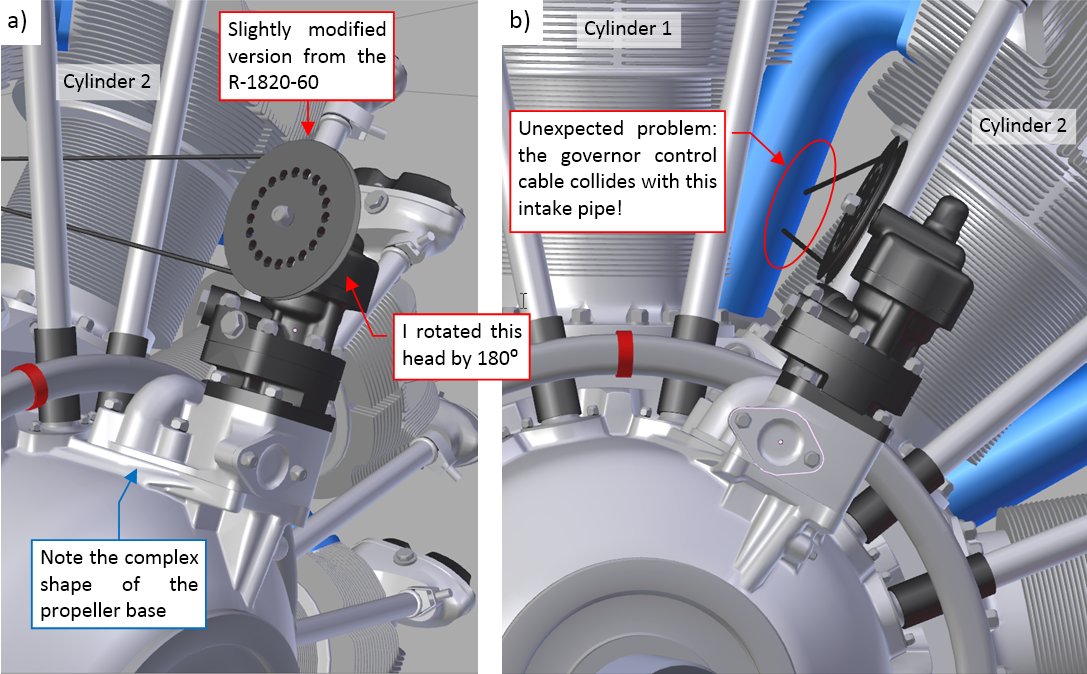
When the “shelf” was ready, I put the propeller governor in place:

I copied this governor from the R-1820-60 scene, then modified it a little (rotating the head with actuator wheel by 180⁰). Unlike in the R-1820-60, this object is set in the position parallel to the engine centerline. Looking from the front, it is mounted in an oblique position just to pass the control cable in the gap between Cylinder 1 and Cylinder 2. However, looking along this cable, I stumbled upon a new problem: it collided with the intake pipe! (Figure “b”, above).

I quickly found a photo that explained me this puzzle (Figure “a”, below):

As you can see in the picture above, the intake pipes in the G100s models formed large arcs, leaving the gap between the Cylinder 1 and Cylinder 2 open for the control cable. This means that I have to modify these pipes in my R-1820-52 model.

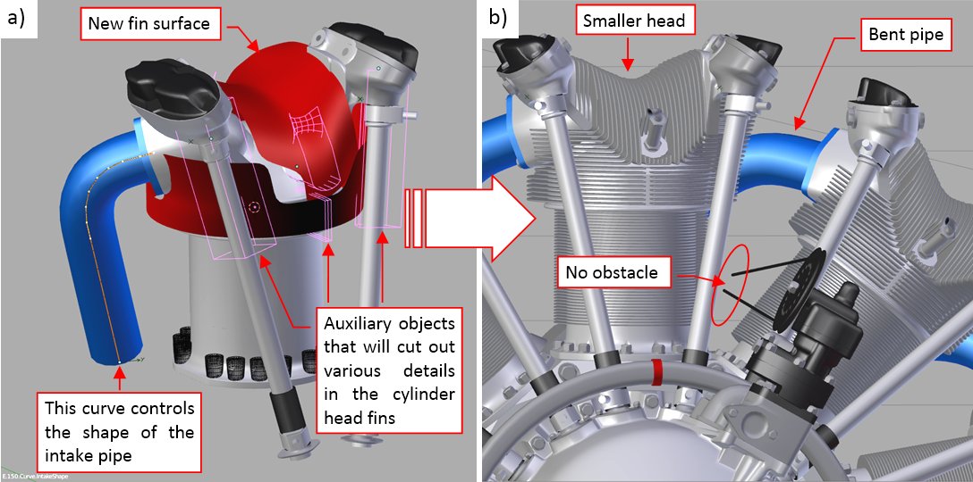
Thinking about the altered angle of the valve pushrods (see the second figure in this post) I checked the clearance between them and the cylinder head. In the R-1820-60 they were placed in deep troughs, “cut out” in the cylinder fins. I was surprised by the photos showing that in the R-1820-52 these pushrods would not collide with the cylinder head, even if this head did not have the minimal, shallow troughs. I studied this cylinder head closer: the spark plug hollows also seemed to be shallower, and the upper contour of the fins (as viewed from the front) was lower in its middle section. I started to compare proportions of these cylinders. Finally I decided that the fins in the heads of the R-1820G and R-1820G100 series were shorter than in the R-1820G200 (i.e. in my R-1820-60). I estimated that the G100s cylinder heads had 10% smaller diameter than the G200s heads. (It means that cooling area of the G200 cylinders was about 30% larger than the cylinders used in the G100s. It matches the differences in their power).

Well, now I had to apply these findings to my model:

Fortunately, the “pattern” of the cylinder fins seems to be nearly identical in the G200s and G100s cylinder heads. (I have found just a single minor difference in their forward part). Thus all what I had to do was to prepare new, smaller “fin boundary surface” (Figure “a”, above), then apply it using Boolean (Intersection) modifier to the same mesh of the fin planes. I could reshape the intake pipe by altering the shape of its control curve (used in the Deform Curve modifier of the intake pipe). You can see the results in Figure “b”, above)

Figure below shows the actual state of the R-1820-52 model:

Cylinders 2-9 are instances of the object group named F.G05.Cylinder. The source of this group are the components of the Cylinder 1. When I modify the source Cylinder 1, Blender immediately updates the remaining eight cylinders. Components of Cylinder 1 lie on two layers: 3 and 13, while the group instances belong to the single layer: 3. I have found such an arrangement most useful for the constant work on the cylinder details – I often did it on layer 13. Note that I also modified the bases of the intake pipes (I had a single, poor quality photo of this area). In general, it seems that the rear crankcase section of the G200s that I roughly recreated in the R-1820-60 is similar in the R-1820-52. The same applies to the magnetos and oil pump.

This engine still lacks the cylinder deflectors, oil slump, and spark plug cables. In the next post I will finish all these details and fit it into the NACA cowling.

You can download the model presented in this post (as in figure above) from this source *.blend file.

2 Likes

is there a post showing all the different file models ?
but also what license is it ?
at least give your name for modeller !

in last post there is the file for the R-1820
but I think there is also another file for the other model

file seem to be very small for such a complex model

are these models going to be ported to 2.8 ?

thanks
happy cl

There is no “table of contents” of the published files.
At the end of each post you can find the model (the link to the *.blend file). It contains the model in the state as described in this particular post. In some cases, when I discussed the textures, I also provided links to the GIMP/Inkscape source files.

This work is licensed under
Creative Commons Attribution 4.0
International License

By: Witold Jaworski (airplanes3d.net)

Frankly speaking, I did not want to patch all this law stuff into these intermediate stages of the model. (For example: I think that such a statement would look strange in a file that contains the wing alone).
I placed this statement in the file that contains the finished R-1820-60 (see the model linked at the end of this post)

As I explained, you have to scroll the posts, to find the particular file you are looking for. For example, In this post you can find the latest state of my SBD Dauntless model.
Because of the engine complexity I decided to make it in a separate Blender file, then append to the main model.

Because I used the group instances to recreate its cylinders and deflectors (examine the model enclosed to this post). Also note the relatively low number of vertices and faces.

All the intermediate models that I have published so far, will remain in the current state (saved in Blender 2.7) - actually I see no reason to convert them.
Eventually in the future, when Blender 2.8 reaches the productive version, I will switch to it, so the later models will be saved in this new version. However, at this moment nobody knows when it happens.

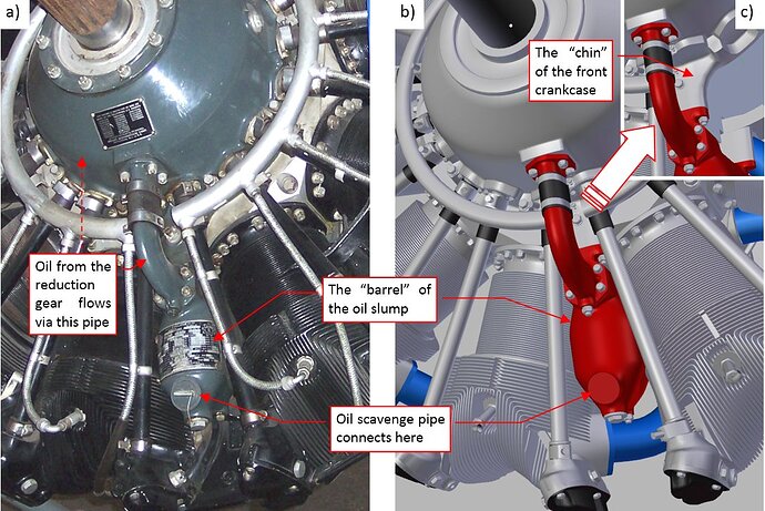
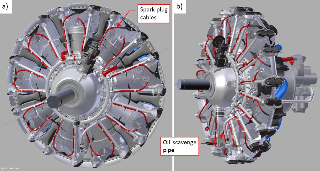
In this post I will finish my model of the R-1820-52 “Cyclone”. (This is the continuation of the subproject that I started reporting in the previous post). Figure below shows the oil sump, used in this engine:

Oil sump shape vary even within the same G100 family: I observed different proportions of the front “barrel” and its forward pipe in the early and the later of these “Cyclone” models. This particular oil sump (Figure “a”, above) was used in the later G100s engines, like the R-1820-52. Apart from the forward pipe, it was also attached to the front crankcase via a “chin” (Figure “c”, above).

While I have a few photos of the forward part of the oil sump, I have not any evidence of the shape of its rear part. (Because of the different shape of the intake pipes, I do not think that it forms the “Y-shaped” fork, like in the G200 series). All what I had found is a single, poor quality photo of the damaged engine recovered from Lake Michigan (Figure “a”, below):

There is “something” at the bottom of this crankcase: it has a trapezoidal shape and (probably) two inner (oil?) ducts inside. I decided that this is the rear base of the oil sump (Figure “b”, above). It is quite thin (no more than 1 in), fitted between the crankcase main section (cylinder bases) and the intake pipe (Figure “c”, above).

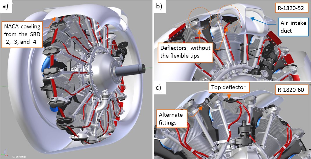
As I described in the post about “Cyclone” versions, the R-1820G100 and R-1820G series used the same deflectors. Thus I recreated the upper deflector (the “rectangular” version) using photos of a restored R-1820G engine, from the F3F-2:

I recreated the sheet metal frame and the flexible (rubber?) tip (Figure “a”, “c”, above). The photos from the recovered SBD-1 show, that there were some variations in the shape of the deflector rear part, around the spark plug. In the R-1820-32 from the SBD-1 I can see a kind of additional cut-out for the ignition cable, which is missing in this F3F-2. (F3F-2 had a different ignition harness – compare the deflectors in Figure “b” and “d”, above).

The top cylinder in the SBD-2…-4 had the elastic tip removed. (Because of the fitting the engine to the “Duntless” NACA cowling – I will show it later n this post). Thus I defined this deflector as another group instance, named F.G11.Deflector. (In the R-1820-60 model the top deflector is the part of the cylinder group).

In similar way I modeled the side deflector:

This deflector also has a flexible tip. As you can see, I skipped here some details (Figure “a”, above) that do not appear on every object instance. Note the characteristic “bat-like” fitting in the front of this deflector (Figure “b”, above). (The R-1820-60 deflectors had different fittings).

The last remaining details are the spark plug harness and the oil scavenge pipe:

As in the previous case, I am leaving the invisible, rear part of this engine in the simplified, “block” form.

Finally, I imported the NACA cowling from the main model and placed the engine inside. Fortunately, it fits very well:

In the R-1820-52 (and -32 in the SBD-2) the deflector on the cylinder 1 top was mounted without the flexible tip, to fit below the air intake duct of the upper cowling (Figure “b”, above). Both of the cylinder 1 side deflectors also had their flexible tips removed, to fit below the gun troughs.

In the R-1820-60 and -66 (used in the SBD-5 and 6) the cylinder 1 featured the full top deflector. (It was possible, because, as I explained in this post, SBD-5 and -6 had two filtered air intakes, used for takeoffs. For the higher airspeeds there was enough “fresh” air for the air intake hidden behind the cylinder row). The R-1820-60 had different fittings on the cylinder 1 side deflectors that fit the gun troughs (Figure “c”, above).

The R-1820-52 is now complete, for the assumed level of details. You can download the model presented in this post from this source *.blend file. I think that it can be also useful for the models of the other aircraft that featured the geared R-1820G or R-1820G100 engines. (Like Brewster “Buffalo”, DC-2 and some versions of the DC-3, or Curtiss “Hawk” 75). The exhaust stacks are not included, because this is an aircraft-specific detail (as the eventual air intake filters in the SBD-5 and SBD-6). I will recreate these details in the next post, for both of my ‘Cyclone” models.

2 Likes

In my previous post I have finished the second variant of the R-1820-52 “Cyclone” engine, which was used in the SBD-3 and -4. (It looks like the earlier R-1820-32 model, mounted in the SBD-1 and -2). In the resulting Blender file linked at the end of that post you will find two “Cyclone” versions: the R-1820-52 (for the earlier SBD versions, up to SBD-4) and the R-1820-60 (for the SBD-5 and -6). Each of these engines has its own “scene”.

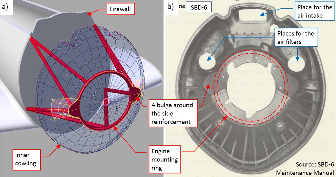
To “mount” these engines into my SBD models, I imported both scenes to the main Blender file. I defined each engine variant as a group, to facilitate placing them in the aircraft models as the group instances. I also added the firewall bulkhead and updated the shape of the cowling behind the cylinder row. (I will refer to this piece as the “inner cowling”). So far I did not especially care for the shape of its central part, hidden below the NACA ring. Now I updated it for the real size and shape of the engine mounting ring (as in figure “a”, below):

On the photos I noticed a kind of bulges, extruding from the both sides of the inner cowling (figure “b”, above). I assumed that they are shaped around small triangle plates welded on the sides of the mounting ring. (I have no photo to proof this assumption). Anyway, I modified the shape of the inner cowling in the SBD-5 to match this feature. I assumed that the inner cowling in the earlier SBD versions (SBD-4, SBD-3,…) also had such “bulges”.

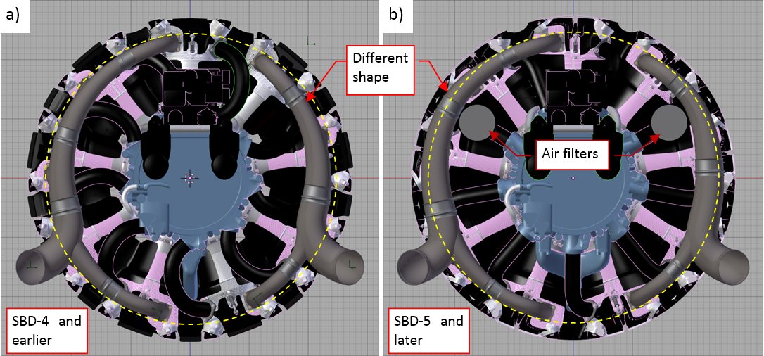
In Figure “b”, above, you can see three openings for the intake air in the SBD-5 and SBD-6: a rectangular one in the middle and two round holes on the sides. These side openings are for the air filters, intended mainly for the takeoff and landing:

The idea is that the during the dusty conditions on the airfield the direct intake door (1) is closed, while the doors for the filtered air: (2) and (3) are open. When the aircraft climbs higher, its pilot flips positions of these doors, closing the filtered air input (2), (3) and opening the direct input (1).

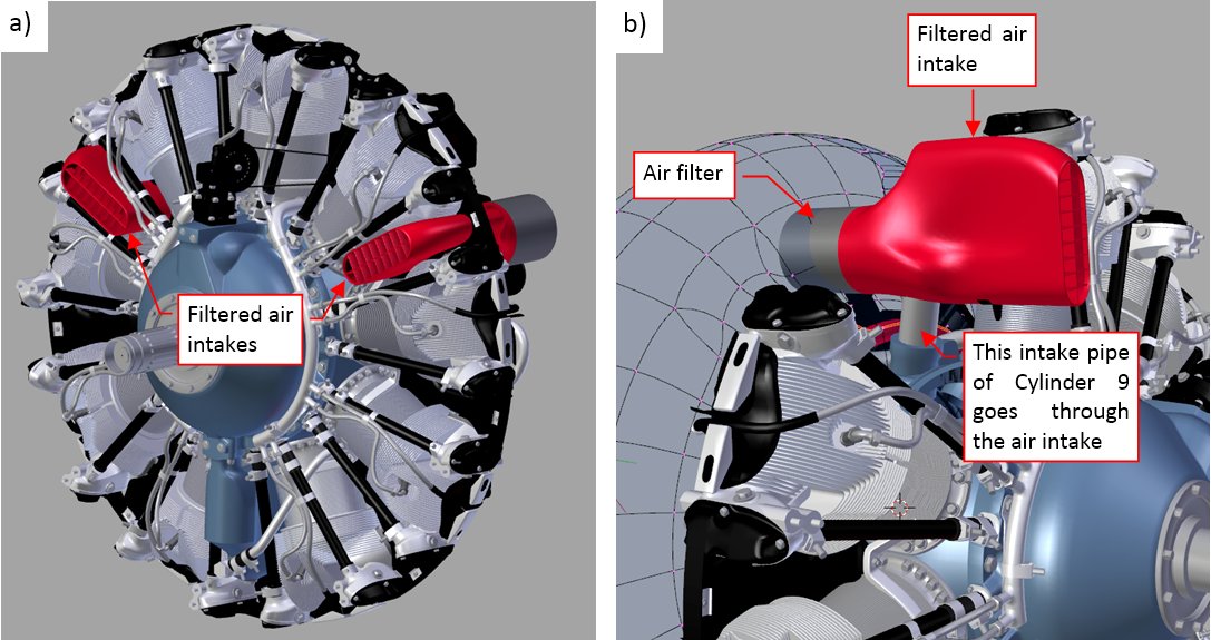
I added these two filters and their intakes to the R-1820-60 engine:

As you can see, these intakes are tightly fitted between cylinders 2-3 and 8-9 (Figure “a”, above), so they have a quite complex shape (Figure “b”, above). I do not have a photo for such an obscure detail, but the location of the filter determines, that the mixture intake pipes of Cylinder 3 and Cylinder 9 went through the corresponding intake body. (In principle, it is technically possible). I did not make holes in the deflectors between cylinders 2-3 and 8-9. (They would not be visible anyway, because both elements: the deflector and the intake are covered with black enamel).

The next aircraft-specific element is the exhaust collector. In the SBD-4 and earlier versions its outer contour had a circular shape (Figure “a”, below). However, in the SBD-5 (and -6) it went around the air filters, so it had a slightly different shape around this area (Figure “b”, below):

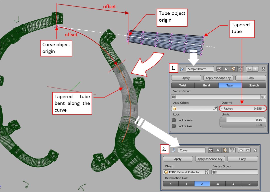
I built these collectors from simple tubular segments. Each of these segments is first tapered by the Simple Deform modifier (1), then bent along its shaping curve by the Curve modifier (2):

The offset of the original tube object from the curve object determines the origin of the resulting shape on the curve. Small gaps between subsequent tubular segments are hidden under the joining rings (as in the real collector). 95% of this collector is closed inside the NACA ring, so I decided to not recreate the fillets along the edges of the individual outlet pipes. (Joining all these tubular meshes would be a time-consuming task).

I used some photos to compare proportions of the exhaust collector, circular reinforcement and the cross section behind the NACA cowling in the SBD-3. The findings led me to the conclusion that I should modify the bottom part of the engine cowling:

Many months ago I found that the cross-section of the lower inner cowling in the SBD-5/SBD-6 had a non-elliptic shape (shown in Figure “b”, below). I also assumed, that such a cross-section also occurs in the earlier SBD versions. Now I can see that I was wrong: the photo above shows that in the SBD-1… SBD-4 it was a regular ellipse (as in Figure “a”, below):

It seems now that Douglas designers modified a little the bottom part of the engine cowling in the SBD-5, shaping its circular “chin” (Figure “b”, above). Maybe they did it because of the larger oil cooler used in this version? (It was required by the more powerful engine). If in the SBD-5 they shifted whole engine 3.5” forward, such an additional modification is also possible. (There was no any bulkhead at this station, and this cowling piece was already shaped anew).

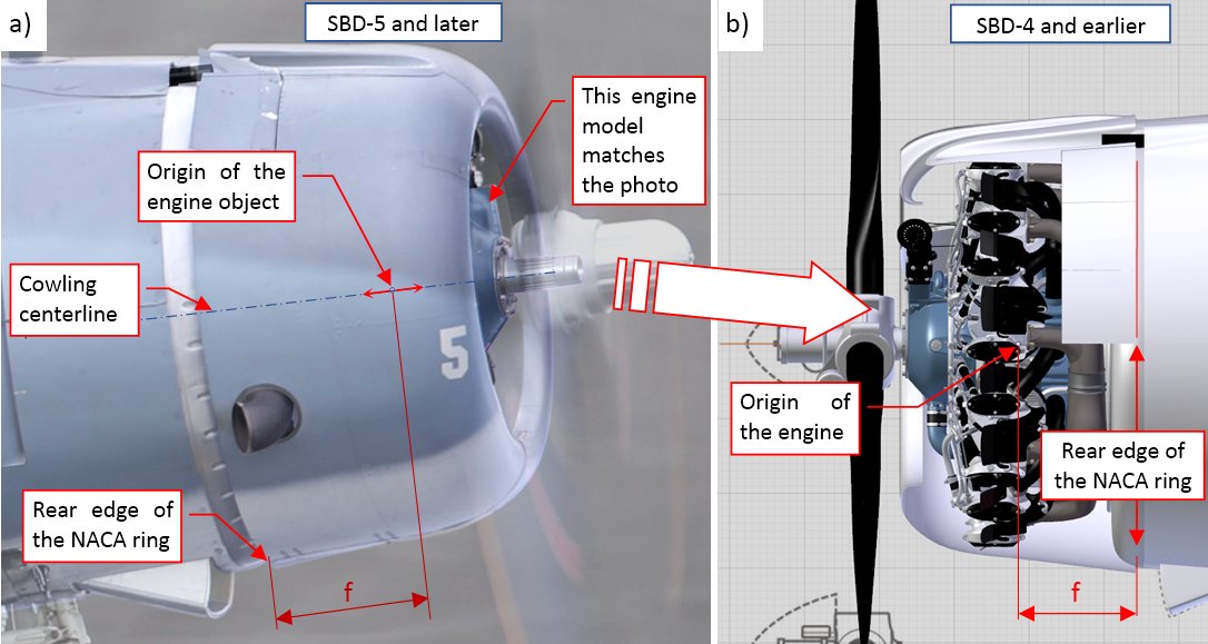
To determine the exact location of the engine along the fuselage centerline, I used the high-resolution reference photo of the SBD-5 (Figure “a”, below):

I shifted the engine along the fuselage centerline, until its crankcase matched the crankcase visible on the photo. Then I measured the f distance (Figure “a”, abve) and applied it to the SBD-3 and SBD-1 models. (In the SBD-5 the engine together with the NACA cowling was shifted forward, thus in the SBD-1 and SBD-3 I could not simply apply the absolute location of the engine origin).

Finally, I applied the materials to the engine models, copied the environments from the SBDs to the R-1820-52 and R-1820-60 scenes, and made test renders:

On these renders I placed the engines “in the middle of the air” just to be able to evaluate all their materials in the full light conditions. Due to relatively small size of most of the engine elements, I used here only the procedural textures. I did not apply to this engine models any oils stains or other dirt. The historical photos show that the blue enamel on the crankcase was kept surprisingly clear, even in the worn-out aircraft. The other parts of the engine are obscured under the NACA cowling, so there is no need for additional “dirt” textures. You can see it in the test render of the R-1820-60 “Cyclone” inside the SBD-5 NACA cowling:

You can download the model presented in this post from this source *.blend file.

In the next two posts I will work on the details of the cowling behind the cylinder row.

3 Likes

I am deeply in awe of your work. Thank you for the ongoing explanations.

1 Like

Amazing work. Keep it coming!

thorst, Mark06GT - thank you for following!


This time just about some minor details:

After “mounting” the R-1820 engines into my SBD models, I decided to recreate some details of the inner cowling (the cowling panels placed behind the cylinder row). In this post I will form the missing parts of the carburetor air ducts, hidden under the NACA ring. There are significant differences in this area between various SBD versions, which never appeared in any scale plans, or in any popular monograph of this aircraft. I think that the pictures presented below highlight these differences. They can be useful for all those scale modelers who are going to build the SBD “Dauntless” models with the engine cowlings opened.

Let’s start with the SBD-5s (and -6s), which are better documented (because they were produced in much larger quantities). They had a dual intake system, of the filtered/non-filtered air, which I discussed it in the previous post. I already recreated the two intakes of the filtered air, placed between the engine cylinders. Now I have to create the central, direct air duct and its opening at the top of the internal cowling.

Figure below shows the initial state of my SBD-5 model:

As you can see in Figure “b” and “c” above, initially the carburetor protruded from the simplified shape of the internal cowling. On this stage of work I was sure that the engine is at the proper location (I matched it against the reference photo in the previous post). Thus, I concluded that the shape of the internal cowling requires an update. To determine its real form, I reviewed the available photos. Unfortunately, I have only few pictures of this obscured area:

Figure “a” above shows an archival photo, taken at the Douglas factory. I can see there that edges of the cowling around the central air intake are shifted forward. Unfortunately, the closing, top element of this cowling is not attached here. I can see it in Figure “b”, above, taken from the front (which makes it less usable). On this picture I noted that the edges of the air intake are elevated above the cowling (by less than inch). It was confirmed by the pictures of the restored SBD-5 from the Pacific Aviation Museum Pearl Harbor (Figure “c”, “d”, below):

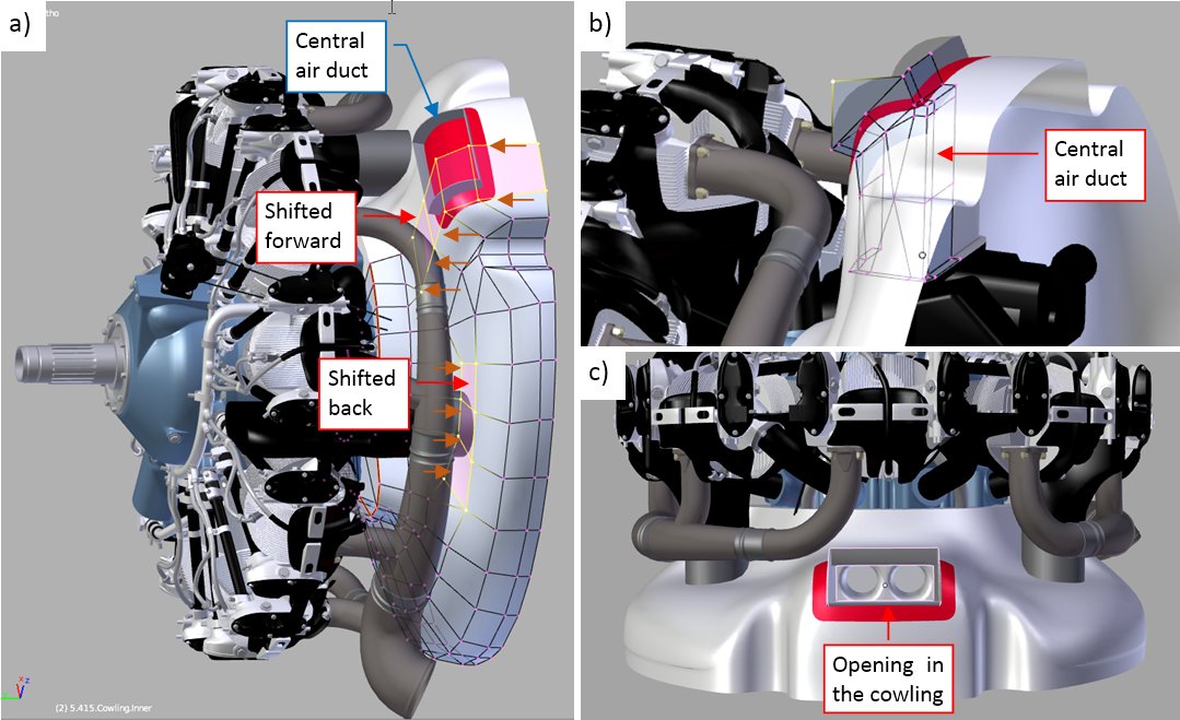
In Figure “c” above you can see the side contour of the inner cowling. I can see that the central area is shifted forward (marked in blue in Figure “b”, above), and side segments around air filters are shifted back (marked in brown in Figure “b”, above).

Figure “a” below shows these faces on the updated mesh of the inner cowling:

You can also see there the top of the air duct (this is a separate object). Figure “b”, above, shows its simple, “box-like” mesh. When both elements were in place, I used a Boolean modifier to cut out the central opening in the cowling (Figure “c”, above).

Let’s look at the corresponding area in the earlier SBD versions. Figure below shows the rear side of the SBD-3 engine cowling:

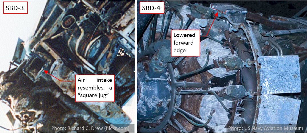
This case is quite different. It seems that the upper part of the inner cowling in the SBD-3 forms a “box” around the carburetor air duct. It was quite difficult to find any photo of this area taken from above (you know, in 99% cases the photographer stays below, on the ground). All what I have are the photos of the SBD-3 wreck, salvaged from Lake Michigan:

I learned from them that this “niche” had flanges around its edges, and the air duct stood inside it like a “statue”. (There was a lot of space around this duct). The designers even formed a kind of “pedestal” at the base of this “niche” (I marked it on the right photo).

Using all this information, I reproduced this “box”/“niche” in my SBD-3 model:

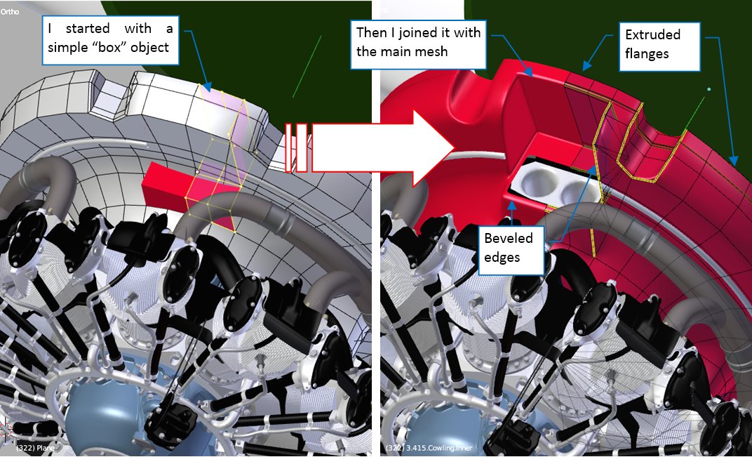
I started with a simple box, then I fitted it into the elliptical contour of the inner cowling. Finally I joined these two meshes, and rounded their edges using the Bevel (Weight) modifier. I also extruded the flange around its rear edge.

I also tried to determine the shape of the air duct. In this case the only available references were the photos of the SBD wrecks:

It seems that this part of the air duct had a “jug-like” shape. Its upper edges fitted the horizontal air duct mounted in the NACA cowling. (That’s why the forward edge of this intake is lowered a little – just as the bottom of the air duct in the NACA ring).

Figure below shows my attempt to recreate this part in the SBD-3 model:

I had some doubts about the forward edge of the upper cowling that overlaps the flange behind the air intake. Finally, I wrapped it around the topmost edge of the “niche” (see Figure “b”, above). I also improved the shape of the “pedestal” in the inner cowling. (It covers the front section of the carburetor – see Figure “a”, above). I assumed that the air intake looked like that in the SBD-2, -3 and -4, because they share the same air duct design.

I have not any reference materials about the internal air duct in the SBD-1. I assumed identical shape of the inner cowling as in the SBD-2, -3, and -4. Figure below shows other assumptions:

I assumed that the general shape of the internal, vertical air duct segment was as in the later versions. The only difference are the simpler upper edges, fitting the opening in the NACA cowling. (There was no “lower” part of the external air duct under the NACA cowling, which you can see in the SBD-2, -3 and -4).

In the next post I will add the last details to the inner cowling, finishing my work on the engine compartment.

You can download the model presented in this post from this source *.blend file. To reduce its size, it is stripped from the texture images. (During the last year the size of this source file has significantly increased, reaching 40 MB in the compressed form. More than 35MB of this amount is used by the texture images. Thus, I will preserve the texture images in the source file only when they are relevant to the topic of the post)

2 Likes

and here I thought I was nuts for modeling treenails on my boat…:joy: hats off, mate! this is insane modeling!!

are you going to make a high res model for the carburator ?

i’m trying to make one for the UK Hercule engine and have not been able to find good doc blueprints
only have like 15 photos
so very difficult to eye ball model in 3D

happy bl

heraSK: thank you, but your boat is awesome! (Did you try to use the group instances for the complex, repeatable elements? They make the work easier, and also improve the rendering times);

RickyBlender: Definitely, there is always some “eyeballing” (the blueprints, if present, are usually lacking at least some details). At this moment I am not going to recreate the carburetor details. (It would require a lot of time, while fortunately this part is hidden beneath the cowling);

This winter I am busy with my daily business project, so you will see the further progress in this model in the spring 2019. However, I have just found a little unpublished tutorial that I made in November, so I decided to publish during this break:


This post is dedicated to a minor feature, which I have found surprisingly demanding: modeling the grooves pressed in the curved surfaces of the aircraft panels. In the SBD you can see some of such reinforcements on the inner cowling, behind the cylinder row:

They are 0.7-1.0” wide (Figure “a”, above) and span over the inner cowling along its radial directions (Figure “b”, “c”, above). In the SBD-5 and -6 these reinforcing grooves occur only on the lower part of the cowling (Figure “b”, above), while in the earlier versions (SBD-1, -2, -3, and -4) they are also present on the upper part (Figure “c”, above).

Even when the flaps on the NACA cowling are closed, you can still see rounded endings of these grooves around the cowling rear edge:

In the earlier versions (SBD-1…SBD-4) they appear on the narrow strip behind the NACA cowling (Figure “a”, above). You can see more of the upper grooves when the NACA cowling flaps are set wide open. In the SBD-5 and -6 the engine and the NACA cowling were shifted forward by 3.5”, and the gap between the NACA ring and the inner cowling is wider. Thus, in these versions you can see even longer fragments of the grooves behind the NACA cowling (Figure “b”, above).

Such grooves appear on many sheet metal elements, so I decided to write this post as a small tutorial that teaches how to recreate these elements. Thus, do not be surprised when I list the detailed Blender commands in the text below.

Usually I would recreate such a feature using bump map. However, this is a special case: it may happen that in the future I will also recreate most of the inner details inside this NACA cowling (for a cutaway picture). This means that in the future I will have to render some close pictures of this area. That’s why I decided to model these groves in the mesh geometry. (It seemed that this addition did not require any substantial retopology, due to the radial direction of these groves. Their layout matched the general “spider web” mesh layout of this inner cowling).

There are two methods to reshape the mesh in Blender:

  • Classic, manual modification of the faces, edges and vertices;
  • Displace modifier, which uses a texture image (a kind of bump map) to shift (displace) the mesh faces along their normal directions;

The Displace modifier is a great tool for the cloth wrinkles and similar effects. However, for the relatively sharp edges as in these grooves, it would require an extremely dense mesh (subdivided 4 or 5 times). Because the Displace modifier required significant increase of the polygon count in my model, I decided to recreate this feature using the basic modeling techniques.

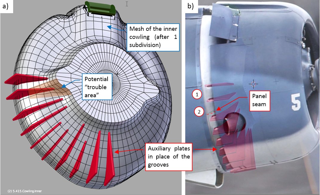
Figure below shows the initial stage of this work. For each groove I created an auxiliary “plate” (Figure “a”, below) and adjusted their thickness and locations to the reference photo (Figure “b”, below):

Each of these plates is a simple, four-vertex plane. Its thickness is created by the Solidify modifier, and the rounded edges – by a multi-segment Bevel modifier. As you can see in Figure “b”, above, I set their locations and rotations, so each of their cross-sections with the cowling fits the edge of a groove visible on the reference photo. It occurs that the distances between the grooves are not uniform – as you can see, comparing the distances (1) and (2) in Figure “b”, above. (Note that there is a panel seam within range (2) – I think that this is the reason of this additional “spacing”).

I also thought about the mesh topology. In the optimal case:

  1. each plate should cross only the perpendicular edges of the cowling panel. Eventual single radial edge along the middle of the plate is also acceptable;
  2. there should be at least single “radial” edge on the cowling panel between two subsequent plates;

To fulfill requirement 2, I had to make the initial mesh of the cowling panel denser (subdividing each face once, by applying the Subdivision Surface modifier). You can see the resulting mesh in Figure “a”, above. I also marked there the potential “trouble area”, where the plate is crossed by the skew edges. It is always better to know such a thing in advance.

(Before applying the Subdivision Surface modifier, I also had to apply the original Bevel modifier, which rounded the gun throughs edges. Thus, at this moment this cowling object has just a Mirror modifier in its modifier stack).

In the next step I modified the cowling mesh, creating some space for the grooves:

I redirected the edges in the “trouble area” marked on the picture. I also rotated by a fraction of degree many of the other radial edges, so that they go straight in the middle of the plate, or run along its side, far enough for the rounded edges of the groove. It is hard to notice these results at first glance, but this is the key work which determines the quality of the final effect.

Once the mesh of the cowling was updated, I removed from the plates their Bevel modifiers and applied the Solid modifiers, converting their meshes to “boxes” of fixed width (0.7”). (The only purpose of the Bevel modifiers was to round the plate edges for comparison with the grooves on the reference photo).

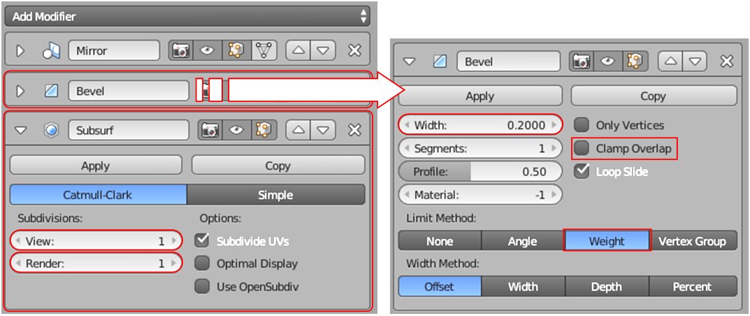
Before I started “chiseling the grooves”, I added to this cowling panel a new Bevel (weight) modifier, and a Subdivision Surface (1) modifier. Figure below shows the current state of the modifier stack of this model part:

These two new modifiers will round the edges of the grooves. The size of the Bevel (0.2”) is appropriate for the width of these grooves (0.7”). Of course, in your case you have scale these dimensions proportionally for your groove width.

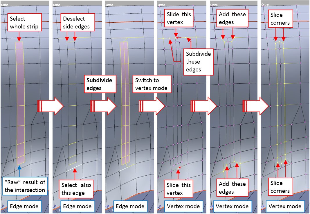
To cut out a groove contour, I joined (Object:Join, or [Ctrl]-[J]) the plate object with the cowling, and selected all of its six faces (Figure “a”, below):

Then I invoked the Mesh:Faces:Intersect (Knife) command, obtaining the initial edges of the groove (Figure “b”, above). The Intersect (Knife) command produces some overlapping vertices, which I quickly fixed, selecting all of them and invoking the Mesh:Vertices:Remove Doubles command. I also removed the “cutting box” (I do not need it anymore). In the last step I adjusted the ends of this “strip”. I created four additional vertices (two of them at each end), to add four additional edges (Figure “c”, above). (I created these new vertices by selecting the corresponding edges and invoking the Mesh:Edge:Subdivide command). Finally I shifted the corner vertices of this strip inside, using Mesh:Vertices:Slide command ([Shift]-[V]).

Then I use the Mesh:Transform:Shrink/Fatten command ([Alt]-[S]) to move the central vertices of this groove down, each along its original normal direction:

This groove has width of 0.7”, so I shifted its vertices downward by 0.4” (I found this proportion optimal). Then I assigned the Bevel weights to round the edges of this groove. I set the weight = 1.0 to the central edge, and weight = 0.5 to the side edges (Figure “a”, below):

Figure “b”, above, shows the resulting surface.

I repeated this sequence of operations for each groove. When the intersection produced a contour without the central edge, I used the Mesh:Edges:Subdivide command to create a new one:

Figure below shows the finished grooves on the SBD-5 and SBD-3 cowlings:

(The SBD-1 uses the same inner cowling as the SBD-3).

After this work, I had to refresh the UV maps of the modified elements. Figure below shows my test render of the SBD-5 cowling:

As you can see, I removed the NACA cowling from this model, so that you can evaluate the ultimate result of my work.

You can download the model presented in this post from this source *.blend file. To reduce its size, it is stripped from the texture images.

3 Likes

sorry for not replying sooner. yeah, I did use group instances on several occasions, like cannons and deadeyes, but unfortunately there aren’t many repeatable objects on the ship. pretty much everything is unique due to curved shape of the ship. mirror modifier is my main poison here.

man, amount of detail present on the plane is amazing. you’re going for automotive CAD quality here…

You could by now write a couple of master-class books on CG modeling at this point.

It’s no wonder why people asked you early on about copyright licensing.

heraSK - thank you, and congratulations for your beatiful ship! It is much more complex than my model…

Than you! In fact, I already published a thick book on this subject in 2015. When I finish my daily busines project (in the mid-2019) I will have to sit down and rewrite this book for the Blender 2.8 and the newest GIMP. I think that it will take over a year…

A small off-topic note:
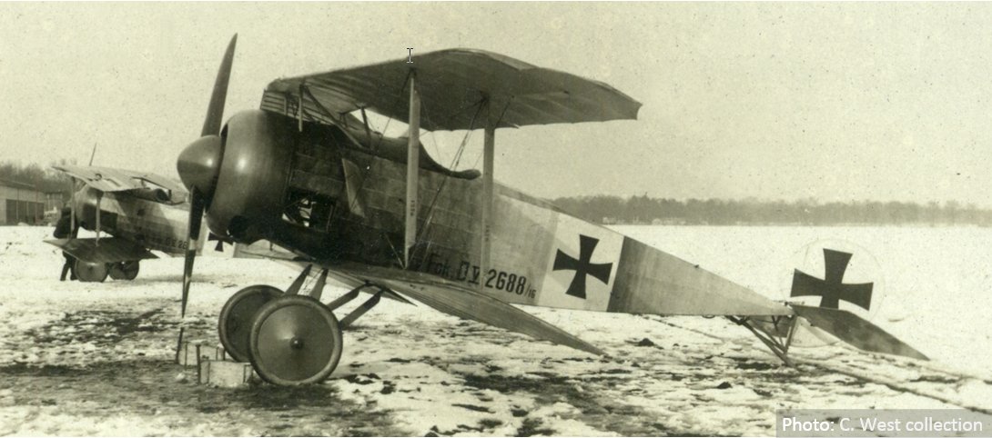
this winter I was busy with my daily business and took a break from the SBD model. However, in February and March I spent few Sundays helping in another project: recreating the Fokker D.V biplane, used in 1917 as an “advanced trainer” by German Air Corps:

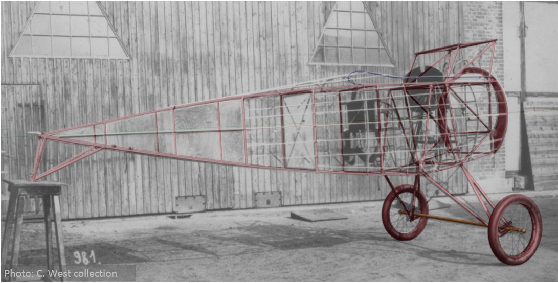
My part was recreating the geometry of this aircraft, especially its fuselage frame made of steel tubes. All what we had was a dozen of various archival photos, a poor general drawing, and the landing gear dimensions. In this case I had to turn the available photos into the precise reference, as I did for the SBD, then use them to determine the required geometry details:

Doing it, I also made a “discovery” about wing geometry of this airplane. See details in this post.

2 Likes

Important update about this SBD project: thanks to C West help, I identified a microfilm roll set of the original Douglas documentation for the SBD/A-24. In June I ordered its copy from NASM and now I am waiting for these materials. When I got them, they will be scanned by a local service company which scans various museum archives. This is not cheap, because the only possibility is to scan all microfilm frames (and pay for each frame, of course - I estimate that this set of seven microfilm rolls contain about 5500-6000 frames). Then I will organize these scans for quick use as the reference materials.

In the meantime, I am going to update my P-40 model, also using original blueprints. I already bought their scans. See this blog post about my experiences on this subject.

Great job on the SBD and P40. I’ve built a few airplane models. Mostly in Lightwave and Modo. Unfortunately they were for TV shows so I did not have time for a lot of research. But I understand the frustration of trying to find good references and plans that are correct and match each other.
I know your working on updating your Aircraft modeling book to 2.8. How well does the techniques in current book, for 2.79, translate to blender 2.8?
For your main fuselage etc are you using subdivision surfaces or curves modeling? And what tools are you using to smooth them out?

Thank you!

The basic concept of the workflow remains the same: I will still use the subdivision surfaces as the “smooth” modifiers of all of the base meshes in this model. Some changes: I will use Solidify modifiers everywhere to imitate the sheet metal thickness, and Boolean operations for certain openings (now they produce cleaner mesh). Adapting to the Blender 2.8 possibilities, I will use hierarchical layers to better organize the model structure, and multiple Empty images for the references. Of course, I will show some quick effects with the new internal renderer, adding some fancy materials - like polished aluminum or the glass - to this “gray” model. Because the access to the original blueprints is extremely rare (and their use requires much time) I will remark about these references in a “verification” paragraph, added at the end of each section. It will compare the model built based on the classic scale plans and photos with the more precise reference from the blueprints, and show the differences and eventual hints how to avoid them in the future.

1 Like