Great work. And great presentation here, too!
Thorst - thank you!
Today I would like to describe a new method of using reference photos.
During the previous weeks I formed two main elements of my model: the wing and the main part of fuselage. As you saw, I could not resist myself for adding some details to the wing (like the ribs and spars of the flaps).
Now I think that this is a proper time to stop modeling for a moment and compare the shape of the newly modeled parts to the real airplane. If I find and fix an error in the fuselage shape now, it will save me from much more troubles in the future! If I find an error in the wing shape – well, I will have more work, because I already fit it with some details which will also require reworking… You will see.
The idea of using photos as a precise references emerged from the job that I did two years ago. One of my colleagues asked me if I can recreate the precise shape of the stencils painted on an airplane. He wanted to determine details of the numbers painted on the P-40s stationed in 1941 around Oahu. He sent me the photo. I started by fitting the 3D model to this historical picture, finding by trial-and-error the location and focus of the camera (as in figure below):
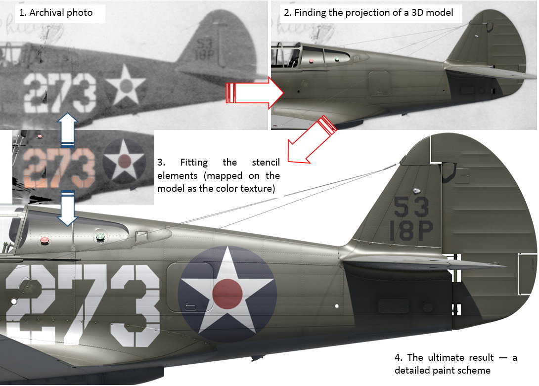
Then I made the model surface completely transparent. I placed the opaque drawing (texture) of the large white tactical numbers on its fuselage, and the black, smaller, radio call numbers on the fin. I rendered the result over the underlying photo, finding all the differences. Then I adjusted the drawing and made another check. After several approximations I recreated precisely shapes and sizes of these “decals”.
The key point in this process was to recreate the location and focus of the camera that was used to make the particular photo. Now I realized that it is possible to use the photos in the same way as precise references for my model. All I needed was a high-resolution picture.
I decided to begin with one of the archival photos of the SBD-5 from VMSB 231, made in spring 1944 (the original photo below is 2127px wide):

To find the camera projection that fits the model into airplane contours on the photo, you have to coordinate the location of the camera and its direction (I used for this purpose an auxiliary “Target” object). Yet another parameter to be adjusted is the camera lens length:
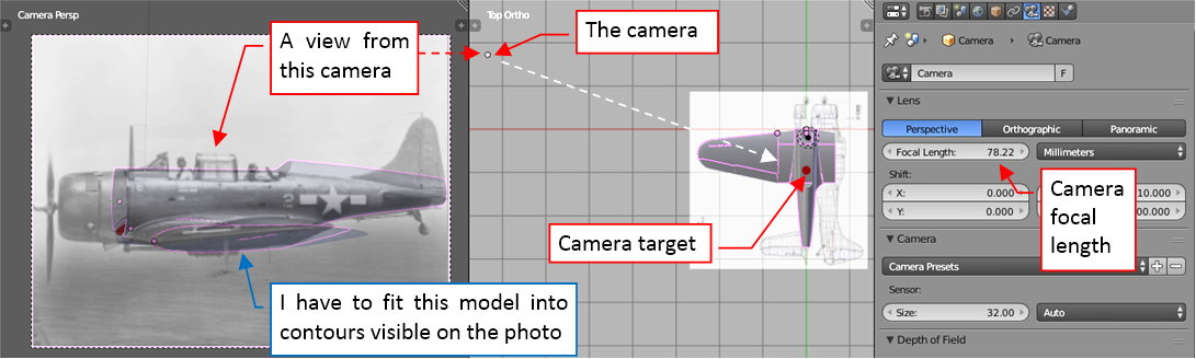
The whole process is an iteration: I started from a rough first approximation (as in figure above). Then I enhanced it, gradually determining the ultimate camera and target location, as well as the focal length.
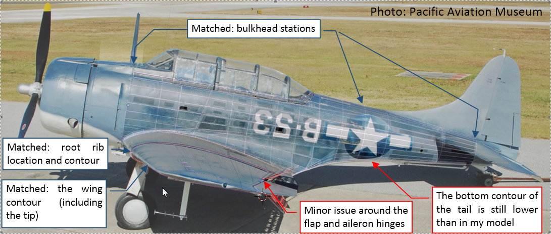
In this process I based mostly on the elements which dimensions were determined by the “hard” evidence. It pays off that I placed most of the the fuselage mesh edges along the original bulkheads and longerons. (I will also benefit from this during further stages of my work). I was quite sure of the bulkhead stations because they were set according the original diagram. Thus I started by fitting to the photo the fuselage between the firewall (station 0) and the last bulkhead (station 271). Then I tried to find the proper camera focus that fits the middle bulkheads to the rivet seams and panel lines which are visible on the photo:
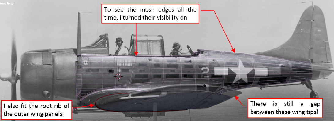
I was also able to fit to this photo the root rib of the outer wing panels. However, I could not match the position of the wing tip! When I fit this tip to the photo, the fuselage deflection was wrong. Otherwise, as you can see (in the figure above) the wing tip of the model was a few inches below the tip on the photo. I started to wonder why I have such a problem…
Figure below shows the best projection I was able to find. The fuselage bulkheads fit well the seam lines from the photo. It seems that the bottom contour of the tail was somewhat lower than in my model:

The only weak point is the different elevation of the wing tip. I cannot say that it had a greater dihedral, because it was dimensioned on the original general arrangement diagram (7⁰ 30’ along the upper wing contour, in the front view).
Finally I came to conclusion that what I can see on this photo is the elastic deformation (bending) of the loaded wing! This aircraft here is depicted in the flight, right? This means that these wings are carrying the load of about 4 tons of its weight. Their structure was stiff, but not absolutely rigid: every beam deforms (more or less) under the load. The airplane wings are not the exception: while flying in an airliner (like Boeing or Airbus) you can observe how their wing tips bend in the air. Of course, the relatively short, wide wings of the SBD Dauntless were much more resistant to such deformations. Nevertheless I think that we can trace the slight bending of this wing leading edge on the other shots of this airplane. For example, the white sun reflection on the photo in figure below allows me to reveal this dynamic deformation:
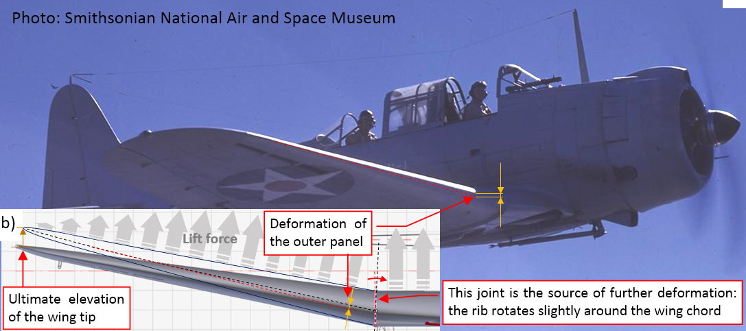
We can see here the bending of the outer wing panel. However, there was another deformation: in its joint with the center wing. The root rib under loads slightly rotates around the wing chord, which elevates the wing tip even further (in figure “b”, above). I suppose that the center wing was much stiffer (it had thicker airfoil and shorter span than the outer panels).
Using a side photo of a flying airplane, always try to estimate the elastic deformation of its wing, especially the wing tips! Usually such a deformation makes these photos less usable as the precise reference for a 3D model.
Frankly speaking, this conclusion was a little surprise. I have not noticed such a deformation before — maybe because I was mainly focused on the WW II fighters? Fighter wings are the stiffest ones…
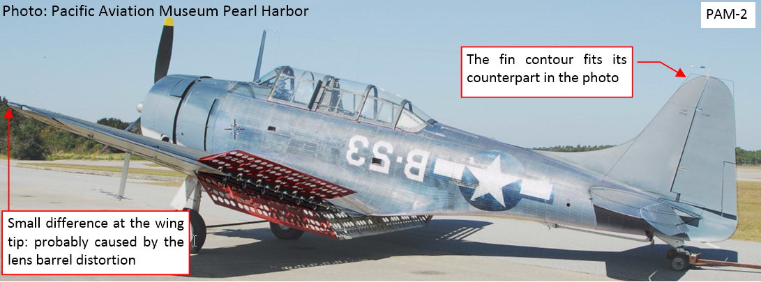
In the airplane standing on the ground the wing deformation is minimal, thus such a picture suits better the reference purposes. Ultimately I decided to use some of the photos published by the Pacific Aviation Museum on flickr.com. Figure below shows the result (I had to flip this photo from left to right because I modeled the left wing):
As you can see, the wing perfectly fits its contour in this photo. I have found that the left aileron airplane was rotated upward by about 4⁰. I can see some differences in the hinge location of the upper wing flap (on the photo it seems to be placed at somewhat different angle, and shifted to the rear). The contour of the aileron bay also seems to be a little bit lower. On the fuselage you can see that the bottom contour of the tail is placed lower than in my model — confirming the observation form the previous photo.
When you find deviations as these that I have found in the aileron and flap hinges, it is always a good idea to check them on another photo. Thus I fitted my model into a different picture from the same PAM photo stream on flickr:

In this case I opened the wing flaps, because their straight contours helped me in precise positioning of my camera. It was possible to fit the bottom flaps to this photo (I just discovered that in this photo their deflection angle is 40⁰, while according to the specs it should be 42⁰). I was able to verify locations of their ribs and spars. (It occurs that these ribs, set according the stations diagram, are in the proper places). However, the upper flap did not fit properly into its contour in the photo. It was only possible when I shifted its hinge to the rear, placing it as in figure above. In this way I confirmed that these wing elements require corrections.
After these initial findings I decided to verify both: the wing and the fuselage, to fix all the differences I would find. Of course, it required more photos. Matching the model projection to a single picture takes me several hours of work (usually — one evening). I assigned to each of these pictures a separate camera (as well as the camera target object). Their names are three-letter shortcuts of the source photo followed by the ordinal number: thus PAM-1 means “Pacific Aviation Museum – 1.jpg”, UND-1 is “Unidentified – 1.jpg” and so on. I think that these reference pictures will be also useful in the future stages of this work. Switching between these cameras requires several steps: you have to type the path to the corresponding photo, as well as to alter the scene renderer aspect ratio. To facilitate this operation I created a dedicated add-on, which allows me to switch between these pictures with one click:
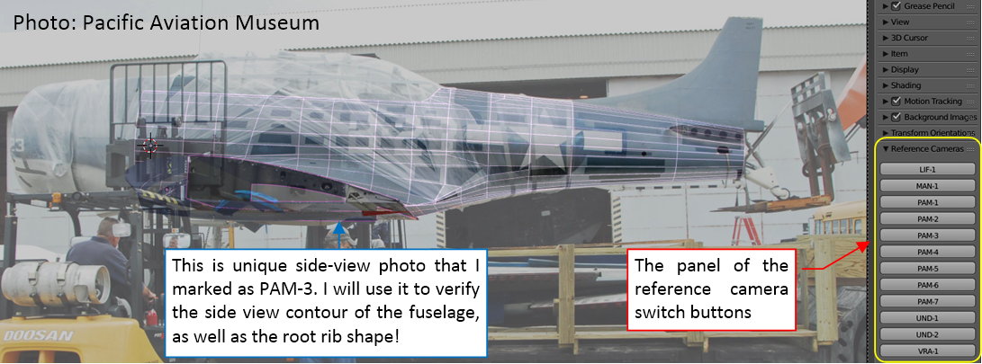
The ability to immediately switch between various reference photos definitely makes the difference! It encourages to study the same fragment from all possible sides.
The photos can be extremely useful reference, but they do not replace the traditional scale plans. First you have to create a 3D model that is close enough to the real shape, using the plans. Then you can project such a model onto a high-resolution picture for the further improvements.
In this source *.blend file you can evaluate yourself the model matched to the first picture from the Pacific Aviation Museum.
Last comments to my post #86 (I had to shorten it to fit into 10k characters limit):
To effectively match a 3D view projection to the photo, you have to be sure that at least some points of your model are in their real locations. In the case of my Dauntless model these “fixed points” were:
- Positions of the fuselage bulkheads (I read them from the stations diagram);
- The basic trapezoid contour of the wing (deduced from the general arrangement diagram dimensions);
- Positions, shapes and sizes of the root rib (the rib at the joint between the center wing and the outer wing panel. I deduced its chord and spatial location in relation to the firewall from the general arrangement diagram dimensions, while its shape is declared as NACA-2415 airfoil);
Then you can precisely determine the location of the camera and its lens by matching these elements to the photo.
In the next two posts I will write about the results of this verification. In the first one I will describe the errors that I found in the shape of my fuselage. In the second post I will describe the differences that I found in the wing. Sometimes fixing these minor errors require several hours of work… But this is why we are the modelers (“a slightly different human being” :)).
errors on reference pic
some times the X and Y scale are not the same
or there is a small rotation or distortion !
I mean not 100 % reliable !
even when you are lucky to get photo
there is the perspective effect that can distort the image
and then the human factor !
happy bl
I know that this is a lot of work, and you do it awesomely!
However, I would be careful with this kind of photo-matching because of two main reasons.
The first one is that Blender to my knowledge does not allow you to adjust the lens distortion. Lens distortion can make a huge difference if your subject fills almost the entire field of view. When you try to match the model to the photo you usually take the longest baselines as a first guess (for example from the front to the end of the tail), but a lot of your interest will be in between. This means that you calibrate your camera parameters for the outer regions, but the lens distortion will make the central region of the picture not neccessarily matching to the model. So you may find errors with the comparison which are not real.
The second one is that the parameters may be strongly degenerated. A slight error in your focal length can be compensated by moving a bit away or towards the object. Fitting this by hand may not give you the objectively best fit.
I would imagine that for example your difficulty to fit the wingtip on the one picture is caused by the wrong focal length, which may also be made worse by some lens distortion.
I have tried automated photogrammetry some months ago and found that lens distortion really changes things a lot. Without it, things just don’t match, but with it, you get exceptionally good results.
Before, I did it the exact same way as you do here, but with the exception that I knew the real shape very accurately by independent informations (blueprints, measurements and an independent 3D-scan) which I used to draw a CAD-model and exported it to Blender. I was unable to fit the camera position and focal length for both the center of the picture and the outer regions. Lens distortion is just such a big issue, as is the precise focal length.
I would really advise you only to use it with most care, and only use pictures with long focal lengths (100mm+).
Best regards,
Thorsten
Thorsten, I would like to thank you for your tips!
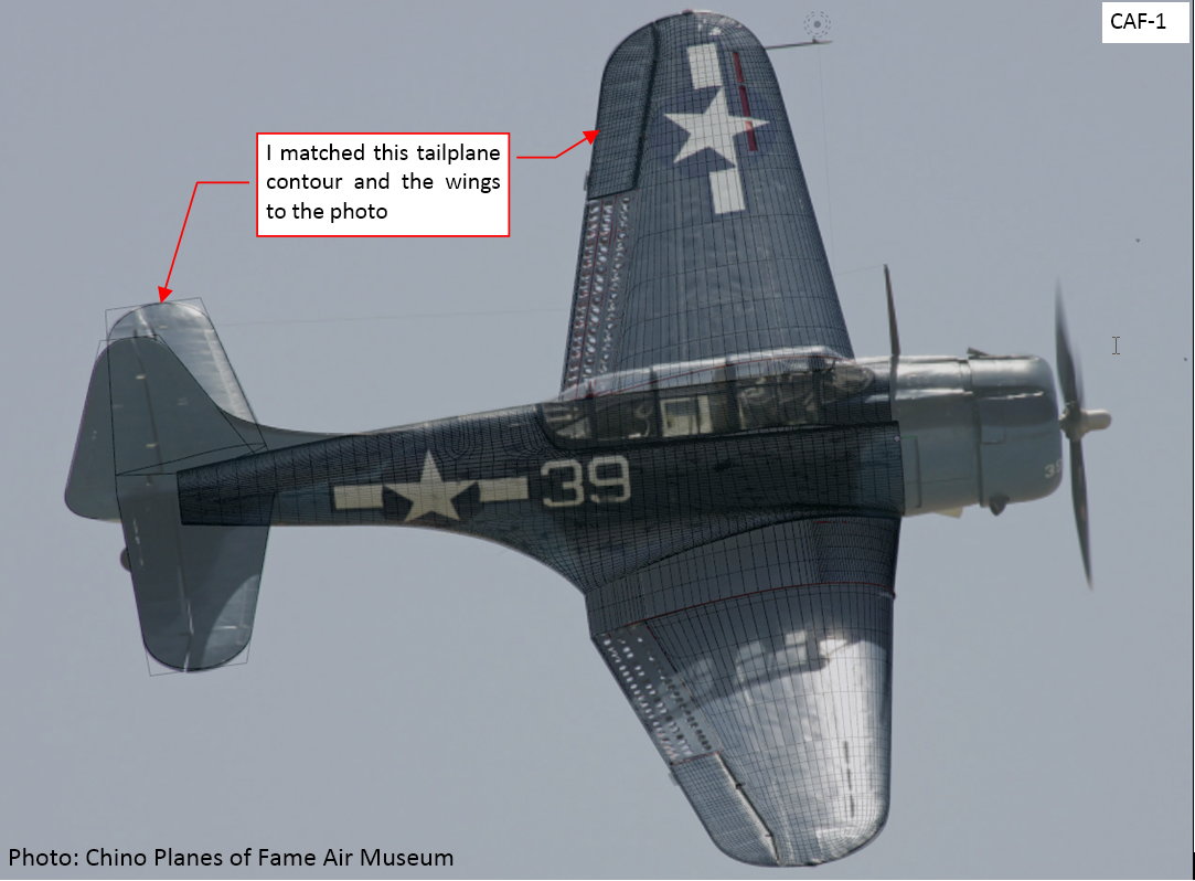
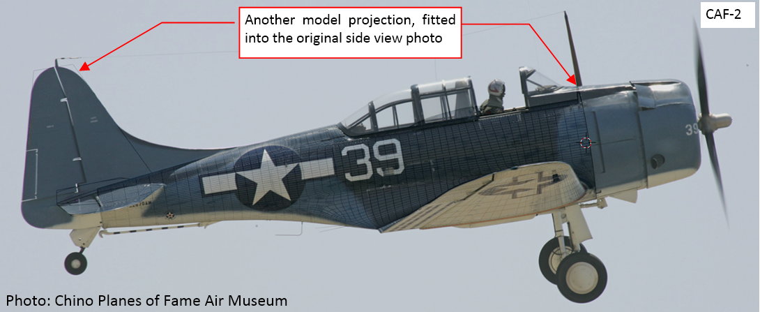
Indeed, I did not notice that Blender camera has no barrel (and any other) distortion! I immediately dig into the nature of the lens distortion, using the documentation available on the web. I will try to use Hugin to revert barrel distortion of the photos from Pacific Air Museum (the straight joints on the airfield surface offer a chance to calibrate the reverse operation). Simultaneously, following your second suggestion have given a try to the Chino photos that I used at the beginning of this thread. They have much lower resolution (1280x124px), but all were made with a 400mm lens:
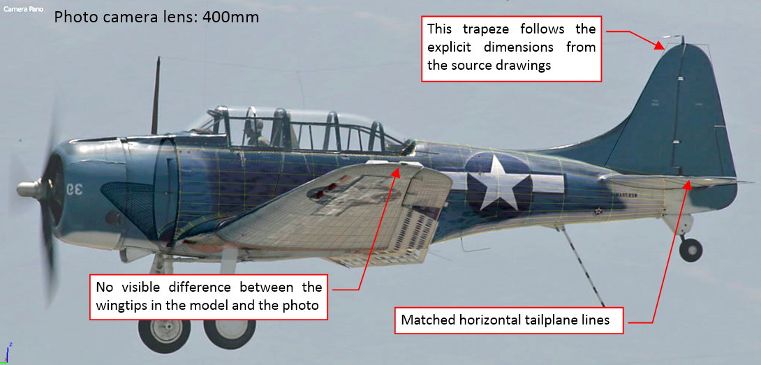
To make a better match, I added to the model basic contours of the empennage. As you can see in the photo above, I was wrong about the wing tip: the Dauntless wing is much more stiff. Thus the only explanation for the difference described in the previous post is the barrel distortion of the photo + eventual deformation of the phisical negative (for example – during drying?).
However, it seems that the differences in the photos from Pacific Aviation Museum are not big. Thus I could already identify several differences in my model, which are confirmed by all matched photos, made from different angles. I will describe them in the two next posts.
Wow, very impressive presentation.
I’m glad that it helped a bit. Your work is fantastic, I could watch it all day long.
keseyrage, thorst - thank you!
Currently I am using the method discussed in previous post to verify teh geometry of my model. It is a good idea to do it when there are no additional details. All the differences that I will find now will save me a lot of troubles in the future. For example — what if I would find that the base of the cockpit canopy in my model should be somewhat wider, when this canopy was ready? I would have to fix both shapes: the canopy and the fuselage. And what if I would already recreate the inner fuselage structure — the longerons and bulkheads — before such a finding? I would also have to fix them all. This is a general rule: the later modifications require much more work than the earlier ones! Thus I have to check everything when the model is relatively simple. You can compare the differences I will find in this post with the plans I published earlier in this thread: they contain various minor errors! Just as every drawing.
Last week (see my post from 2015-12-06) I discovered that the bottom contour of the tail was somewhat lower than in my model:
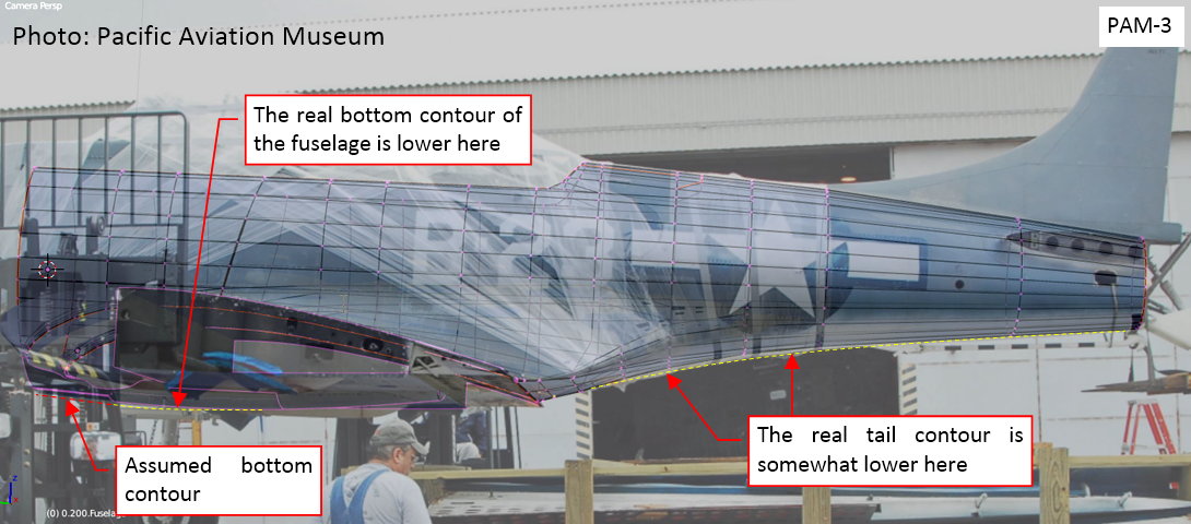
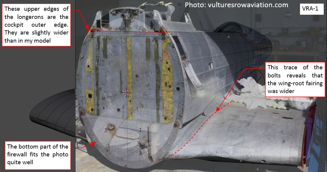
The main problem with mapping the tail shape was that its bottom part behind the wing was wide and completely flat. On every photo that I have the airplane is more or less deflected toward the camera, so the precise bottom contour of the SBD tail in the side view is an average of multiple estimations. That’s why it can be wrong on my scale plans! I also found a minor difference in the forward part of the fuselage below the wing. However, its forward part on the photo above is obscured by the truck. Nevertheless, I guess that the forward part of this cover it had a straight side contour, located minimally below than this contour in my model. To check this I mapped another photo of the firewall:
This photo confirms my observations from the side view picture. Although the bottom of the fuselage here is lacking the bottom covers, the corner of their mounting flange “touches” the bottom contour of my model. It means that the real contour was somewhat lower, more or less along the yellow line that I sketched on this picture. However, you can see here another difference: the upper part of the firewall is little wider than the elliptic contour that I assumed (It seems that the shape of the firewall was not an ellipse, as I assumed in one of the previous posts).
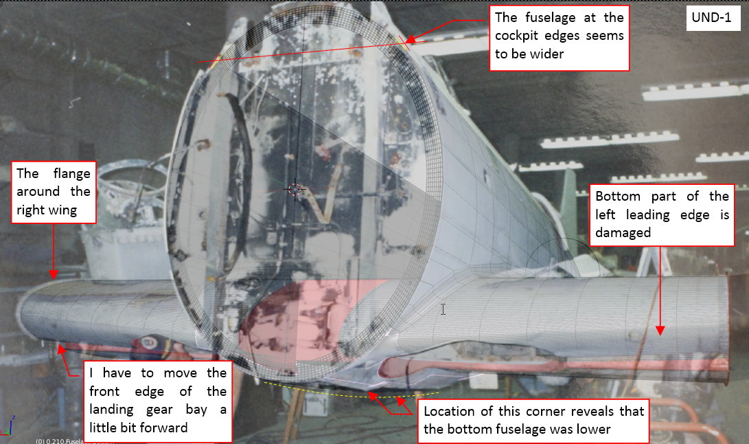
To make sure that this is not a mistake in the matching the model and the photo (or the effect of a barrel distortion), I also used another picture, from other restoration:
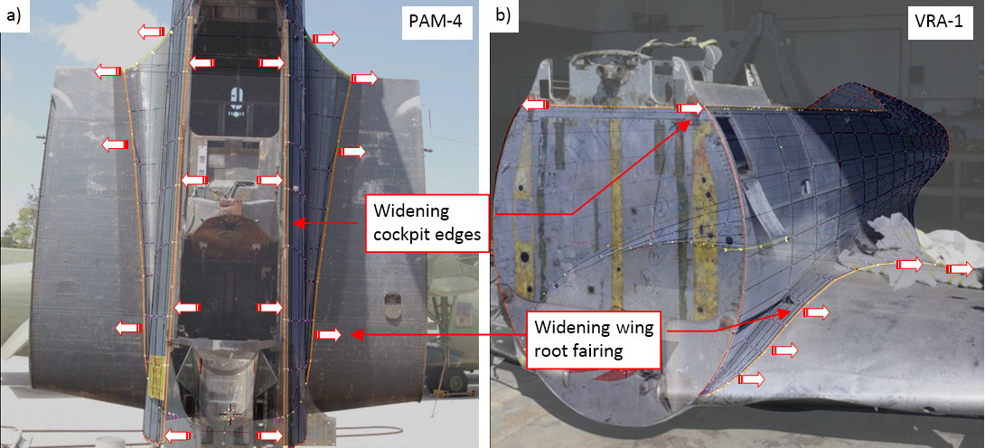
The photo above confirms that the fuselage was little bit wider at the cockpit edges than it is in my model. The trace of the bolt seams on the wing reveals another difference: the wing root fairing was also wider (at least its forward part).
To make sure that this difference is true, I have to find it on every photo that I map onto my model. Thus I mapped two other photos. They come from Pacific Air Museum. I can use them to verify the width of the mid-fuselage and the span of the rear part of the wing root fairing:
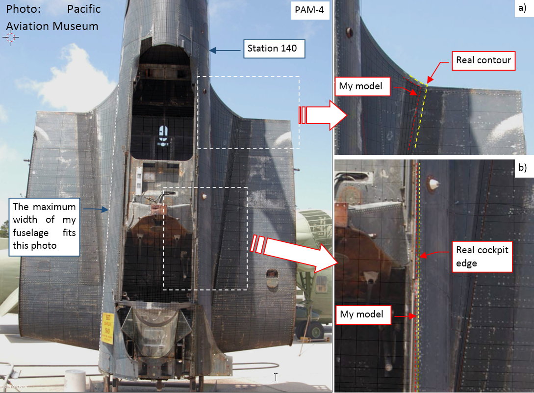
The good news is that the maximum width of my fuselage perfectly matches the photo (a good luck!). I found that the width difference at the cockpit edges found at the firewall is (approximately) constant along the whole length of the cockpit (figure “b”, above). It disappears behind the cockpit (i.e. in the front of station 140). The wing root fairing was somewhat wider at the trailing edge (figure “a”, above).
As usual, I used another photo to confirm these findings:
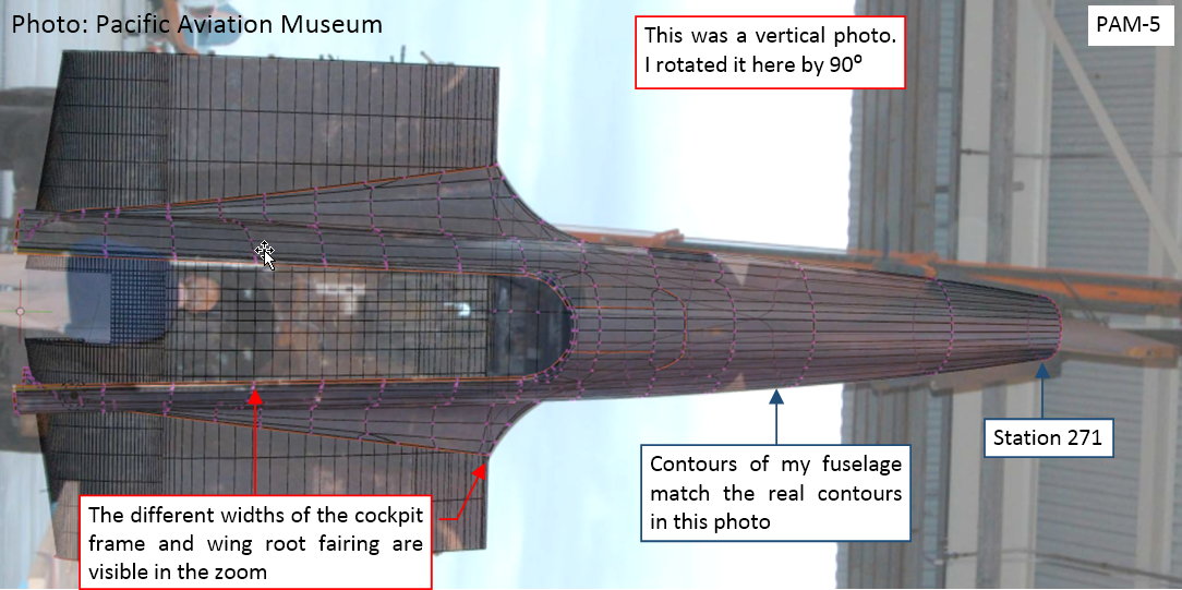
Because this photo depicts the whole fuselage, I had to check these details using higher zoom factors. This photo confirmed what I have found in the previous one. In addition, it seems that the width of the fuselage in my model matches the real contour of the tail up to station 271.
Once I confirmed all these differences, I had to fix my model.
The wider wing root fairing behind the trailing edge can create impression of lower tail contour on the photos taken from the side (in the first photo in this post). This is because none of these photos is an ideal side view shot. In each of them the camera was located above or below the fuselage centerline. That’s why I decided to begin by fixing these differences in the fuselage width:
Once they were corrected, I could fit the side contour, matching it to the horizontal photo of the tail:
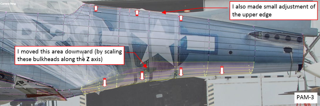
As you can see in this picture, I also minimally modified the upper contour of the fuselage. (Because the upper arc of its cross sections was looking like a part of a flat ellipse, while it should be a regular arc).
Figure below shows the ultimate differences between the reference drawings I created several month ago and the contour obtaining from matching the 3D model to the photo:
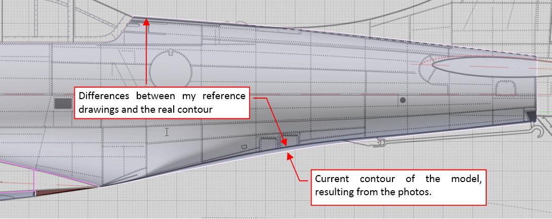
As you can see, nobody is perfect, so I also did some mistakes. However, I was aware that the bottom contour of the fuselage was a guess: I did not have any photo where it was directly visible. All the pictures were taken from below or above, leaving some space for various assumptions (which often results in some errors).
Finally I fit the covers on the bottom fuselage (below the wing) to their contours in the photo:
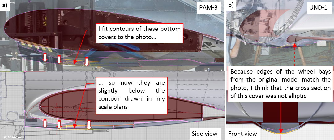
I moved slightly downward the forward part of these covers. As you can see in figure “a”, above it was a relatively small difference. Initially I assumed that the cross sections of this bottom fuselage were elliptic arcs. However, in such a case, for the given width and height (from the side and bottom views), the edges of the wheel bays would appear a little bit lower than those visible in the photos. Thus I think that the contour of the middle cover in the front view had a slightly different shape (as depicted in figure “b”, above).
In this source *.blend file you can evaluate yourself the model from this post.
While matching the model to the photo (PAM-3) taken from left side, I noticed slight differences in the wing rib shape: it seems to be a little bit thicker than on the picture. I will analyze this and other differences of the wing in the next post.
In this post I will continue verification of my model by matching it against the photos. This time I will check the wing geometry.
In the first photo from the Pacific Aviation Museum (in my model it is marked as PAM-1) I identified several differences:
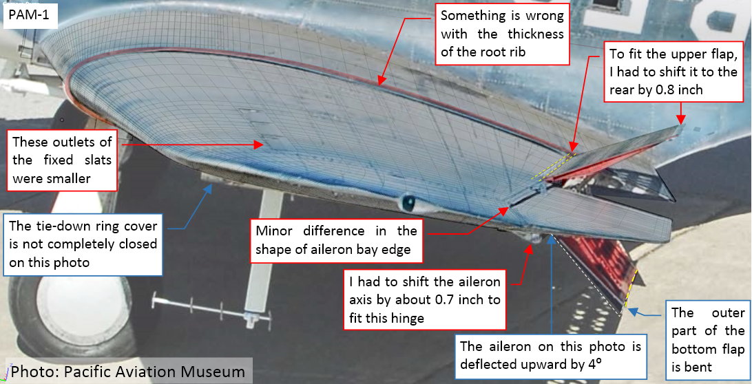
First I noticed that the hinge of the upper flap in my model is in the wrong location (I had to shift it forward by 0.7 inch). The upper edge of the aileron bay had slightly different shape on this photo. In this picture the tip of the aileron (the point lying on the wing tip outer edge) is located in the front of the corresponding point in my model. (The difference is less than 1 inch). Surprisingly, the inner (root) rib of the aileron seems to be a little bit higher in my model than on the photo. I can see also similar difference in the root rib of the outer wing panel. Location of the aileron bay upper edge on this photo can also be interpreted as located below the corresponding edge in my model. Does it mean that I made an error in forming this wing? The last visible difference are the outlets of the fixed slats. According the photo they were smaller and set at slightly different angle.
To check the differences in the wing thickness and the details around its trailing edge, I matched my model to another photo:
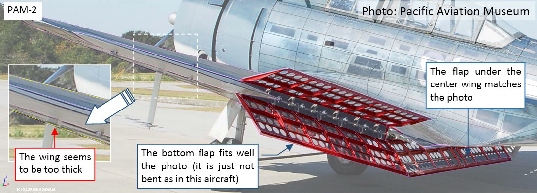
I opened the wing flaps to better match the projection of my model to this photo. I used the shorter edges of the flaps to precisely determine their deflection. The bottom flaps fits well into this photo (if you take into account that in the depicted airplane the outer flap is bent). To fit the upper flap I had to shift it by 0.8 inch, as shown in the previous photo (as in the first figure in this post). This confirms that there is a difference! What is interesting, the wing on this photo is also slightly thinner than in my model — which confirms that I made a mistake in recreating the shape of its ribs.
As I wrote, I was convinced that I properly recreated the airfoil shape. I used the original coordinates of the NACA-2415 (and NACA-2409) airfoils (as you can see in figure “a”, below)! Thus I used another, side photo (PAM-3) to check this finding:
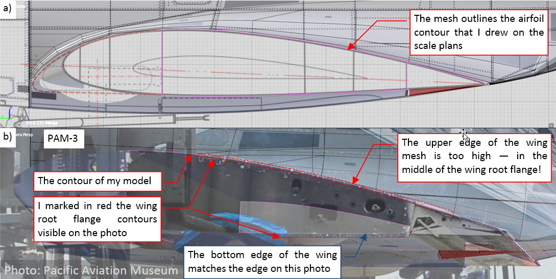
The overall chord of the wing rib in figure above seems to be OK (luckily, on this photo you can see the fragment of the leading edge between the truck forks). The chord of its bottom flaps in my model also fits corresponding chord on the photo. However, the upper edge of the root rib in my model seems to be too high (by about 0.3 inch). I can see clearly that it occurs in the middle of the upper flange of this rib. On the scale plans this difference corresponds to just half of the contour line width! That’s why we have to use photos: the drawing conventions alone make the scale plans not as precise as we wish… The PAM-2 photo reveals that this difference (maybe somewhat smaller than at the root) extends over the whole wing span.
Well, so I had to fix it. While lowering the upper part of the center wing was relatively easy (figure “a”, below), I had also to modify all the adjacent objects — ribs, spars, and the fuselage
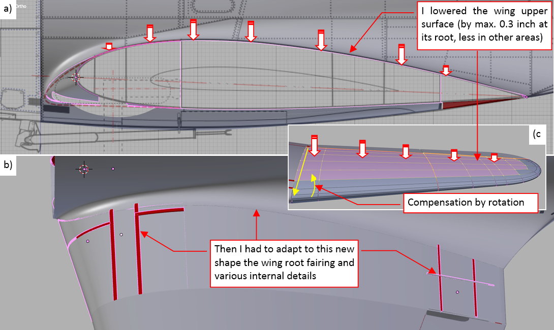
The more difficult was to make similar modification in the outer panels. The difference was smaller at the wing tip. To preserve the straight lines of the spanwise mesh edges I moved the whole selected area down by 0.3 inch, then compensated the difference at the wing tip by small rotation around the wing root chord. (I had to separately rotate each of these “longeron edges”). Of course, then I had to make a lot of minor compensations in the upper flap and the aileron contours.
However, I had to modify these trailing edge details anyway, following the other findings from the photos:
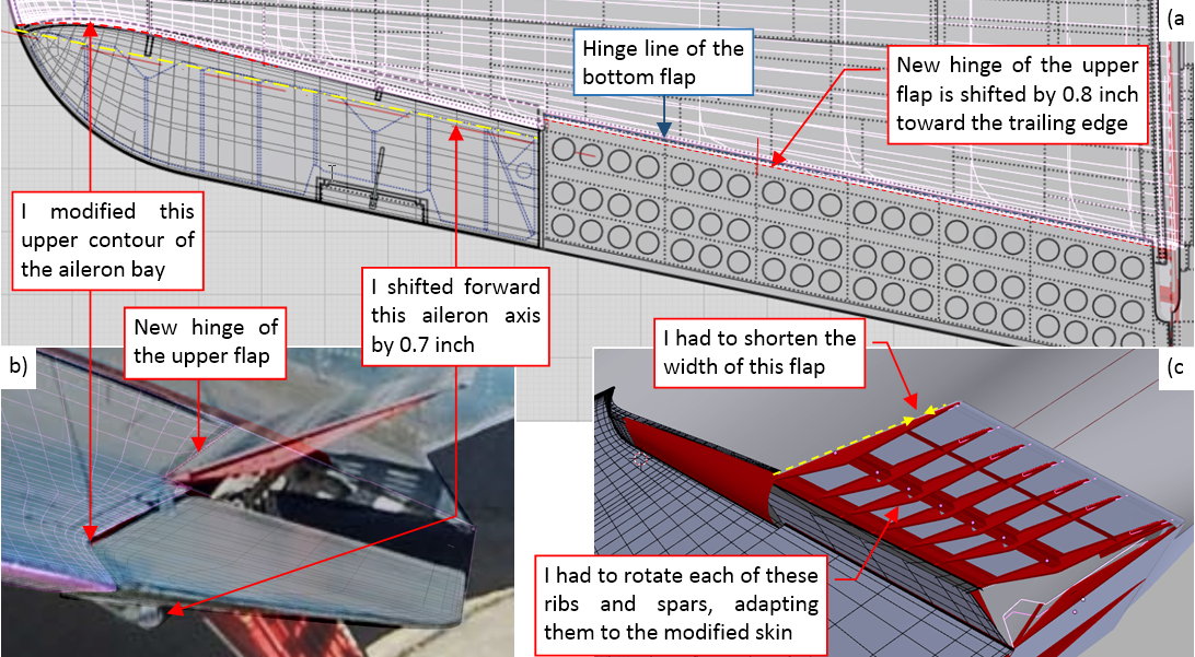
In this modification I had to revert the changes I made three months ago to the aileron bay edge (in my post from 2015-09-12 about details of the outer wing panel). It was the wrong location of the flap hinge, while the aileron bay edge should be in the place depicted on the reference drawings! In fact, drawing these scale plans I assumed that the hinge of the upper flap was directly above the hinge of the bottom flap. (You cannot see the difference on the most common, horizontal photos). Now I know that it is shifted away from the auxiliary rear spar by about 0.8 inch. After this modification I had to shorten the chord of the upper flap and rotate its ribs and spars, adjusting them to the altered directions of the flap skin. It required a few additional hours…
Once I finished with the trailing edge, fixing of the outlets of the fixed slats was easier. I just had to modify the shape of the “cutting tool” auxiliary object, used in their Boolean modifier:
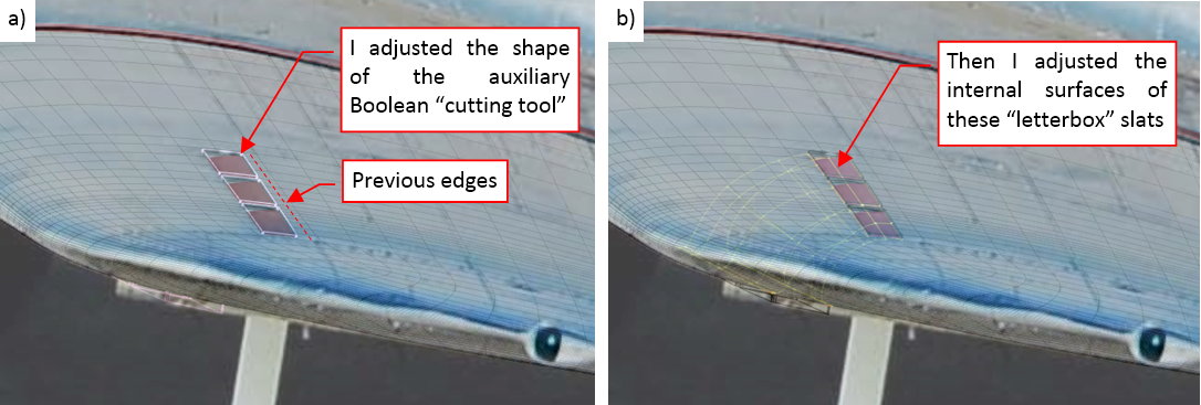
Then I adjusted the slat internal surfaces, fitting their upper edges to these modified openings (as in figure “b”, above).
If I encountered such surprises on the upper wing surface, what do I find on the bottom of the wing? I started by examining the outer wing panel:
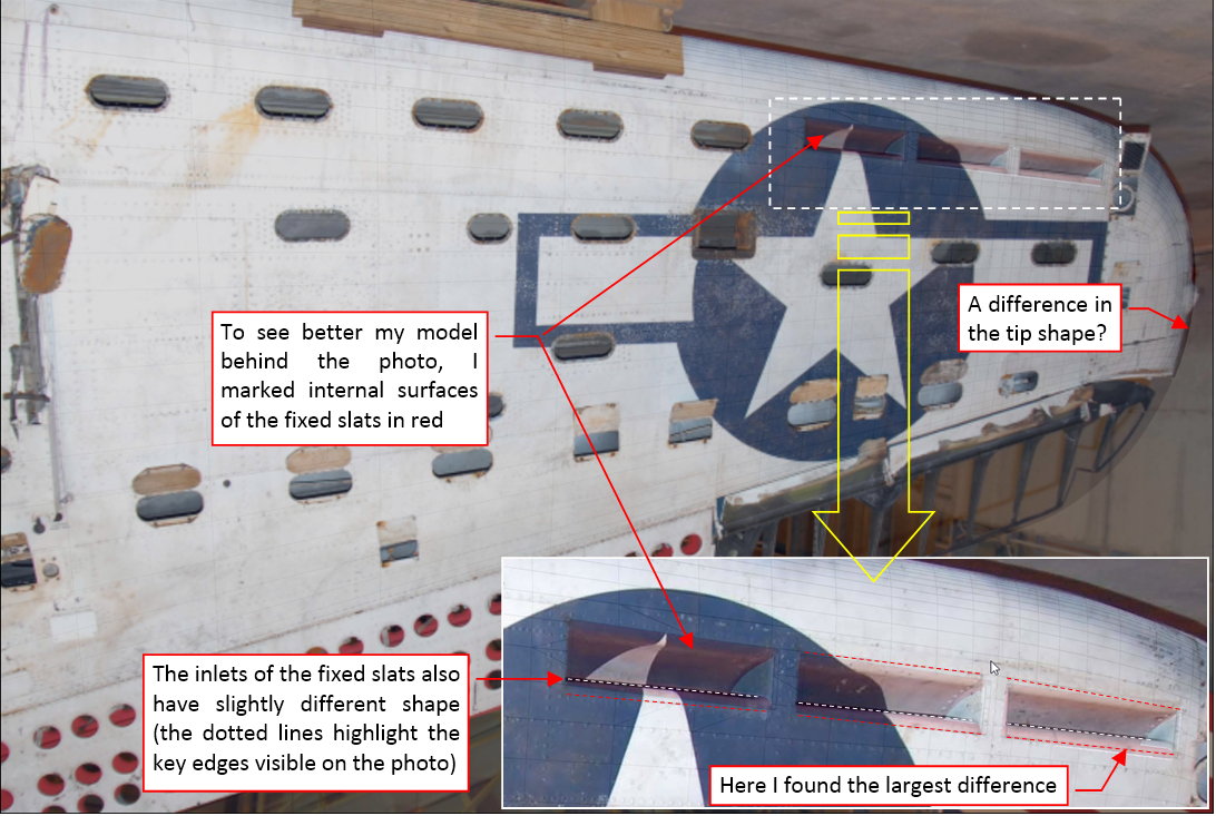
It was surprisingly difficult to find an appropriate projection for this wing — I badly missed the fuselage here! (It would allow me to better determine the proper direction of the camera). The barrel distortion of this photo could also have some influences on this matching. Fortunately, it seems that my model fits better this area of the real wing. The first difference I found was in the fixed slats: minor adjustment of their direction and sizes. I fixed them in the same way as their outlets on the wing upper surface (I will not bother you by describing the details). Another difference is more subtle: it seems that the real wing tip has slightly different shape than in my model!
Of course, I had to check it on another photo, taken from another direction:
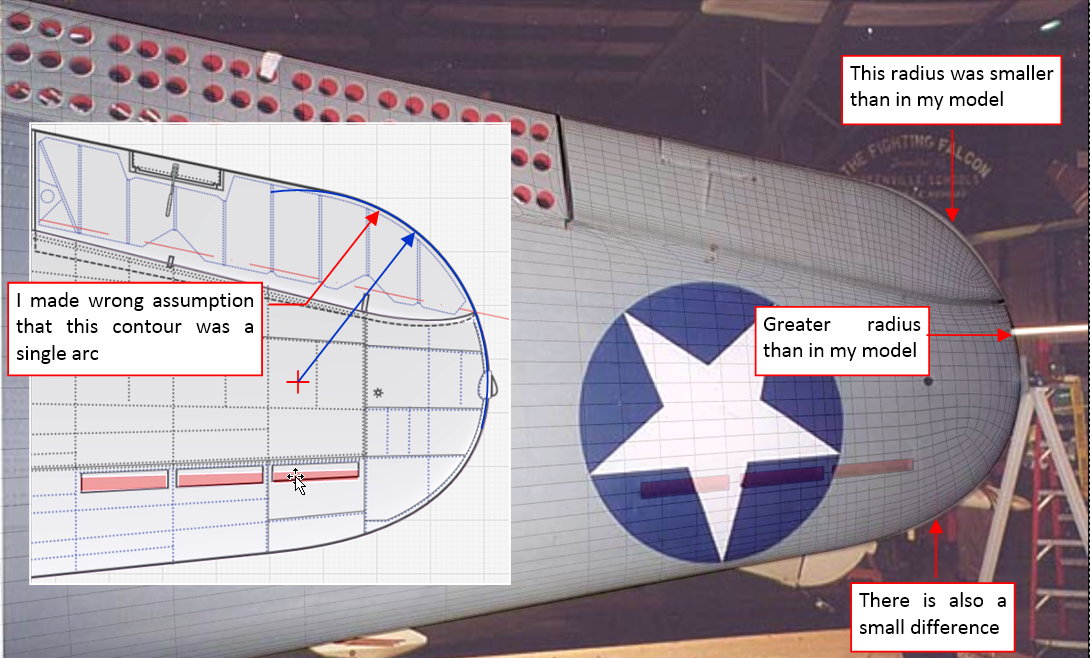
This photo confirms my finding: it seems that I made another wrong assumption about the shape of the wing tip. (I assumed that the rear part was a single arc, while it is at least a smaller arc and an unidentified curve — maybe short piece of another arc of larger radius?). Of course I accordingly modified the wing tip (by adjusting location of a few of its vertices — in fact it was not as complicated as it sounds).
For the complete verification of the wing, I used the picture from the SBD manual. I checked the bottom surfaces of the center wing:
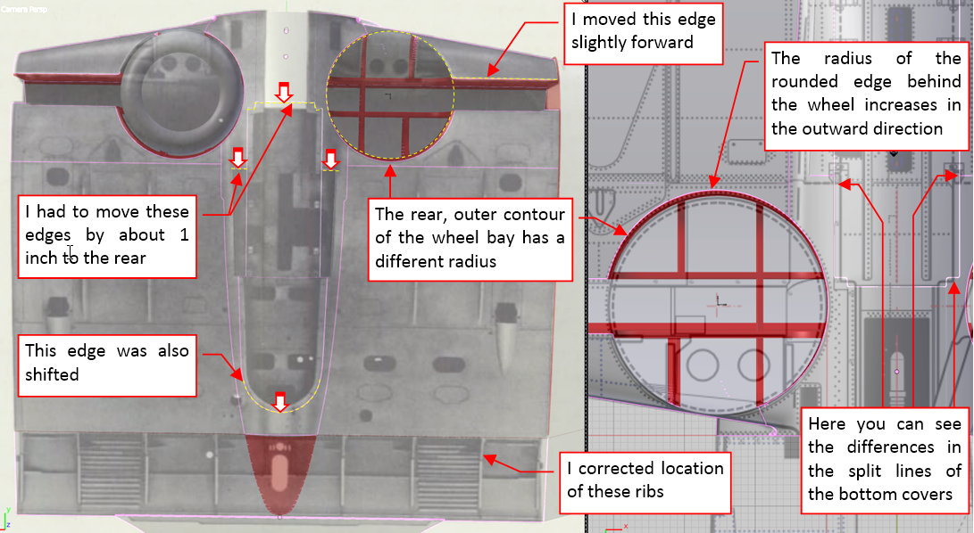
To speed up narration in this post, the picture above is showing the updated mesh. I just enlisted the modifications that I made. As you can see I had to adjust the outer edge of the wheel bay (because it was not a simple circle). There were some minor differences in the split lines of the bottom covers (I had to adjust the bottom fuselage! Again!). Ultimately, I discovered that I placed the fixed ribs above the flaps in wrong locations (I really do not know why I not followed the stations diagram— now I corrected this mistake).
In this source *.blend file you can evaluate yourself the model from this post.
This is the last post about this “great verification”. Now I am coming back to modeling. In next two posts I will recreate the empennage of this aircraft.
Awesome work, as usual. My highest respect!
EDIT: About the wing profile: May it be a twist in the wing? So under the assumption that your previous profile was right, could you correct your finding by just rotating the wingtip along the wing spar axis and adapting your camera match? I know that flying wings have this feature, but not if it was also used on “normal” planes.
Cheers,
Thorsten
Thorsten, thank you!
The NACA-2415 airfoil that I draw on the reference drawing had a flaw. I imported the exact coordinates of this shape into Inkscape, but I forget that all these 2D graphic programs draw the contour line (it always has a certain thickness) around these coordinates : 0.5 of the contour width on each side. Unfortunately I drew this contour using a rather thick line (following the conventions of the classic scale planes). Then I used it as all other modelers’ drawing contours: following their outer contour. Thus the resulting airfoil has thickness of 15.15% instead of 15.00%…
About the eventual wing washout (twisted tips): the SBD design came from the first generation of the low-wing monoplanes (it was modified Northrop BT-1, which in turn was modified Northrop Gamma). Because of this lineage they did not have wing washout (all the sections of their wings had constant incidence angle). In the time of the Northrop Gamma design (beginning of 30’) the problems with the poor stall characteristics of the single tapered wings were not fully recognized. That’s why the Navy had serious problems with the 54 BT-1 dive bombers they ordered in 1936. (They were quickly removed from service because of fatal crashes during landings). Then the designers were ordered to fix this problem. In that time (1938) the wing washout was a know solution of these lateral stability problems that occur at the higher angles of attack (already used in the Spitfire and Japanese dive bomber: Aichi D3A). However, applying such a solution to an airplane that already went into serial production means significant increase of the cost (you have to made new tooling for the wing). Because in that time Northrop went into financial troubles and was sold to Douglas, the new owner did not want such a costly fine-tuning. Instead of this they applied much cheaper solution: fixed slats at the wing tips. They generate higher drag, but do not require changes in the wing ribs and spars geometry. All in all, it had to be an interim model, used in the service for the short time (because in that time Navy already published a spec for the new bomber, which ultimately became the SB2C “Helldiver”). Nobody expected that it will be used until 1944!
Thank you for the explanation!
but why did not you use some free soft to make the basic wing shape NACA 2415
should be more precise then doing it in inkscape !
happy bl
You are asking about reasons of recreating the wing airfoil shape in two steps (the detailed coordinates ->inkscape curve->Blender mesh)?
Well, the “raw coordinates” of the NACA-2415 airfoil contains about 100 points (vertices). It can be even more - but 100 is enough to obtain a “smooth” polygon. I wanted to recreate this curve using much smaller number of the Blender mesh vertices (about a dozen of them per each side of the airfoil). Just to make this mesh “manageable”. It is possible within a certain (small) tolerance, when you are using subdivision curves/surfaces. What’s more, I always place some the mesh vertices along the main longerons/spars. This is a manual process. A convenient way to do it is to draw the precise contour in a 2D drawing (of appropriate resolution), then fit it using Blender mesh (subdivision curves).
I see problem
but could have use the decimate a little may be
or I just made a script to do the NACA 4 and 5 with any number of verts/ segments
let me know if you need it
should be faster and more precise then doing it by hand
happy bl
Thank you very much, it’s very generous.
However, in my “step 1” I already use one of the free NACA airfoil generator. A few of them are available on the Web. Personally, I have used this service since 2007. Now it is a little bit obsolete (required to run a trusted Java application), but I still use it because I prepared a simple pipeline for its output. (An Excel sheet where I paste the results from this web page and obtain the ready-to-use SVG polyline code to paste into Inkscape). As I remember, somebody created an NACA-airfoil generator for Blender (an add-on). However, I prefer to place the wing rib contour on my reference drawing before recreating it in the mesh. (Placing it on the reference drawing helps me in checking the fuselage details around the wing).
as long as references pics have proper X and Y scale then it is fin
but many times I got surprise with difference on Scale X and Y
and on small scale dwg the thickness of lines is a problem to follow smoothly too.
happy bl
Looking good! 
coolfield7: thank a lot! 
In this post I start to work on the tail assembly. The horizontal tailplane has similar structure to the wing — but it is simpler. Thus I started it in the same way as the wing, by forming its root airfoil:
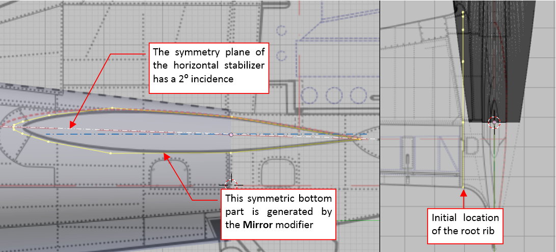
In the most of the aircraft the tailplane has a symmetric airfoil. So it was in the Dauntless. I did not find its signature (family) in any of the reference materials, thus I carefully copied its contour from the photos (its rear part — the elevator — seems to have modified shape, anyway). It has incidence angle of 2⁰, so I rotated the rib object and used a Mirror modifier to generate its bottom part.
During this work I decided that I will use this rib as an auxiliary reference object for shaping the horizontal stabilizer. To precisely match the contour copied from the photos, I rotated part of this curve in the top view. Now it runs along the outer edge of the tailplane fairing:
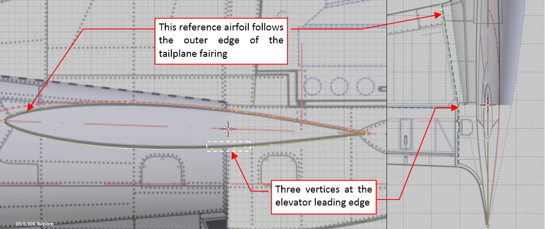
However, because I am going to copy this rib into the initial edge of the horizontal stabilizer, I already prepared three vertices for the leading edge of the elevator (as in the figure above).
During this work I was struck by the idea that it is stupid thing to model the whole empennage, and then to verify it against the photos. The much better approach is first to “draw” in the 3D space their contours and match them to the photos, then to model their surfaces. In this way I can identify errors in my reference drawings before I start the modeling! The parts formed in this “verified” way and continuously matched to the references will have better quality!
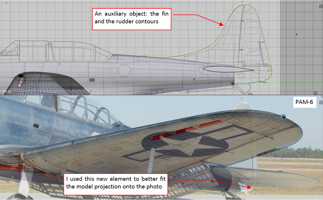
Thus I interrupted forming the horizontal tailplane, and quickly shaped another auxiliary object — the contour of the rudder and fin:
What’s more, I decided to recreate in the model the basic reference “trapezes” of the fin and rudder. They are determined by the explicit dimensions in the general arrangement drawing, which I already used some months ago to draw the 2D reference drawings:
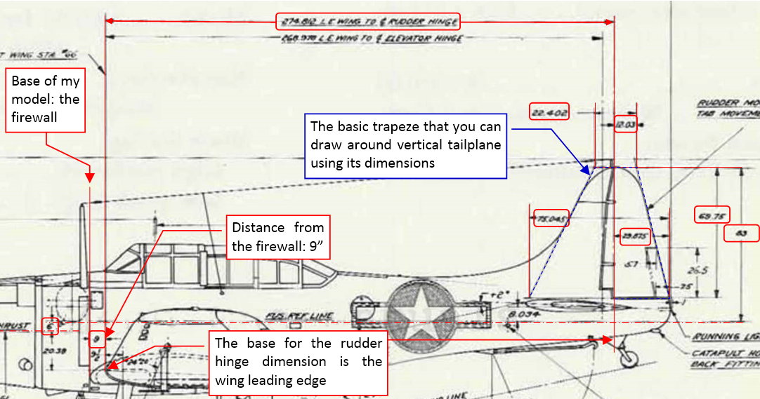
While in the model space the 1 unit corresponds to 1 inch, I did not need to multiply every dimension by the scale coefficient. It was a big surprise when the trapeze drawn according these re-applied dimensions occurred shifted left by 0.7”!:
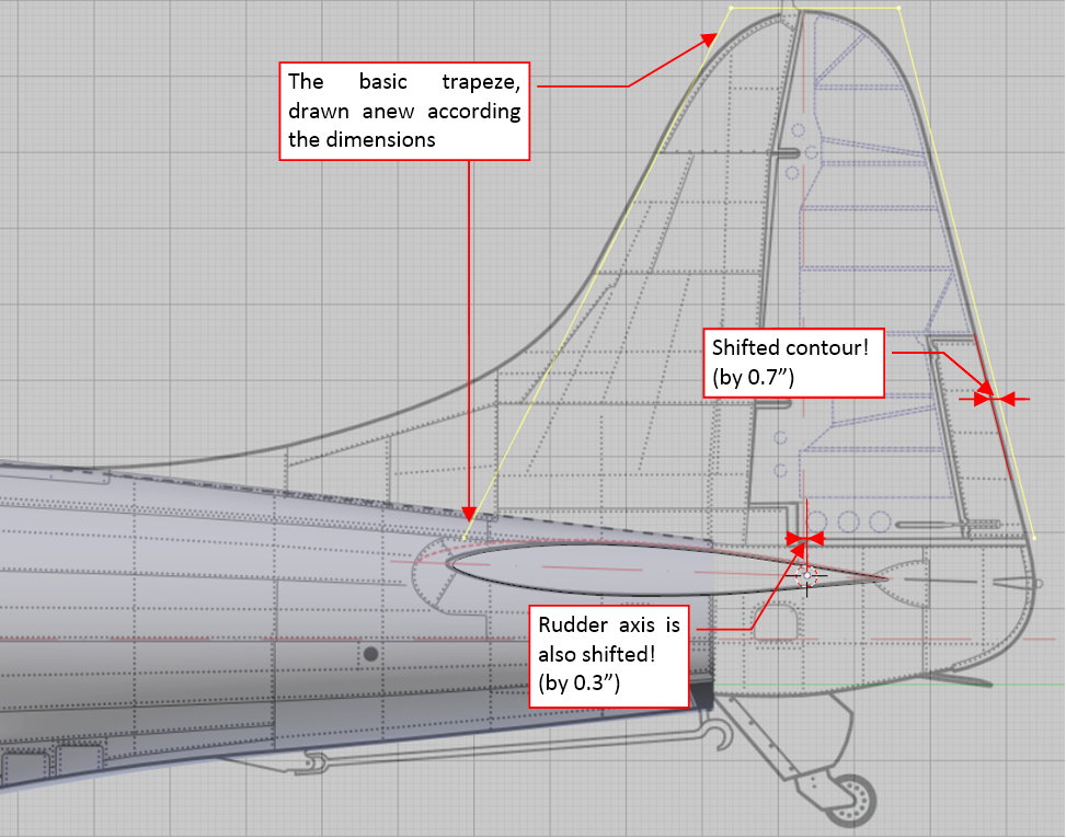
I immediately did the same test for the horizontal tailplane. It also was shifted by 0.7”!:
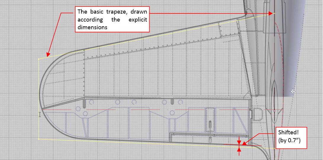
Well, such a coincidence suggest that I made a kind of systematic error in calculating locations of the elevator and rudder axis for my scale plans. Most probably there was something in their extremely long position, measured from the wing leading edge (see the general arrangement diagram in the fourth figure from this post). For example, it could be a rounding error of the scale coefficient!
If I was wrong in this case, I could made other errors. I decided that it is proper time to re-use the original photos from the web page of Chino Planes of Fame Air Museum. Their resolution is only half of the resolution of the photos from Pacific Aviation Museum Pearl Harbor. However, they were made using a long-lens camera. (You can read that the standard length from the EXIF section of the Chino photos — it was 400 mm. The photos from Pacific Aviation Museum Pearl Harbor were made with the standard lens length: 36 mm).
Using this focus length, it is easier to fit the model and the photo:
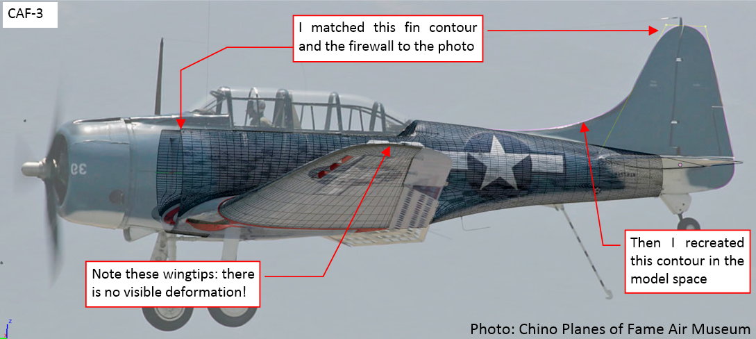
As you can see, this is a flying airplane — and there is no visible dynamic deformation of the wingtip! This means that the whole “theory” about the wing deformation that I described in my post from 5th December was wrong! The wing is much stiffer than I thought. The deformation of the historical photo can have other reason. It could be significant barrel distortion of its lens, or the deformation of the negative. I do not know.
I verified contours of the horizontal tailplane by matching the model to another photo:
Note, that this is another photo that I used to draw my scale plans. However, this time I left it unaltered, to avoid eventual errors that I could made by setting it horizontally and scaling.
In general, the model fits this photo pretty well. However, there are small differences at tailplane and wing tips. I started to suspect that such a photo can still have a small barrel distortion.
Finally, I used the third Chino photo to further verify the side view:
The dimensioned contours of the empennage helped me to match better the other photos. For example, I slightly updated the projection parameters of the SBD-5 pictures from Pacific Aviation Museum Pearl Harbor:
The contours of the tail and fuselage fits the photo pretty well. There is just a visible difference in the wing tip spans — I think that this is the effect of the barrel distortion.
In this source *.blend file you can evaluate yourself the model from this post.
Well, I started to build the tailplane in this post, but this process ended in another verification. However, it spared me from similar check that I would have to perform on the finished empennage. Now I can quickly build this assembly — in the next post I will finish the horizontal tailplane.