Screw threads for 3D printing

First, I’m not sure if this is more appropriate here, in a Blender forum, or in a 3D printing forum, but I know there are others here using Blender for 3D printing and, honestly, this forum has been extremely supportive in many things, so I wanted to start here.

In the attached file I’m including some objects I’ve been using for 3D printing. I left a few objects that aren’t immediately applicable to the question in there, in case they are needed for more detail. The 2 objects to be concerned about are Thread-Male and Thread-Female.

I’ve printed a number of objects with threads, but they’re all ones I’ve downloaded from 3D print sites. I haven’t had to adjust my printer to get any to work. Some fits might have been tight, but, in general, that was good since I knew once the pieces were screwed together, they’d stay that way. I’ve printed thumb bolts and nuts, UNC screws that have fit right into webcam bases, and a few slightly bigger threads. All of that has been pretty much effortless, without having to adjust sizes.

I do want to print some smaller screws, but, for now, it’s a priority to be able to print 4" ventilation ducts to create a vent system for my printing station and, especially, for my CNC system (that also includes a laser for wood burning/cutting). I’m testing on only 2" wide fake pipe sizes for now due to the time and filament 4" pipes.

In this case, I took the male and female thread objects in this file and printed them. Then I printed the male thread part at 99% and 98% size and tried all three. When they were done printing, I could not get any of the male objects to screw into the female threads more than, at most, half a turn, and then, they fight in quite tightly.

One thought I’ve had is that I realized all the threaded objects I’ve printed were double-threads and I’m printing with a single thread. Could that be it?

Another thought was that I noticed that on most screws and bolts the threads all spiraled all the way to the bottom or top of the object, so I’ve done that. (My first efforts didn’t do that.) That hasn’t helped.

I have seen a lot of objects with threads that work, but I want to learn how to do this on my own so I can easily make threads of any length or size that I need for various projects.

ThreadTest-Examples.blend (360.0 KB)
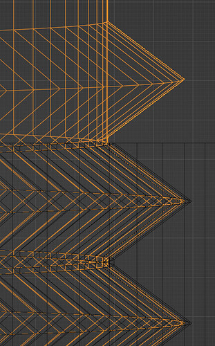
There has to be a small gap between the threads… yes… but not in th Z-axis… if you scale in the z-axis this just doesn’t fit… except with extrem force… but then there is the danger of breaking…

2 Likes

Also…make sure to Apply Scale or you will have problems inside your slicer and you dimensions will not be correct!

So do something like scale down the male on only the X and Y axes?

Can I use the Displace modifier to create a gap? I’ve experimented with that and how it works, but haven’t been able to successfully use it for threads.

That’s one good thing about being able to upload my blend file - I had not realized I had forgotten to apply scale. Thanks!

1 Like

No real need to get into modifiers to do this…Just use S+Shift+z…Scale and press shift + Z
Then it will only scale X&Y… Do it in Wire Frame and judge a good fit… then apply the scale.

Okay. Got that. Let me go over what I was thinking and why I brought that up. For what I’m doing now the more critical size is the male part, since that has to connect to 4" vent pipes. When I try to visualize the entire process, it seems to me it’s a lot easier to scale the male part than the female part - but maybe I’m wrong because I had not been thinking of scaling only on the XY plane. That’s why I was thinking of using a modifier or possibly making a duplicate of the male part and scaling it up a bit, then using that as a boolean modifier for the female part. But now I can see how that’d change the Z scale, too, and create a problem.

So if I use the male as a boolean modifier for the female, THEN scale the female on the XY plane, that should work? (I’ll be experimenting, but since it takes a few hours to print a batch of test pieces, anything I can find that eliminates possible ideas helps.)

As for test prints I mentioned, that’s another reason I’m asking extra questions. I know once I find the right method, I know it’s still going to take multiple tests to verify a good fit (which I know will change from printer to printer and possibly over the life of a printer). I want to make sure I’m doing it right first - so I don’t waste time on a bad method by trying different sizing and fits on that.

One other things:

  • I mentioned single and double threads. Is there any reason to think it makes a difference whether I use single or double?
  • I use the screw modifier on a triangular plane to create the threads. I find I have to have a slight gap between threads or it’s hard to make the thread a manifold. So once I have a manifold thread, and join it to the cylinder with a boolean modifier, I get a mess. You’d think joining two manifold objects would create a manifold object, but it doesn’t. Not with modifiers, so I have to use J to join them. Is there some reason the boolean modifier (using union) has so much trouble joining threads and a cylinder? And, after that, I’m finding it takes a lot of experimenting to get the male cylinder, with its threads, to be used as a boolean modifier for the female cylinder with threads. Even when I make sure normals are point in the right direction and I’ve taken care of duplicates, boolean modifiers just do not like threads.

I can not think of any…shouldn’t make a difference…

So the Male connects to a 4" vent…OK …so I assume you are going to use PVC to connect to it? Or is the Female part the Connector?
So as long as the Male connection fits the connector all should be good…but that also means scaling it in X/Y would change that…and it would be too small…

That does sound like the better option…I would probably go that way myself…are you accounting for the shrinkage on the print…( if PVC)?

I don’t have a 3D printer so I am going to throw this out as an asset that you are free to use or ignore. It is a machine screw (male threads) but does mot include the nut. Most importantly, it follows ISO standards that are described in this wiki article which also describes the spacing required between threads. My goal was to make something that, when printed, would fit in the appropriately sized ISO nut.

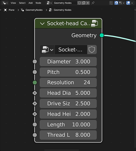
The node interface in the attached asset file looks like this,

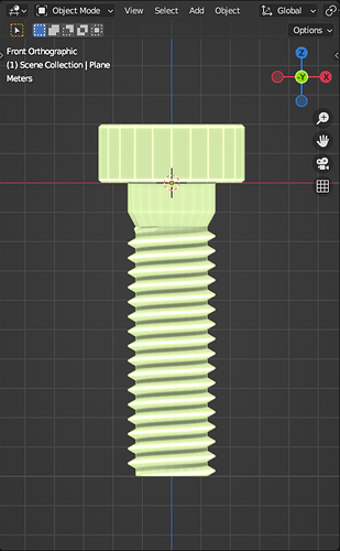
All sizes should be considered millimeters. The default node generates this screw,

This asset file contains a complete hex cap machine bolt. The plan was to make other drive types so caps are separated from threads. If you look at the node group you can use just the thread node group for your purpose. My intent was to eventually do various caps, matching nuts and wood screws.

screwbox-assets-1.0.blend (1.9 MB)

1 Like

I haven’t 3D printed since 2020 but back then I did mess around with threads to print, and my ‘success’ notes were:

BLENDER:
MAKE BOLT XY SMALLER BY 0.95

FUSION 360:
-0.10 MM ‘OFFSET FACE’ TO (3) THREAD OUTSIDES

I hope this helps!

Just to be sure, the 0.95 for the bolt is scaled to 95%, right? (Yeah, obvious, but if I don’t ask, there’s something in there that I didn’t think about or missed!)

Thanks! If I don’t actually use it, at least I can learn from it!

Actually, most of the vent conduit will be flexible 4" conduit, like what you often see used for drier vents (at least in the US). I have multiple issues with this setup. There are a number of issues, like having to pull conduit through small spaces and more. I need to design not only the face plates on the walls, but connectors that will fit with specific angles, and one or two other parts. (I have the designs in my head - I’m just not going to do them all in Blender until I am sure I can make the threads I need.

Exactly! In most cases, from what I’ve seen, people scale the male part down a bit. I have seen and printed some UNC 1/4" mount screws for USB webcams, but that involves only printing a male part anyway and that’s easy to test until it fits. (It means only testing one part for sizing, not two.) I haven’t often seen situations where the size of the male part is critical.

@RSEhlers , After I posted that last comment, I realized I left out another issue and I really should have added another comment, but did the lazy thing and edited that last one instead. I’m finding that the threads I create (I’m using the modifier, not the tool) are manifold objects, but the boolean modifier seems to hate them. I’m finding that most of the time I have to use J to join the thread to the male cylinder otherwise a get a non-manifold mess. Then when I try to form the threads on the female cylinder, I find it hard to get a clean result. I’ve found if I slid the female cylinder up or down some, I get better results at some Z coordinates than others. But it’s like the boolean modifier just can’t handle threads well.

(New idea - I doubt it’ll matter. I’m going to try to use a cube for the female part and if that works with a boolean modifier and the male part, then, after it’s done, I can use another modifier to “cut” the center cylinder out of the cube.)

Yes on only the bolt. S+Shift+Z, then type in 0.95.