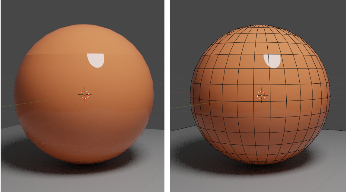
Hi, I’m trying to model a spherical object which appears solid initially, with a domed region that splits open. When I separate the sphere into two parts the EDITlighting/shadingEDIT continuity is messed up at the split line as seen in the attached image. I’ve tried multiple things including:
increased mesh divisions with and without subdivisions → reduces the issue a bit but does not eliminate
duplicate the sphere with a common split line (not separation - the mesh on each is continuous) and setting the sphere material above the split line to transparent shader on one sphere, and transparent under the split line on the other sphere. This sortof works but the renderer has artifacts with the geometry being coincident (z fighting as I learnt in a previous post).
I suspect the issue must be due to the unaveraged normals at the split line, but is there a way to workaround this? Do the vertices have normals that can be locked so they don’t update when the split occurs? I’ve looked online and in the forum, and can’t find any obvious answers to what seems a fairly fundamental issue when modelling anything curvy. sphere _cut_test.blend (743.4 KB)
the continuity is in the lighting/shading not the mesh vertices/edges (I’ve edited the original posting to clarify this). The top of the sphere has discontinuous lighting where it meets the bottom part of the sphere - you can see it in the attached image where the highlight is truncated at the divide. My theory was that it is to do with mesh normals (not that I know much about this in 3D modelling, but from a different engineering application using meshes).
After I posted I found another thread which might be along the lines of what I need to do with normals (see post #18 in that thread), I’m just not sure I understand how to do this yet, or if there is a simpler way to achieve what I want to do. https://blenderartists.org/t/vertex-normal-editor-blender-2-8/1145835
EDIT I figured out how to show normals (Overlays–>Normals) and this is definitely the issue. See attached image.
You can create a new sphere as a source object (or copy whatever you have before the split) and use it for data transfer. This way you can transfer normals without any artifacts. Here’s a file with this setup. Set split normals modifier works too. sphere _cut_test.blend (790.9 KB)
Awesome, thanks for this, this works a treat. A question though, when I show the normals in the overlay settings they still show as two misaligned normals at these vertices, even if I apply the modifier. Is that normal not the same thing?
Also, what is ‘set split modifier’ ?
I was also playing with the Mesh->Normals->point to target, with the target set as the object origin. But it doesn’t seem to work as I expect it to.
I don’t know why it shows two different normals even after applying to modifier. It seems weird to me.
The modifier is called “Normal edit” in the modifier list, but it shows as “Set split normals” when on mesh (also an inconsitency).
Hi, I created a loop cut on the sphere, then edge split and separated by loose parts. This loop cut is linearly interpolated on the edges so no longer following the spherical shape on that face. So the normals are the same anyway at both sides of the split and doesn’t have this problem. I’m assuming this is not what you mean? Thanks, Pete.
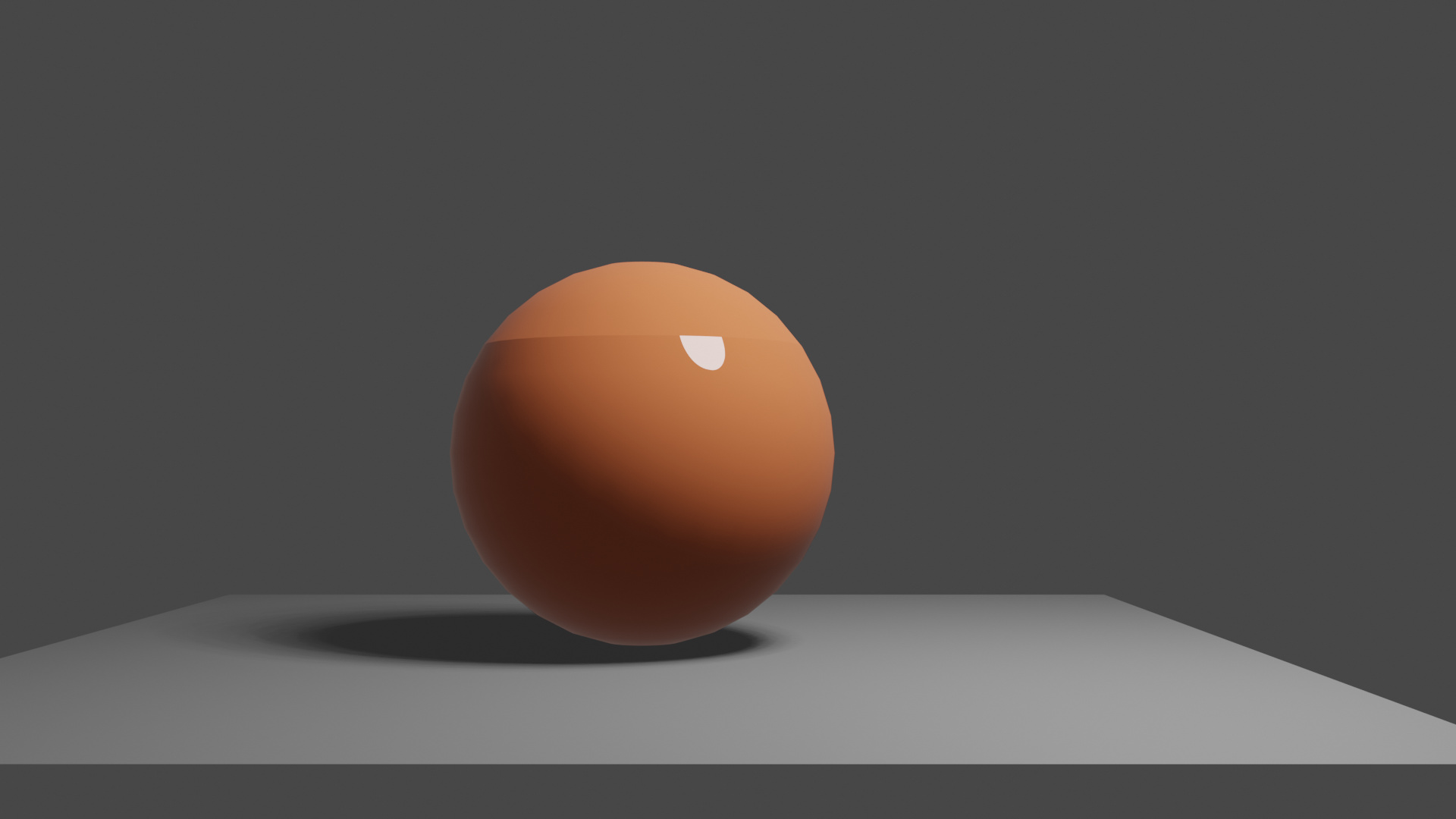
Hi, I tried changing the lamp to a spotlight with the original blend file and it still has the issue (see attached image)? Did you have to change some setting with the light to stop the shading discontinuity?
Thanks, Pete.
Hi, this issue is easier to see with a low poly cylinder (see image).
Starting off with an 8 sided cylinder (‘O’ in the image), this has an edge split on the top left face (in A1 and B1). However in A1 you can see that the face is flat, so the split line is in the middle of a flat face. Whereas for the geometry to represent a cylinder it needs to be like B1 where I moved the vertices out to roughly lie on the real cylinder radius. You can then see the difference when you split ‘V’ at that new edge between A2 and B2. Because the split is in the middle of a flat face in A2 the normals at either side of the split are the same, whereas in B2 the faces are curved (not parallel) and the normals have changed to be normal to the faces either side of the split. Caveat - I may be over simplifying or plain wrong with my understanding of what is happening here, this is just my observations from playing with it. Pete.cylinder_normals.blend (568.1 KB)
Hi John, this is what Cdog suggested earlier in I think post #4, and works a treat to sort the problem. But I’m also interested in how to manually edit the normals, because as you start modifying the mesh away from its initial primitive shape, this no longer works. Cdog also suggested you can use the data transfer option to copy from an arbitrary mesh, which is more convenient, but still requires you to have a copy of the mesh prior to every split (and if you don’t notice a problem, or forget to do this) then its still a pain to fix unless you rejoin and resplit.
There is also some weirdness going on where the normals are showing split after fixing, even though they appear not to be from the sorted shading.
I have tried playing with the mesh->normals tools but they don’t seem to work as I expect them to (am still playing around with them - and if/when I figure it out I will post on here). Thanks, Pete.
Yes, that must be the reason, can be verified with loopcut → to sphere and the shading is bad again. So it is not a bug, so more a precision problem. The recalculation of normals in such situations is unwanted cause they are already good. So an “edgesplit, keep normals” is needed.
So more an ask for an feature on rightclickselct!?