Tools for curves

One more thing about integratability, see here: http://en.wikipedia.org/wiki/Differential_geometry_of_curves#Length_and_natural_parametrization

It seems that you were right, Mackraken. Apparently, if you want to calculate an analytic function for the curve length, you need to integrate the magnitude of the derivative of the curve. For cubic bezier curves, this means (if my calculations are correct) you have to integrate the square root of a 4th order polynomial. That probably isn’t going to happen, unfortunately.

I thought about expanding the function to integrate as a Taylor/Maclaurin series (with any given number of terms), but even that seems daunting, because of the repeated application of the chain rule (separating the square root function from the polynomial). But maybe that’s just because my calculus is a bit rusty… :eyebrowlift:

I was thinking about it and it seems that the answer might by rather simple.

The function calct in my script parametrizes the whole curve, thats why the precision parameter must be so high in order to get an aproximate result. With a bad decimal precision, and summing 1000 or more times the results, the error increases.

Instead splitting the whole curve, you can try “splitting by segment”, maybe 4, 5 or even up to 10 splits by segment should be enough to get much better results.

If the error amount comes from summing truncated floats results along that high precision number, this may be a way to minimize that effect.

I cant try this by myself right now, but if you do please let me know.

curveToolsLengthDecimalBEZIER.zip (2.5 KB)

Hi,

I’ve updated the code (see attachment) to use Decimals instead of floats, which should in theory allow for as high a precision as one would like (default is 24, which should be more than enough). I started out by just ‘decimalising’ the curve parameter, but that didn’t really work out that well, so I decided to decimalise the whole thing.

In order to test the accuracy of the calculation, we need some curves whose lengths can be analytically calculated (to any desired precision). I’ve been testing this on 2 such curves (both with 1 segment): a straight line and a parabola. Here are the control points (in the xy-plane; from left to right; with x in [0 to 3]):

  1. line: (0, 0), (1, 0), (2, 0), (3, 0)
  2. parabola: (0, 0), (1, 0), (2, 3), (3, 9)
    The length of the line is obviously 3, and the length of the parabola is (possibly a bit less obviously) about 9.747. You can call the static method CalcLengthParabola39() to get this length to any given precision. Also note that these control points really do result in a 1st and 2nd degree polynomial, respectively, and not in some ‘degenerate’ case of a 3rd degree polynomial.

Of course, these control points are vectors which are input through the GUI, and whose components are probably floats. If these are ‘floats’ in the pure python sense, I think they should actually be doubles (in the C sense), and should (at least in my case, on a 64-bit system) give a resolution of 128 bits, which would give an accuracy of about 33 decimal digits (http://en.wikipedia.org/wiki/Quadruple-precision_floating-point_format). Somebody please correct me if this is wrong. This seems worth mentioning, since we probably can’t do better than the resolution of our inputs.

Now it gets a bit weird. As can be seen from the control points above, our test curves are both defined by (small) integer coordinates (0, 1, 2, 3 and 9). One would assume these have an exact representation when they are converted into floats. This indeed seems to be the case; there are some global functions in the script that allow you to check this (near the bottom; TestPrecisionIntegerFloats*()). One might therefore think that, for these specific curves, since the inputs have an infinite precision, one could derive the length of the curve to any desired precision. That, however, is apparently not true.

The DecimalCubicBezierCurve class contains some logging capabilities. Especially the inputs are interesting (method LogBezierControlPoints()). For the line, everything works as expected. For the parabola, however, we immediately drop to an accuracy of about 7 decimal places for some of the coordinates (1 and 2), even though those coordinates have the same precision (whatever it may be) and are input in the same way (through the GUI). I really don’t understand what is going on there. Btw, please note that I’ve left out the world transformations for now, in order to narrow it down.

Anyway, for good measure, I should probably mention that I already have a good enough accuracy for my intended purposes. So it’s not that I expect to have a decimal precision of 24 digits always and everywhere, because that usually doesn’t make any sense. So you might want to look at this as a rather theoretical exercise. Actually, what worried me in the beginning of this pursuit, was that, by increasing the precision/nrSamples parameter, you could get a much more inaccurate result. I wasn’t quite expecting that, certainly not for the (rather small) precision range I was interested in.

g_crv_bezier_01.zip (3.56 KB)

Update, see attachment.

The code has been refactored into some more classes, like DecimalCubicBezierSegment, DecimalCubicBezierCurve and DecimalCubicBezierCurveIntersector. So we’re still on cubic bezier curves only. The length calculation remains available, of course.

I’ve also added a first attempt (brute force) at calculating the intersecting point(s) of 2 (selected) curves. To use: select 2 (intersecting) bezier curves, copy the multiline comment starting at line 259 (in g_crv_bezier.py) and paste that into the blender python console. That should print out the intersection points and put an empty into the scene at these points. It uses the spline.resolution_u parameters as the number of samples, so you probably don’t want to make these too big.

Still to do regarding these intersections:

  1. make it truely 3D (you may get false intersection points if not everything is in the same plane)
  2. insert control point(s) at the intersection(s) (in both curves) (without changing the geometry of the curves)
  3. add a blender bezier curve to the scene from a (theoretical) DecimalCubicBezierCurve (so we can check/execute point 2)

Still to do generally:

  1. clean up the code
  2. possibly implement a non-uniform curve parameter (based on length of segments)
  3. and probably some other stuff… :slight_smile:

g_crv_bezier_02.zip (4.42 KB)

Another update. You can now intersect 2 selected (non-cyclic-bezier-) curves. It adds an extra control point (in both curves) at the intersection(s) of the curves. Btw, this implies that we can now add any (theoretic/generated) DecimalCubicBezierCurve to the scene, which is nice.

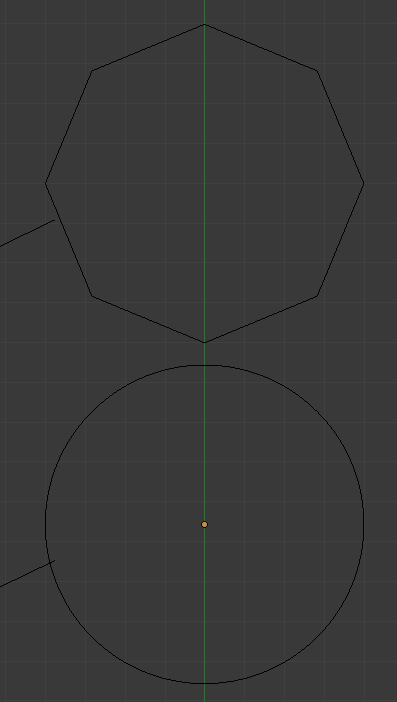
I’m still nowhere near to where I’d like to be, however. So let me elaborate a little on what I would actually like to achieve (see screenshot below). I’m trying to model a castle. It consists of some walls and some towers, laid out on a septagon (regular 7-sided polygon). I’m trying to lay out its ground plan using some circles and lines. It would be nice if it were possible to combine (parts of) these curves into a single curve, which could then be used as a guidance for a curve modifier. Here’s an illustration:


So I would like to be able to get from those 5 curves (1 for the tower exterior, and 2 x 2 for the interior and exterior of both walls) to the 2 interesting (single-spline) curves in blue and yellow.

This implies intersecting the curves (done), removing some segments of the resulting curves (which seems to result in several splines in the curve data, which is annoying) and joining the remaining parts of the curves – preferably as 1 single spline curve.

Hmm… :rolleyes:

Looks good lateur

Ive an algorithm which intersects curves given an orthographic or perspective point of view. the point of view is important since seeing those curves in your picture from the front side you cannot get any result since they are in the same plane and intersects in an infinity of points.

The algorithm is expensive and not exact but can achieve decent results:

Bezier curves in blender has a U Resolution parameter, which is the amount of straight lines needed to represent a bezier segment of 4 control points.

You can use the parametric cubic equation to get a U amount of lines for each segment, for example, for a bezier segment with 4 control points and a U resolution=4 u can get the first line by calculating the cubic equation for t=[0, 1/4], the second t=[1/4, 2/4] and so on.

This reduces the problem to a simple find a cut or cross between lines belonging to the 2 intersecting curves. This is:

Given 2 lines (which are portions of each curve), you can create a plane between the first line and the point of view. If this plane intersects the second line, u gotta check if the intersection point is outside the line itself by using the line parametric form, if the parameter for that point isnt between [0, 1] is not and intersection point between lines neither curves.

So by comparing lines belonging to the two curves, you can get the intersections “or crosses” between them given a point of view.

Optionally and to solve performance and accuracy u can discard many operations by calculating the crosses with a low curve resolution to check what areas of the curve are more likely to intersect and increase the resolution on those areas. I havent tested this part but could work very well.

Nice to see this useful addon under development.
Keep it up guys!

@Mackraken: my current implementation actually works like the procedure as you outlined it, but without the dependance on the point of view. I’m only interested in the points where the curves really do intersect, regardless of how you look at them. As mentioned above, there’s still a little work to be done to actually get this to work on 3D curves, but that shouldn’t pose too much of a problem. It will probably involve defining some ‘nearness’ limit, though, so we can establish whether or not a point actually lies on a line segment – and also, whether or not 2 (distinct) points can be considered the ‘same point’. But that’s something I’ll propbably have to implement anyway if I want to get the functionality as described earlier.

I also considered starting out with a ‘rough approximation’ (small resolution) of the curves to find some possible intersection candidates, whose intersection point could then be refined recursively. This does imply the risk of missing some intersection points, though, as illustrated below:


We could consider some kind of bounding box algorithm to exclude some segments from the detailed calculations, but that doesn’t seem to be that obvious – at least not in the full-blown 3D case.

@Carrozza: thanks for the support! Don’t get your hopes up too high, though, as I’m just trying to recuperate/update some of Mackrakens original code… :smiley:

Thats right lateur, nice example, even in that case you can implement an algorithm that studies the curves before looking for intersections since finiding them is expensive on high resolution curves with many control points, (U=12 or more). With low resolutions everything is cheap, so even if the intersection point lies outside the line, we can use the distance to sort what segments should be processed first. Then, find intersections for those segments on high resolution and if there isnt any stop, since the other segments are “less likely” to intersect. This should be the way to go in order to optimize operation, the method implemented inmy script was “brute force”, finding intersections with high resolution curves.

The point of view for intersections is a powerful tool for modeling since the curves doesnt need to be “planar” or in the same plane. You can project both curves into the “point of view plane” and find intersections there, then project them back to the curve. This was implemented in maya 3 and 4 back in the 90s and is more versatile since you can perform this operation for your example or any other even if they dont intersect in real 3d space.

For example your castle, you can use curves at the towers to perform cuts on the ones at the ground, using the orthographic top view.

Finally, if you need me to explain my code to you please let me know, we can set an skype conference and ill gladly help you to go on with your code.

Thanks for the skype offer, Mackraken, I might take you up on that! But not just yet. :slight_smile:

I see what you mean about the point-of-view-plane intersection thing. That’s quite powerfull indeed, modeling-wise, and probably a little faster, too, since the intersection operations are 2D. It’s also, as you rightly say, perfectly applicable to my castle project – and probably to a lot of ‘architectural’ modeling. Btw, Maya 4 was the first ‘real’ 3D tool I ever used. Outrageously unstable, though, I seem to recall…

About optimising the intersection operation: it may indeed be a good idea to order the segments according to the ‘probablity’ of an intersection occurring. However, I still have a nagging little feeling that, in some cases, this may result in some false positives and/or negatives. Unless I’m missing something, I think you can’t be 100 % sure you’ve got everything right unless you apply the brute force (full resolution) operation. And even then…

Still, in many cases (like the castle case), it might really speed things up. If you assume you know the number of intersections points there are (N), you could refine the most probable candidates and stop if you’ve found (and accurately resolved) N of them.

I should probably look into supporting splines, though, before trying to optimise anything else. That’s the next part of your code I will be going through – and may have questions about…

Ok, I’ve been thinking about this, and maybe it’s time to take a step back and try to focus on the ‘bigger’ picture for a moment.

As you may have noticed by now, I’m quite willing to put some effort into getting some of Mackrakens functionality working again. Looking at the lifetime of this thread (over 4 years and counting), surely we all agree that blender currently does not (yet) support this (yet obviously desired) functionality. I assume the developers are aware of this, too. It would be nice to know where they stand on this. Is it:
a) Updating curve modeling/functionality is not on our todo list.
b) Of course this is on our todo list, but we don’t seem to get around to it. It’s at the bottom of the list; it’s just not a popular request.
c) Hold on a little longer, the upcoming 2.7 branch will fulfill all your curve modeling wishes.

Responses to the answers above may include, in reverse order:
c) Maybe we should hold our breath for a little while and see what happens.
b) It may be worth the effort of trying to update/maintain this code. In this case, it would help if we had an idea about whether this (updated) code is likely to break any time soon (and/or often, in short/middle time terms).
a) It might not be worth the effort, as the chances of ‘breakage’ (cost of maintenance) may be quite high in this case. Heck, they may eventually even fade out curve support altogether, for all I know.

And while we’re still in ‘global view’, let me repeat that I’m not primarily into this to develop curveTools-v2 – although I’d like to see that happen as much as the next person, of course. I’m mostly into this for the castle mentioned above. You could say I’m getting to know my way around the mathematical curve/surface stuff (the original code obviously helps a lot), but I have almost no experience in developing an actual (public) addon (+ GUI). The fact that I can’t get the original addon to work, doesn’t really help there, either. So if this is going to evolve into a curveTools-v2 addon, then I’m definitely going to need some help in those areas.

I’m well aware that this sounds like I’m getting cold feet. And, to be honest, I probably am, a little. My python programming skills are quite rusty (to say the least), I’m only just starting to get a grip on the blender API, and I’m used to WPF (well, what can I say) for all things GUI. Actually, if it weren’t for my (hopefully sufficiently solid) grasp on the mathematics behind it, I’d probably be the worst candidate for the job. But somebody has to do it, because otherwise my castle will never get finished… :wink:

Anyway, back to the splines, now!
g

Hehe, nice arguments.

This addon was born to put in practice the few math skills i have, it was quite fun to see that they were finally useful.

The biggests issues this addon has, is the bmesh release. This, was developed before the new mesh creation and I guess that fixing only that part will make this to work again. Ive seen a few changes on drivers (i might be wrong) that may need some work, but the thing is that the calculations dont need any update in order to work, just optimization perhaps.

This addon has loft, birail and some minor curve utilities like change nurbs weights and intersections or crosses. Im not sure but if script modifier works by now, the drivers trick can be replaced by this.

I can walkthrough you through the addon development, gui and python which are the easiests parts of this or any other addon. The math logic is slightly harder to code, for me.

To develop any addon i dont use any IDE but Blender text editor and some utilities ive created like the Class Viewer addon, i can instantly check functions, the blender console is also useful to test and check variables.

curveTools2.zip (2.71 KB)

I’ve updated the code to work as an addon, see attachment. It only has the Calc Length button for now, but it’s a start.

I’ve eliminated the DecimalVector thing because its use seems to be mainly theoretical. Also, it’s quite hard to do this thoroughly. Eg, every time the user edits the curve interactively, you fall back to the built-in float accuracy. So it doesn’t really seem that useful to keep it in. It still uses decimal precision for the curve parameter, though, but even that may get kicked out eventually. Also note that it uses local coordinates (for now), so make sure you apply your scale first.

A question about using bpy.props (eg FloatProperty): is it still the recommended practice to store these properties on the Scene type? Because it would appear that this may cause some name clashes with other addons when used lightly. Eg, I can imagine some other addon needing a ‘length’ property. I’ll adhere to the convention of starting all the property names with ‘CT2’, for now. It would be nice if these properties could be kept in a custom made object, like CT2Properties, but that didn’t seem to work for me.

Another question about (Float)Property: does anybody know how to make these readonly? Is it possible at all? Because I saw that bpy.types.Property has a is_readonly property, but I can’t seem to set it.

And finally, it appears that you can have curves containing splines of different types (eg, bezier and nurbs). This raises some interesting questions if we eventually want to ‘merge’ the adjacent splines of the curves. Btw, nurbs curves are still not supported at all.

Still, it’s better than nothing, isn’t it? :smiley:

It is best practice to create a namespace to store the properties to prevent collisions. You can do that by creating a PropertyGroup, define the properties there, and then create a PointerProperty with that PorpertyGroup. You will be able to access them like bpy.context.scene.curvetools.myproperty

The best way to improve precision is by writing a better algorithm than the one i wrote. It can be improved in so many ways. I guess Decimal Precision would help but rewriting the script would work better.

curveTools2-001.zip (3.34 KB)

I’ve attached an updated version of the code.

@ Mackraken: thanks for the namespace/PropertyGroup/PointerProperty info; it works like a charm! I hear what you’re saying about accuracy/performance/optimisation, but I propose we come back to that later, so we can focus on getting some (crudely/brute-forcely implemented) functionality going, for now.

@ batFINGER: Unless I’m missing something, your suggestion doesn’t seem applicable to this (updated) code, as there is no ‘self’ available while defining the FloatProperty (in init.py). What we’re looking for is a non-interactively-editable (Float)Property GUI-thingy – which may only be available in certain given contexts.

curveTools2-20131201.zip (10.1 KB)

(Small) Update!
Finally, though… :slight_smile:

Mainly been working on the intersection of (2 selected) (bezier) curves. Here’s how it looks:


A note on the curve intersection operation properties, from bottom to top (easiest to hardest):

  1. Affect
    You can choose which of the (2) selected curves the operation has an effect on. Options are ‘Both’, ‘Active’ and ‘Other’. May be usefull if you have a ‘cutting curve’ (Other) that you want to (repeatedly) apply on some (Active) curves.

  2. Mode
    Defines what happens at the intersection points. Can be ‘Empty’ (very easy and visible – nice for debugging), ‘Insert’ (add segment to spline) or ‘Split’ (split spline into 2 splines).

  3. Algorithm
    ‘3D’ or ‘From View’. The last one is usefull if you want to intersect curves ‘as seen in the (first) view3D’ – see an earlier post from Mackraken about this. There still are some problems with this setting. It only works as excepted if you are looking through a camera (numpad 0), or if you’re looking from a (built-in-user-camera) ‘ORTHO’ ‘RegionView3D’. I may need some help on solving this ‘PERSP’ ‘RegionView3D’ issue…

  4. LimitDistance
    A property I didn’t think would have been necessary for this functionality – until recently, that is. At least, it isn’t needed when in ‘Empty’ mode. Anyway, we will probably get into this deeper, eventually.

  5. To test/use:
    – a. create a standard bezier circle (radius = 1)
    – b. change the resolution (‘Preview U’) to 256
    – c. duplicate it and move it so that it still intersects the original
    – d. check/set the aforementioned operation properties and push the button!

If it doesn’t work as expected:

  1. try increasing the resolution of your curves (and thus waiting longer for your results)
  2. try adjusting the LimitDistance:
    – making it smaller may result in too many intersections
    – making it bigger may result in too few intersections
  3. check the system console – there may be some warnings/tips there.

Any feedback much appreciated!

curveTools2-20131208.zip (12.7 KB)

Ok, time for another update, see code in attachment. Mainly been working on joining neighbouring splines. Here’s how it looks:


The interface is getting a little cluttered, I’m afraid, but it will do for now. I’ve subdivided it up into three sections/boxes, depending on the number of curves you have selected (1, 2 or 1-or-more).

Some extra curve info functionality has been added, so you can get more detailed information on your curve. Some of this info will only appear in the system console.

In the 1-or-more-curves section you will find some convenience functions, eg to set the resolution of all splines of all selected curves to a given value. There’s also a button to remove splines without segments, which seem to appear sometimes when you delete some unwanted segments in the (intersected) splines. (I think this has to do with blender not realizing you’re deleting the first/last segment of a spline, and still generating 2 splines unstead of removing the first/last segment of the active spline). There’s also a button to remove all splines shorter than a given threshold, which may be convenient in some cases.

The final button lets you join all neighbouring/adjacent splines within a curve. There’s a distance threshold you can set that determines when 2 points will be considered to be identical. You can choose to respect the directions of the splines by checking the ‘only start & end’ checkbox. If this isn’t checked, some splines may be reversed in order to join them together. And finally, there’s a join mode that sets how the join will be performed: by moving both control points to the midpoint of them, or by inserting an extra segment between those control points.

So there, I’ve finally reached my initial goal of generating a single-spline curve of my castle walls by intersecting and joining various constituting curves. Hurray! :slight_smile:

curveTools2-20131211.zip (14.3 KB)

Updated code in attachment.

Most interesting addition: loft operator. So you can select 2 (bezier) curves and create a b/mesh from them by joining each corresponding pair of points by a line. That could look like this (using 2 standard bezier curves):


Unfortunately, there’s no ‘driven’ option yet, as I have no idea on how to implement that. I guess you’d need to be able to catch some events from a ‘driving’ curve/spline to be able to update the generated mesh. This has been touched before, but maybe someone (possibly you, Mackraken :)) could elaborate on this a little? Also, what is this script modifier? There doesn’t seem to be a lot of information about this, at first sight.

Still, the loft operation is a good proof that we can generate b/meshes in the scene. This may open the way to support swept and/or birailed surface generating tools.

Also added: a button to set the origin of the curve to the starting point of the first spline – handy when using the curve modifier.

A castle-based example of this curve modifier:


I wanted to upload a screenshot to illustrate how this castle thing could look like when rendered, but it doesn’t seem possible to upload more than 3 attachments at a time. We can get back to that, if necessary.

Hi, which Blender version are you testing it on? Pressing the Loft button outputs errors in 2.68a.

I’m also using 2.68a (r58537), on 64bit win7 pro.

Make sure you have 2 bezier (!) curves selected.
What errors do you get?