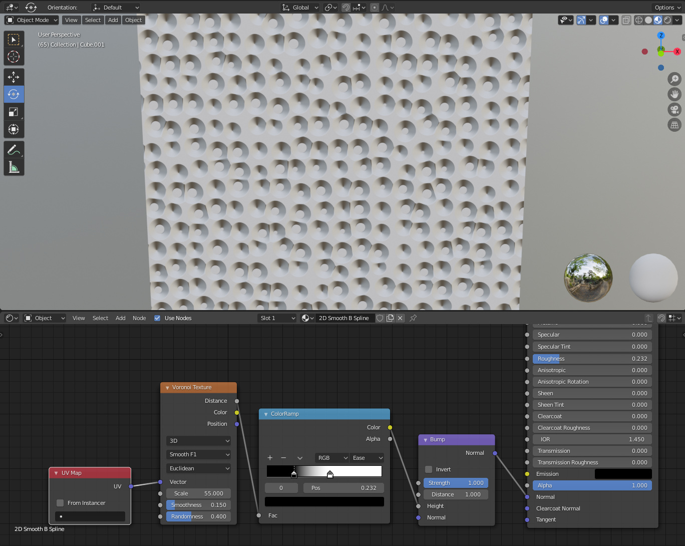
I’ll eventually want to add coloration as well, but right now I’m stuck on the actual hammer marks. I started with a voronoi, which seemed like a good enough start as far as placement, but the cells have a kind of pointed/cone-shaped look, as opposed to the soft, round divots that the hammer actually creates. This is what I have so far:
Bringing the white down using the color ramp does a pretty good job of adding some space between the hammer marks. I was hoping that bringing the black up would smooth out the bottom of the cells as well, but as you can see below, it kind of just chops the bottoms off. Not quite what I’m going for.
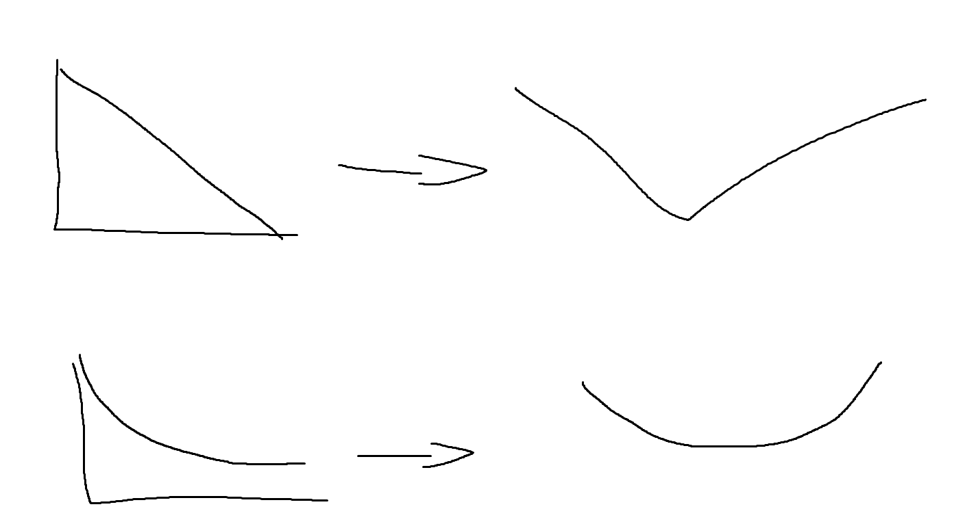
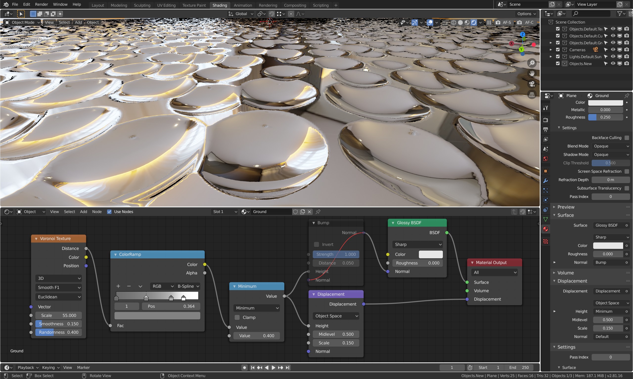
As Acrivec says, it’s “just” a matter of manipulating the curve. However, if you preview the Distance output, you’ll notice that it never goes to black, and each depth is slightly different. So you’ll need to increase the black level of the ramp and I also get better results using B-Spline. For manipulating the shape, I recommend temporarily using adaptive displacement.
It’s not going to give you a perfect result, as the depth varies for each cell, but I think it’s close enough. Here I’m using a math/minimum to clip the top after the ramp.
This is perfect @CarlG, thanks! I have one question though- what to you mean by “temporarily” using adaptive displacement? Would it be a problem to keep this node tree intact and keep building upon it?
Also, this is my first time posting on any kind of forum and I have a protocol question-
I have a few other things I need to figure out with this particular texture. Is it okay to keep this thread running with additional questions until the “final product” is achieved, or is it better to start a new thread for each individual question?
Thanks @Acrivec! Your illustration makes sense graphically, but I’m not sure how I would actually implement it in Blender. It looks like CarlG’s expanded on your answer. Is this what you meant?
I mean that using adaptive displacement makes it easier to judge the resulting curve while adjusting it using ramp and math nodes. If you preview only the color going into bump height, it will be subject to color management making it really hard to “see”. Even when turning off color management it can be hard.
Even so, switching to using bump doesn’t always produce the expected result, and I have no idea why my gradients doesn’t produce the bump bevels they are supposed to. For bump, use strength 1 and adjust the distance to physical scale - I often use a value and a divide by big number for very small distances.
I have little experience with cycles nodes, however I have realized that procedural textures and color ramp nodes need to be counter-gamma-corrected for a their B/W use in masks, bump and displacement; to do so you have to link them to a Gamma node set to 0.454545 , (that is 1/2.2).
I hope it can help.
Ehm, sorry to correct you (please do not take it badly), but no, that isn’t the case.
As you mentioned, though, I did some test out of curiosity, and there actually seems something unexpected going on, when feeding the color output into a scalar input. I couldn’t figure out, what transform actually is used.
Some findings:
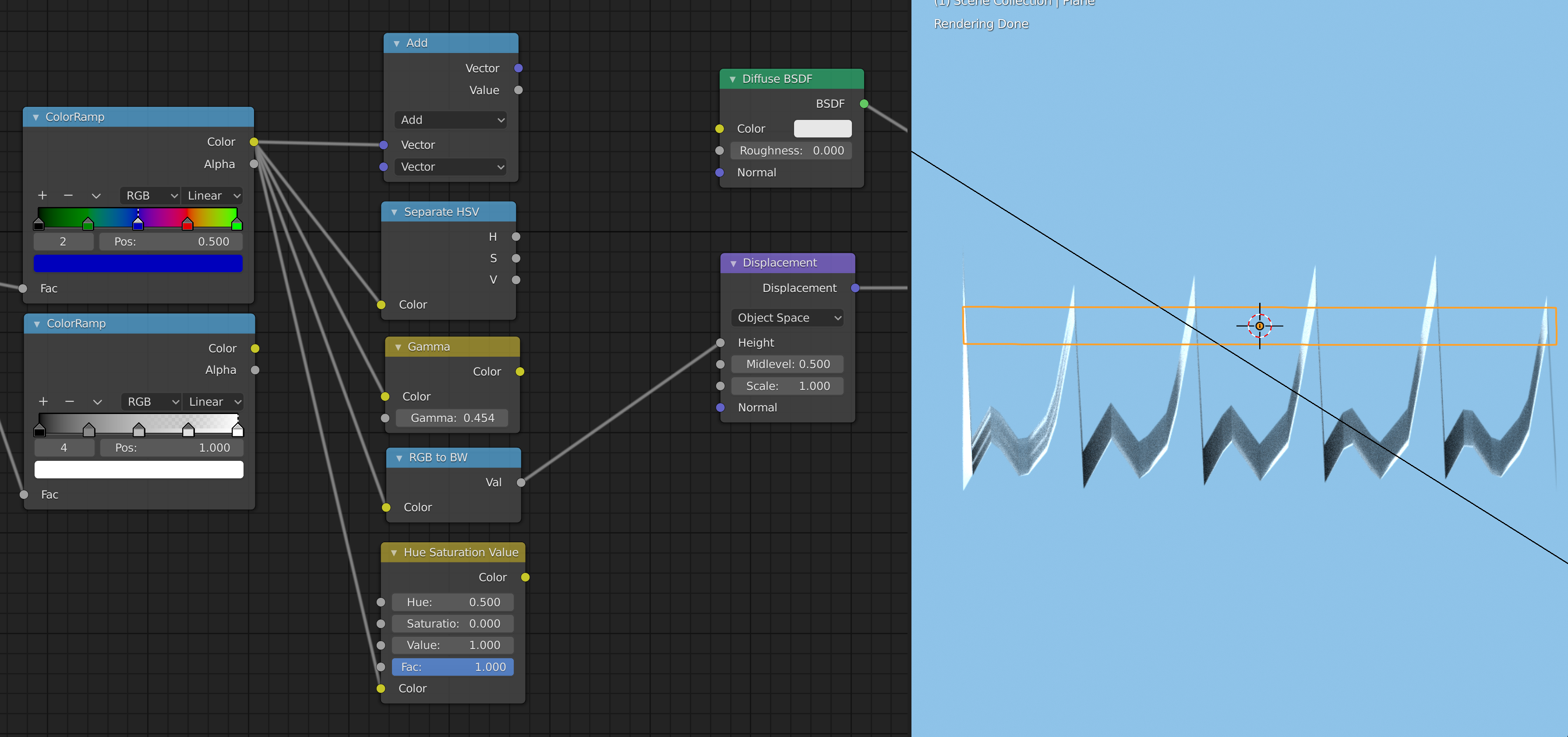
if you only use greyscale on the color ramp, the conversion will just be the RGB value (which is the same on all channels)
if you use different colors, the output is neither:
– the average of the RGB components
– the V of the conversion to HSV
– the result is the same as if passing the color through a RGB to BW node
– if one sets the interpolation mode of the color ramp from RGB to HSV, the V values of the HSV transform behaves linear
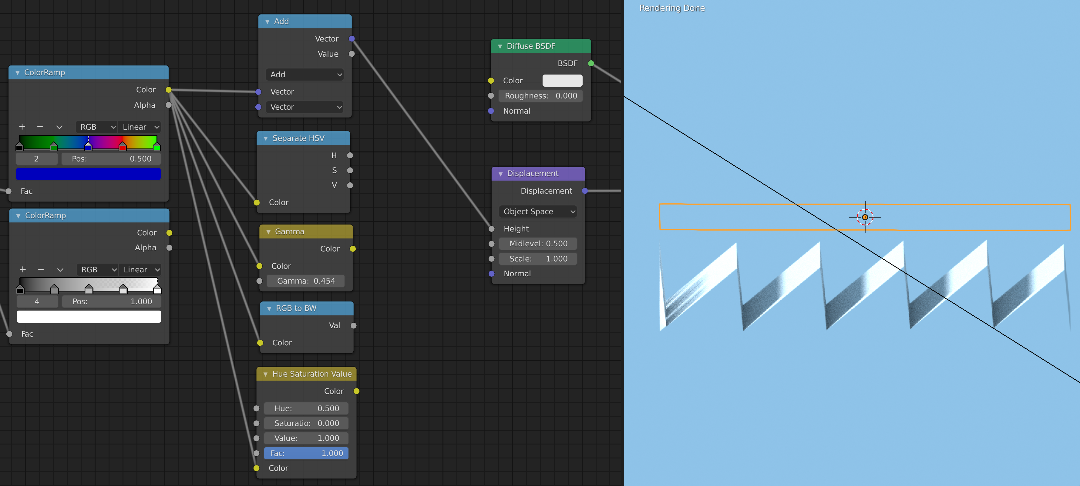
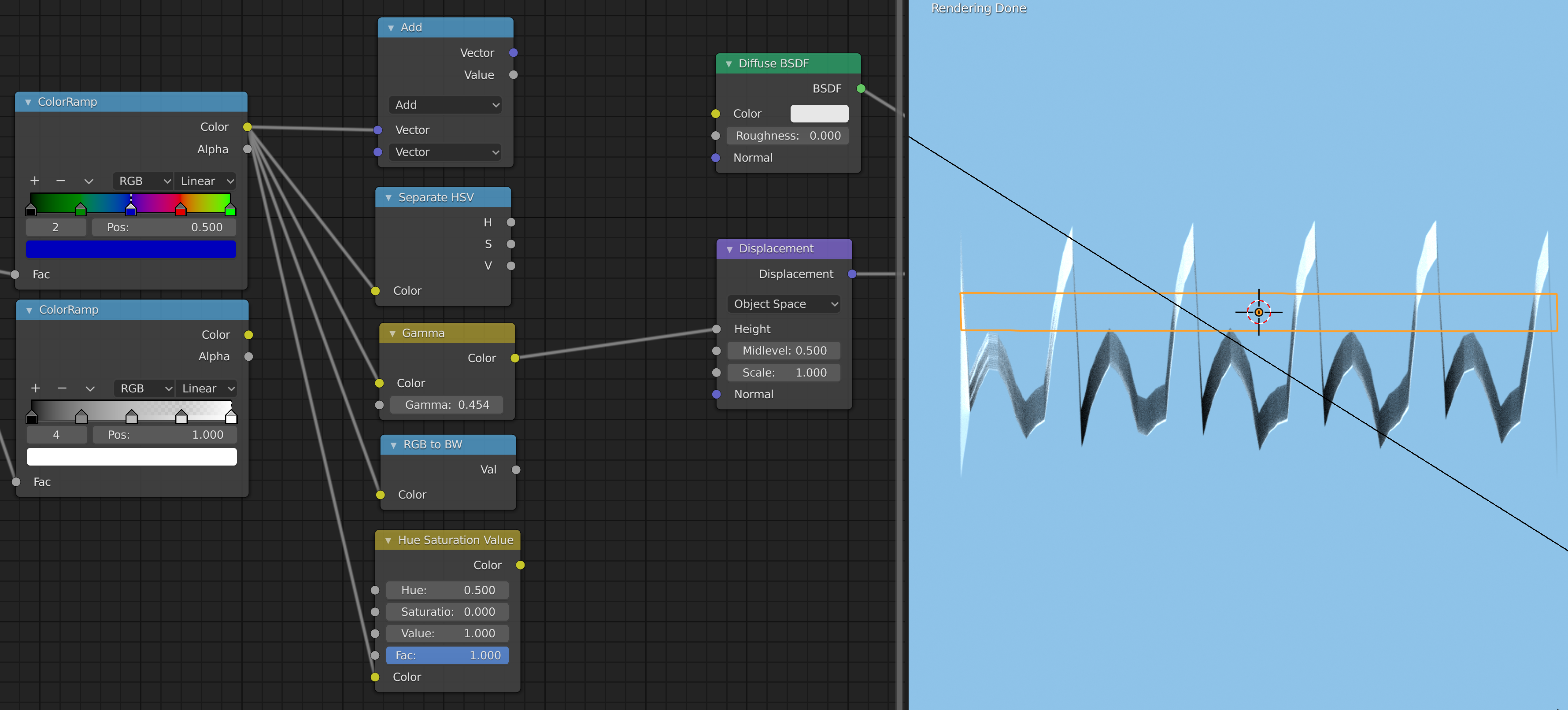
Here are some screenshots. I feed a sawtooth pattern into the color ramp and passed the output (after conversion) into (true) displacement.
No problem at all @omgold, as I told my experience with cycles is quite limited, and I pointed out just what I have empirically observed.
I have made the assumption that to generate bump or displacement only B/W input was used, I have no idea of what happens when RGB input are involved.
What I observed is that if the output of non-color data is passed through a B/W color ramp node, it needs to be corrected in order to get a 0.5 grey to produce a 0.5 middle level, in other words an output of value 0.5 in RSV actually result as 0.73 (EDIT: ‘errata corrige’ 0.217) if not corrected.
Sadly I don’t use 2.8 so I’m not able to proficually play with your file, In my previous tests of 2.8x all values were messed up.
Ricky,
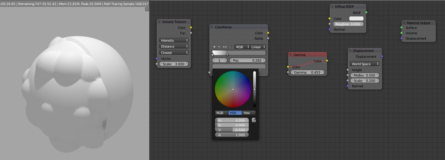
I have made an object with 2 materials applied, one is a simple diffuse, the other is the same with a displacement.
The displacement is generated by a Voronoi texture passing through a Color Ramp.
Since the Mid-level of the displace node is 0.5, a 0.5 grey should not displace the mesh at all, but that’s not the case unless I correct the Color Ramp output by a Gamma node.
You can see in the images the difference when I disable the Gamma node: the surface where the displacement input is 0.5 grey doesn’t match the half surface without the displacement.
Ah, okay, now I get what you mean. That is not an issue of the color ramp, but of the conversion between HSV and RGB. The value you see on the displacement node apparently is the RGB value, but you set HSV to 0.5. Switch the color picker to RGB then you see it.
But looking at that closer also, things get confusing again. The transform used by Blender obviously doesn’t match the standard definition of HSV, which should produce for greyscale V=R=G=B:
But then the gamma correction of 2.2 doesn’t match also, although it comes close. There doesn’t seem to be a constant gamma matching precisely for the full range:
Since long time I have given up with understanding Blender color correction that IMHO is a big mess, but for a correct result in bump or displacement necessarily I had to do something.
I found out that for simple B/W input the counter-gamma correction works, but now you make me understand that when I’ll have to use an RGB channel to this purpose things will be more difficult.
The purpose of linear color correction is to make the colors in the rendered image to visually match those chosen by the user, am I right?
So what sense does it has that , for example, I should assign a pale gray to get a medium gray?
I should be able to choose a color, maybe a Pantone® XXXX and get a matching result, otherwise what’s the use?
Don’t worry, you don’t have to answer this question.
color management is a mess and still buggy
needs a lot of TLC
one thing I remember is that if you want exact color for an image
get it from the UV editor using color picker
taking if from viewport won’t work because of color management
Yes, that’s right, but if you sample a color from an image in the UV editor and paste it in a RGB node you’ll get a totally different result, because of color correction.
What if you literally hand-painted a bitmap with some randomly hand-placed “splotches” using some [other …] paint-program and then used that as a displacement source? (You could UV-map overlapping areas from a comparatively small map.) That would give you "true pseudo-randomness" which might help believability. To my way of thinking, any “mathematical” technique is going to just feel too regular.
Not more difficult when used for non-color stuff. It seems when you set the RGB values to the output value you want, you will get that value directly, without any correction necessary.
About render, I believe when one sets color management to sRGB/standard and gamma=1 (the correction factor in the color management tab), the colors in all views and nodes should be consistent.