UPDATE: I have merged this metal shader with my thin film interference shader. Please see this post for all included materials and some possibilities: https://blenderartists.org/forum/showthread.php?403299-UPDATE-Cycles-PBR-thin-film-interference-and-metals
Hey all,
After all the recent flood of PBR tutorials, I thought I’d try my hand at making a metal shader that would
- render the correct color
- render the correct Fresnel behavior
all based on the complex refractive index n+i*k. Essentially all color and Fresnel information is contained into these two numbers for a given wavelength. For many materials the n,k values can be found at the well-known refractiveindex.info web site, so this shader might be an alternative for rendering realistic metals and semiconductors.
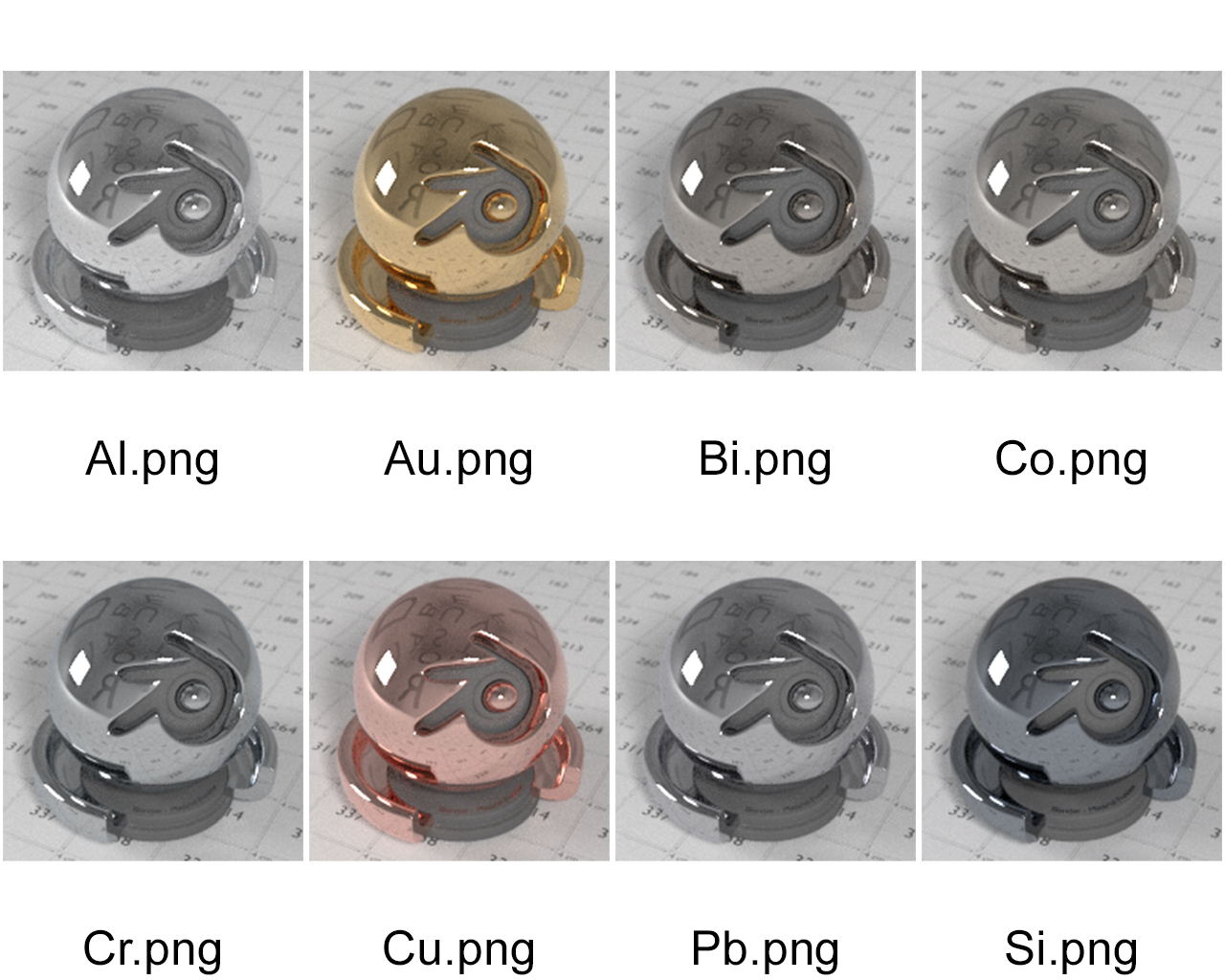
I was planning to make a node group from scratch, but I had a look at Blender’s source code tree and I found an OSL function called fresnel_conductor, which triggered my curiosity. Not so long story short: what I wanted to make was already there in OSL (but it should be easy to recreate the OSL shader with ordinary nodes). I’ve taken the n,k values for red, green and blue* and plugged those into an OSL script for various metals. The results are shown in the image below. Note that I never defined a color anywhere, it’s all just the fresnel equations at work**. Also, when zoomed in onto the edges, a color gradient is visible (especially for the tinted metals), which seems to indicate that it works as expected. I also provide the .blend file with the OSL script link removed, outdated!
If anyone wants to re-implement this in plain Blender nodes, the contents of the fresnel_conductor equation are (source https://git.blender.org/gitweb/gitweb.cgi/cycles.git/blob_plain/refs/heads/master:/src/kernel/shaders/node_fresnel.h):
color fresnel_conductor(float cosi, color eta, color k)
{
    color cosi2 = color(cosi * cosi);
    color one = color(1, 1, 1);
    color tmp_f = eta * eta + k * k;
    color tmp = tmp_f * cosi2;
    color Rparl2 = (tmp - (2.0 * eta * cosi) + one) /
                   (tmp + (2.0 * eta * cosi) + one);
    color Rperp2 = (tmp_f - (2.0 * eta * cosi) + cosi2) /
                   (tmp_f + (2.0 * eta * cosi) + cosi2);
    return (Rparl2 + Rperp2) * 0.5;
}
I hacked in the lesser influence of the Fresnel effect with increasing roughness, as I have no clue what it should be to be accurate. Right now, at a roughness of 0.0 I take the physically correct Fresnel behavior. At a roughness of 1.0, I take the Fresnel value of 45° and apply it everywhere, regardless the angle of incidence of the light. The reasoning behind this is that we might see some kind of angular average (big question mark). For roughness values in between, I interpolate between these two extreme cases.
Edit: It seems that to implement Fresnel with rough surfaces properly you need to have access to the microfacet distributions of normals. Cycles / OSL doesn’t provide for this, so a physically correct implementation isn’t possible without implementing a microfacet surface shader first. The upcoming patch by Lukas Stockner mentioned below will take care of this by implementing a new surface shader type, with surface roughness weighted by the Fresnel coefficient.
Here’s the OSL code:
#include "stdosl.h"
#include "node_fresnel.h"

shader node_fresnel(
    color n = color(0.2),
    color k = color(3),
    normal Normal = N,
    float roughness = 0,
    output color Fac = color(0.0))
{
    float cosi = dot(I, Normal);
    Fac = fresnel_conductor(cosi, n, k);
      color Fac2 = fresnel_conductor(0.707, n, k);
    Fac = (1-roughness)*Fac+roughness*Fac2;
}
Finally, I didn’t check the render speed compared to other solutions like for example using RGB curves (found here: https://blenderartists.org/forum/showthread.php?361151-Cycles-Materials-RGB-Curves-and-PBR-rendering-UPDATED) Interpolating over the angle might be faster than doing the angle-dependent calculation over and over. On the other hand, with this solution there is no interpolation over the angle, and it’s less work to set up a new material (fill in 6 values). Anyway, I hope it’s useful to someone.
*I took the n,k values at the wavelength of 650 nm ®, 532 nm (G) and 450 nm (B). I think it would be best to do a spectral average of the primary colors of blender, but I have no idea what wavelengths these correspond to.
** I didn’t check the correctness of the equations