i tried to UV map the side of a boat with view unwrap
which does a 90 degrees projection but that’s not good
cause you loose the 3D effect of the model
and it does not look good at all !
so which method is best so you keep the 3D effect of the mapped object ?
you mean just do a simple unwrap
not a view projection unwrap !
ok i’ll do a test later this week and be back
thanks for helping
hope this work fine
but first i got to do my map hope this can be done in blender
how can you do your own map in blender if possible
i mean do you have to unwrap then paint it ?
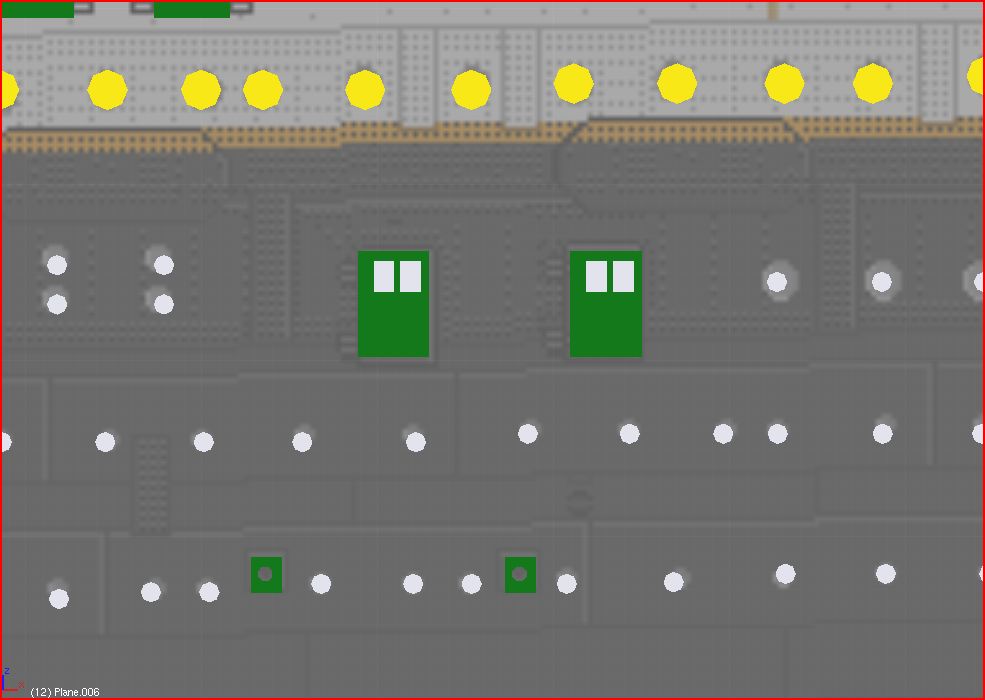
i mean i’v already made most of the light and doors on the boat side as a 2D image in blender
but how can i use it for the UV Mapping onto the boat side on 3D model ?
i mean i don’t really wont to paint manually 200 lights plus all the door
just repeat it in blender and save it !
might be abnle to make an alpha map for the plates on teh side
but not certain this can be done !
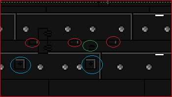
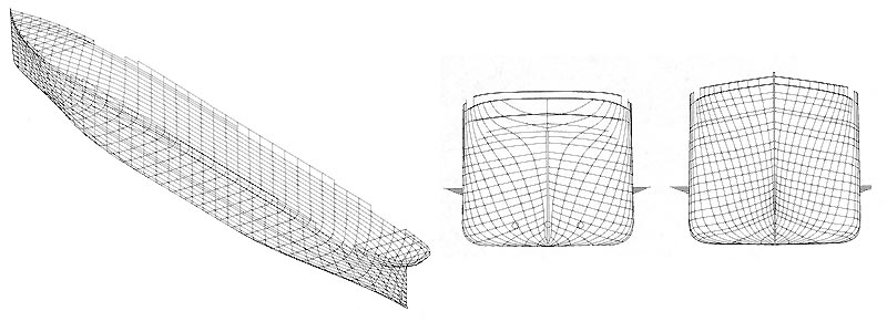
No, firstly go into side ortho view then select “project from view” type unwrap.
then pin the top three quarters like ive done in the bottom of the first image (the red dots are the pinned verts) then on the model (in the 3d viewport) select the bottom verts & do a normal unwrap.
that way when you export the uv map out to texture in photoshop you can do the portholes in a straight line, the bottom bit doesnt matter as much cos its only really red & out of view.
I`ll be around next week to explain more if thats still confusing.
well i did that on another boat last year and it was a real disaster
the side of the boat look totaly flat cause the mapping was flat like planks horizontal
i don’t wont to see this again
mind you 3/4 of the lenght is flat vertical so not really a problem
but for the 2 ends where they are rounded inward then it will do something
but not certain it will come out nicely !
now for the map can it be done in blender or not ?
i mean i can try to do it in GIMP but find it very difficult
cause i need some windows rounded i also got some doors and other details i want to add on the side
that’s a lot and it’s very long
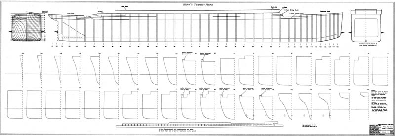
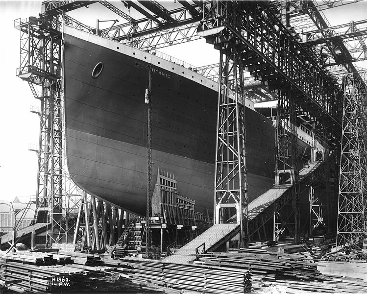
i mean i’m doing titanic ship with 100’s of windlow holes on the side ect…
and i want to do it in cycles with a good realist look
so how to make the mapping easy if possible in blender
i could use baking
making a high res model for holes and doors ect then baking it and using this as a UV map
e window dont’ need to be included in this UV map!
i will add circles mesh with some emit in cycles so that these act as a light source for the water around in the ocean!
and only needto get the doors and plating on hull i guess
rivets not necessary too small on thsi model
unless i do a very close shot on a specific location!
For some reason it wont let me add attachments anymore, just wont upload. I`ll send a pm about references.
doing it in blender would be making your life more difficult than it needs to be, as I dont think it has the needed image editing tools.
for example to draw a line you would draw a path in photoshop then convert path to stroke to get a smooth line.
you could possibly do that in gimp but not in blender i dont think.
I aint made a titanic yet, its on my list of things to do.
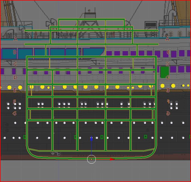
Thats funny, I was working on doing a cross section probably from the same image & run into a few errors.
if its the same cross section reference were both using then that reference was made as a promotional image before the titanic was constructed, so its not accurate in terms of how things line up.
well the cross section shown in green is for the beams structure
not the boat decks
so wondering if i should use that one to determine the general height?
and another thing i saw is that some side pictures seems to show that the decks are not horizontal from left to right
like near the back or front some decks seems to change elevation like having a slope
so not certain anymore i think i have to modify my decks inside to follow these slope!
but this does not change the overall shape of the hull only the inside!
so for now not a major problem
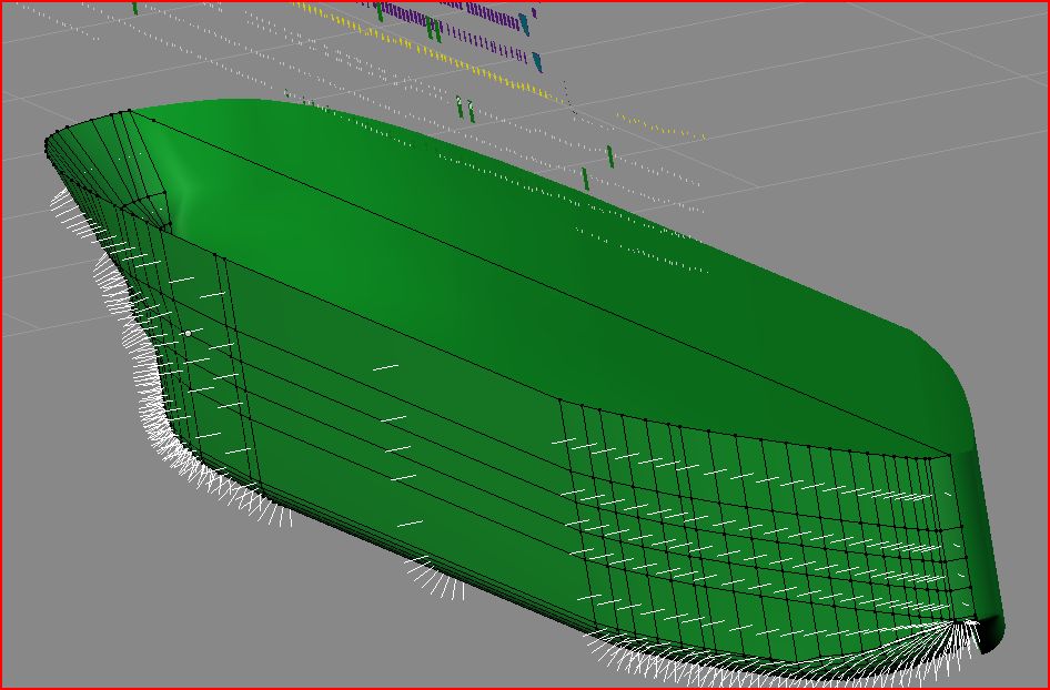
first i have to make my plates image for the side
but for unwrapping it will probably be in 3 parts
one for the vertical side
one for the back rounded may be more then one unwrap !
one for the front rounded
nmay ahve to apply 3 materials here to get 3 clean UV map!
let me complete my hull and i’ll do a test on UV unwrapping later on
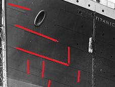
Titnaic hull plating boggles my mind. I did have a diagram but I cant find it so i drw it from memory.
vertically its like this.
whilst horizontally its like this.
the top line (red dot) is how it the diagram was, no welding just rivets. however I cant figure out how to make it work logically so id just consider it like second line (green dot) that works easier


