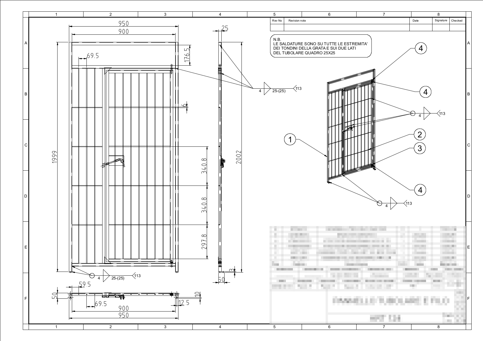
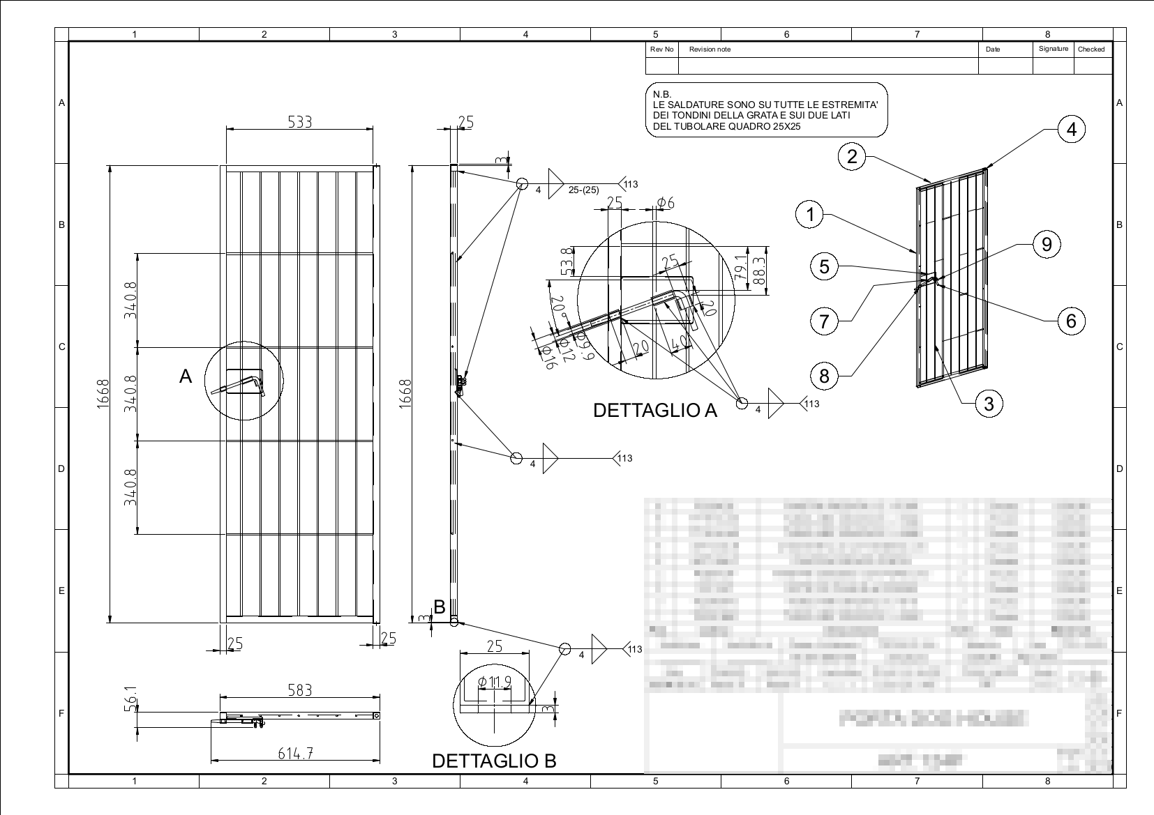
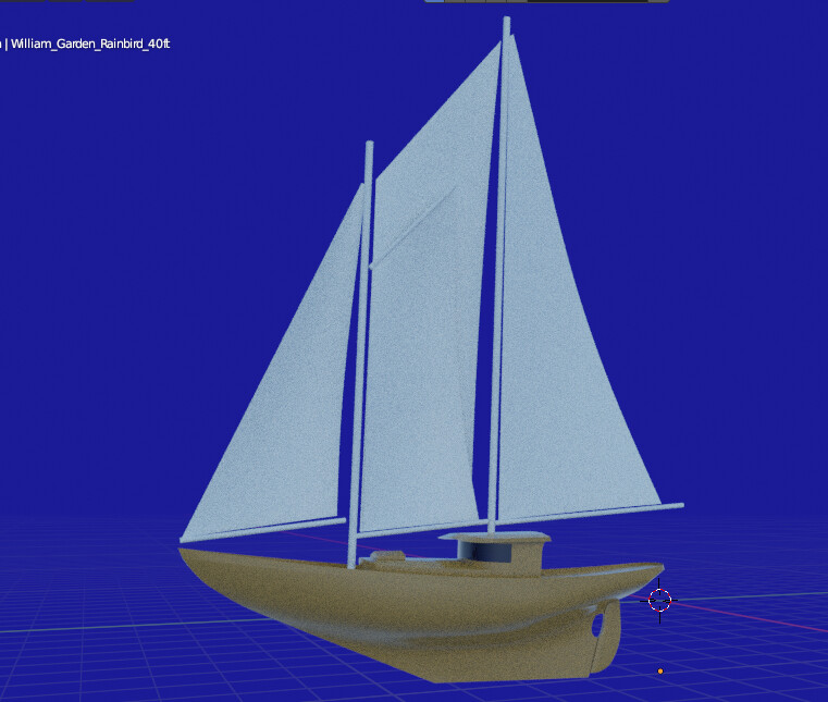
Hi this is one of the last results that I have obtained with Blender a workflow that I have been carrying out for some years and with the latest version and collections things have become much simpler, I also have other projects but which are currently in the process development and I can’t share, for privacy reasons. But as soon as they are completed I will share them.
I don’t want to deceive anyone by declaring that Blender can replace normal CAD programs but for me it is now possible to generate complete 2D draft in Blender.
I have waited for years for some news on the NURBS implementations but as it is now known, everything has been stopped for some time. I just hope that with the latest developments there may be some new mind that improves this part.
Thanks, I’m glad it can be useful. here are some tips.
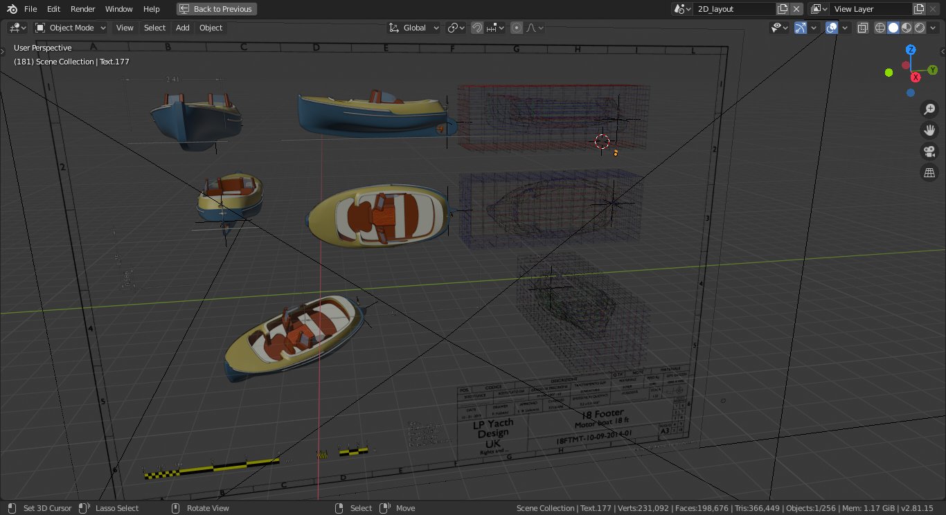
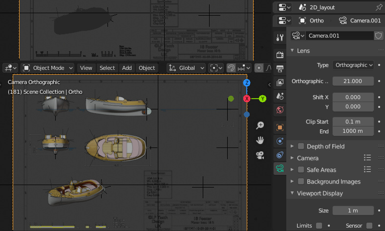
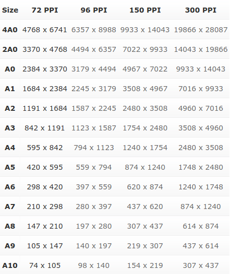
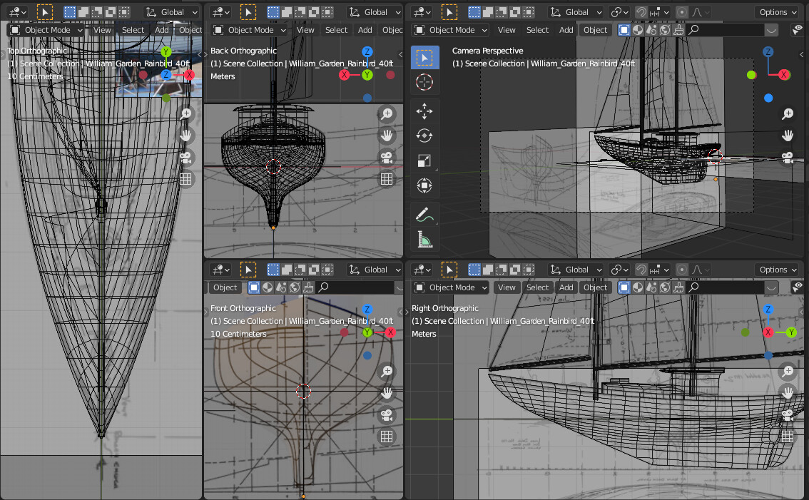
To have a good resolution, I set the print values so as to obtain a rendering at 300dpi, and I scaled the A3 template of the sheet 50 times, keeping the models in 1: 1 scale and then I enlarged the scale of the camera orthogonal to 21.000, set the value on the longest side, which can be measured with the addon measure it.
And last advice, I made a new scene where I added a linked instances objects of every things in the new scene thus having the possibility of modifying objects on a normal scale, in order to edit everything in other scenes, where I have the block of the squaring and the block text. In the final layout are all instances, taken from the file, where I basically have three scenes, one for the project, one for the text blocks and more. The only thing to do, you have to enter the dimensions in the final layout, but you can keep the rest as an instance.
Some image of the settings.
You can simply type your measurement in imperial unit * 300 dpi.in the image resolution field.
Or in metrics.
21cm /2.54 *300
So you do not need this table anymore
Interesting. What’s the end goal for this application?
I’m an industrial designer and I work in software like Solidworks, Catia, Inventor and AutoCAD. I use blender for creative purposes and advocate pushing it towards technical applications. Which it is not really designed for, but shows some potential. Stuff like this seems like good small steps in the right direction.
Also keep in mind that in the engineering world, depending on your field, you’re going to encounter different drawing standards. Sometimes dictated by a client, by the scope of work, other times by internal standards, other times by international or professionally agreed on standards.
Plus things start to change depending on disciplines. For example, civil engineering and mechanical engineering are both engineering fields, but each will have completely different standards, including producing drawings for many reasons. And even within one field, you can have varying standards. For example, producing shop drawings for fabrication is different than producing overall assembly drawings (such as a boat). Even within the same project.
Unless it’s for graphic design, You will never hear things like “how many pixels.” It’s usually more “I need the drawing in ANSI E size” or “just print it 11x17 (ansi b size drawing) for me to review at my desk”. Often we even produce architectural scale drawings (ARCH) or ANSI scale drawings (ANSI) for the same client.
So those CAD programs are design to be versatile. When I do work for architecture firms vs doing work for utilies Engineering, I’m constantly switching back and forth from those standards.
I only say that to help focus your purpose. Looks good
Sorry I saw this only now, I know the standards and this thing is problem with Blender, this idea was come out in mind because I need a way to produce draft with Blender, I used many CAD program in my life like Rhinoceros Solid Edge and Solid-works, for work, but now I’m passionate in boat design. and that gave me the possibility to make drawings printable in real scale from the rendering layout, and I also had success in exporting to DXF many production design from Blender. Now I’m waiting the LineArt features for that purposes I think this can give more possibilities.
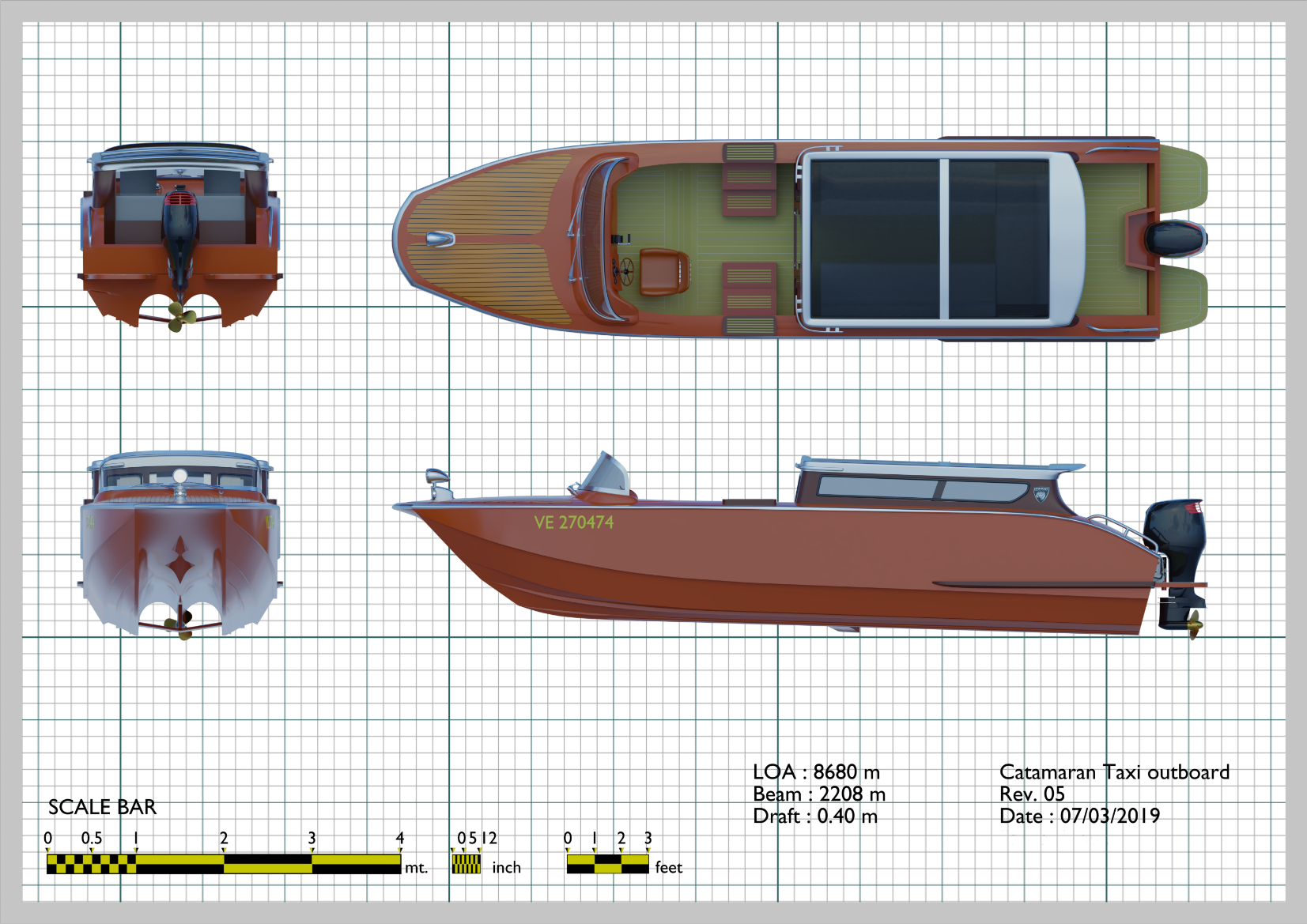
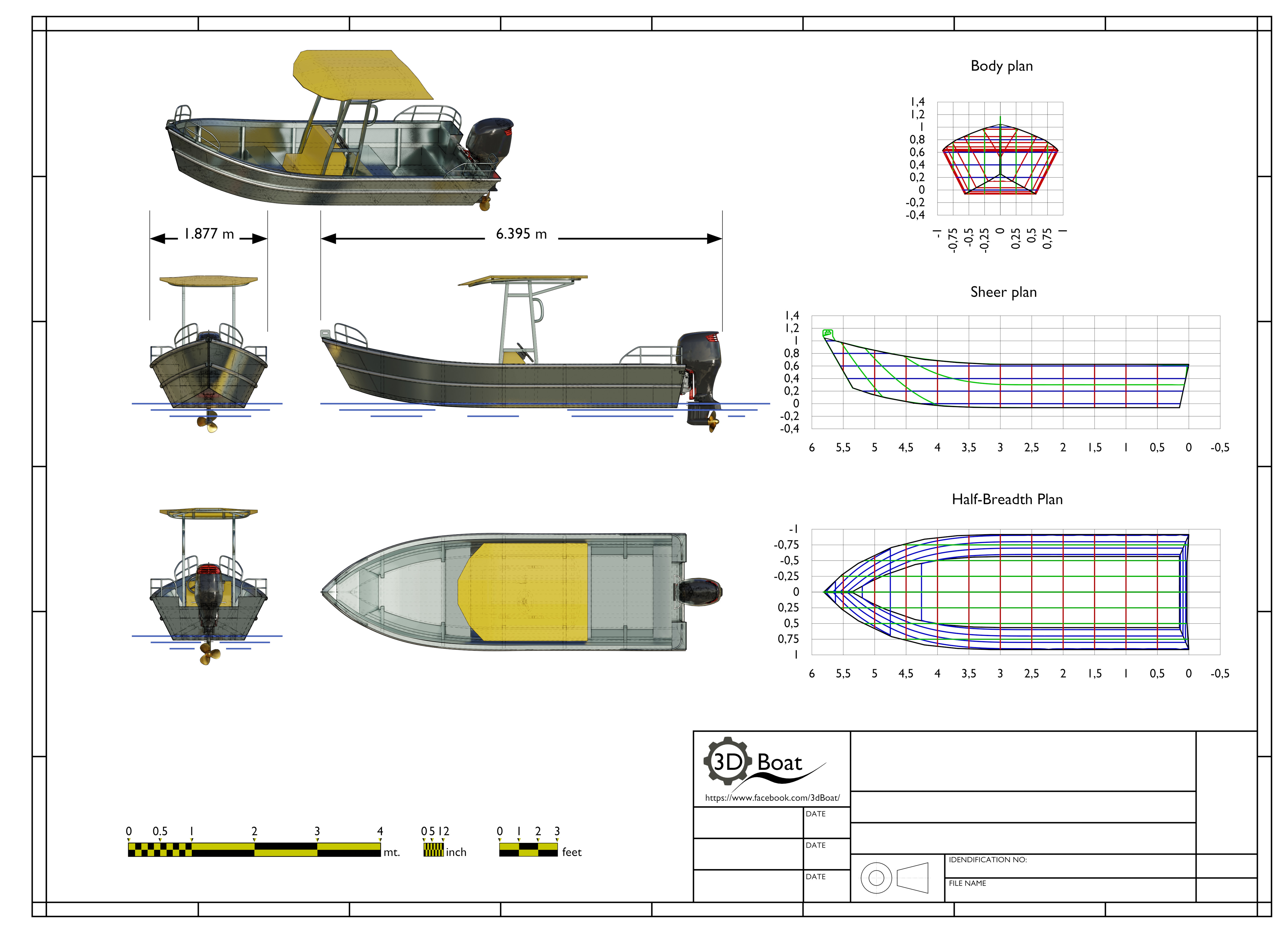
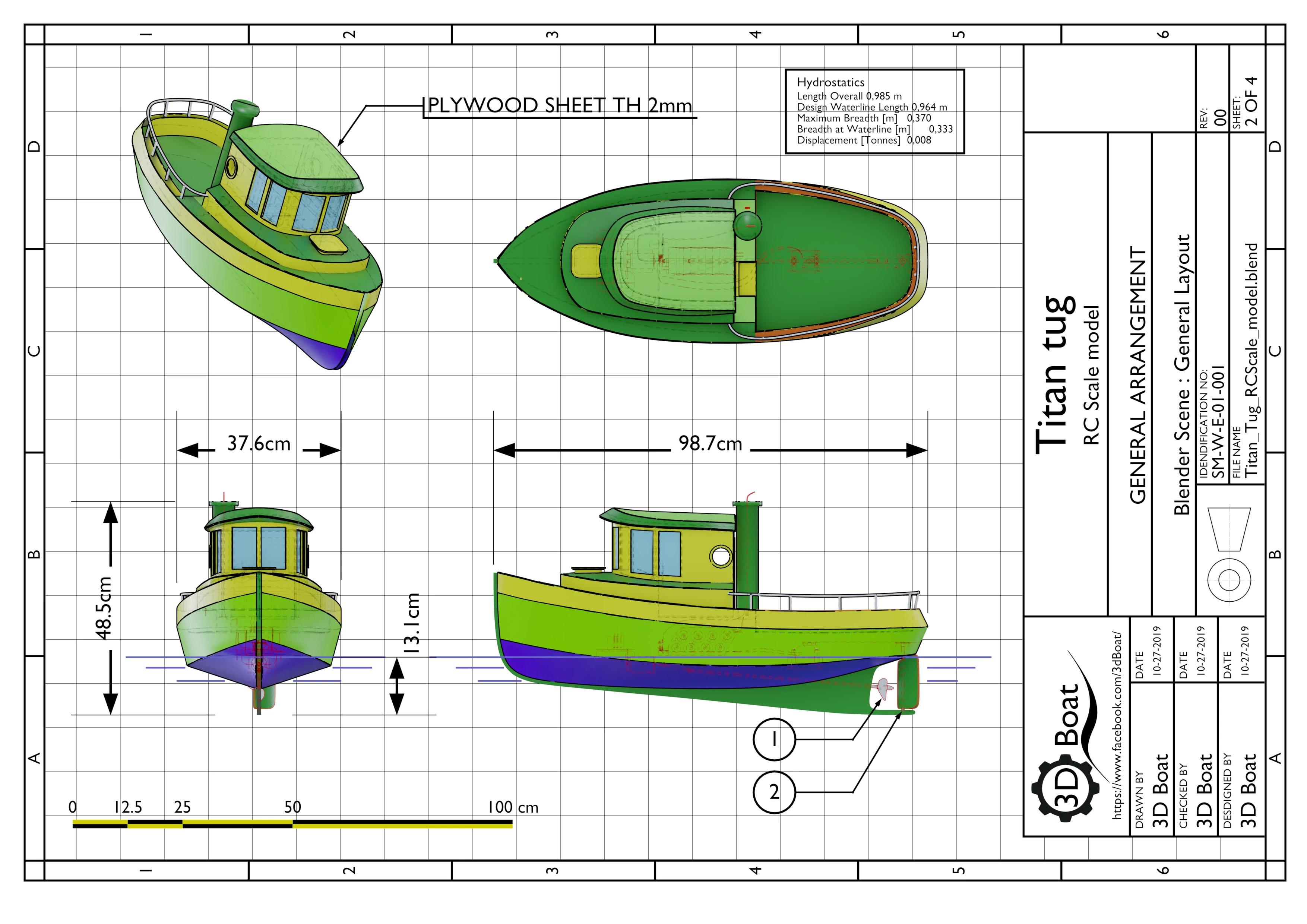
These images was made with freestyle exported render and converted into DXF then edited in 2D CAD.
Wow that Cat is a nice piece of work. The hull cavity looks tricky! I’m interested in modelling a sailing dinghy- do you work from the table of offsets and generate a “vertex cloud” that then becomes the mesh? Or is the mesh imported from another piece of software? I’m struggling to work out the best way to go about it.
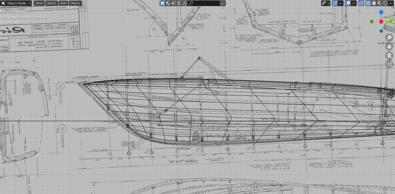
I don’t work from table offset, I Make the hull directly in Blender from linesplan at the beginning and sometime from sketches, or now modelling directly with specs or photos
I think to adopt this type solution in Blender, the Tab Layouts should have something like “Drawnings” and as quad to modify parts of this quads like Layers with camera results as immersion in one tab, the apply this type drawning_template from scripts.
Hi the titleblock is sometime in mesh and other with curve imported from a DXF template, and I don’t use Grease Pencil on these elements as for dimensions etc. but only a material with emission at 1, color depend on necessity.
With titleblock made by curves you can easily set a thickness with curve geometry and if then insert as an instance your template in a scene and scale it to include the layout you can have all update for the layout in the right way.
I arrange the drawings elements in a scene, the project in on other, and the layout with view in other scene where I add, collection instances of the projects, and the ISO template the I scale up 10, 20, 25, 100, times to include the whole objects and I do a rendering of the drawings.
Making the template in other scene allow me to set the right thickness of lines of the titleblock with correct fonts height.