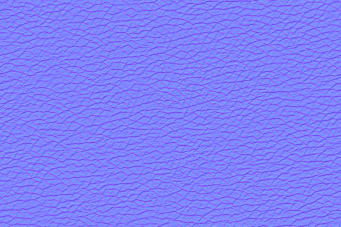
I am trying to add detail to skin on a model I made in Blender. The best method I found was to use a multi-channel displacement map as my machine struggles with high-poly meshes (for use with the “baking method” in which I would manually sculpt details and project them to a low poly mesh) and I think using an actual skin scan is more realistic.
The few tutorials I found online like this one (https://www.youtube.com/watch?v=mLIu33_mV-8) hop from Blender to other paid programs (at 6 min 34 sec) which are beyond my budget so I wish to complete the workflow in Blender v2.93.1. In the linked tutorial, the artist texture paints the map onto the model and exports a .exr file from which he extracts the channels in Substance3D and somehow projects them onto his smooth model.
I bought the skin texture from Texturing.XYZ and tried to do this myself but I have been stuck. Is it possible, and if so, could someone advise how to do it?
Welcome, i’m not quit sure what you are asking. There are posibillities to paint project or just paint a texture in 3D directly onto a texture, you can ad multiple materials and it is a bit tidious to reassign them to selected polygons in edit mode, but with this it is posibile (i just found out,because of your post , simple switching between textures does update in the vie but draws oon different textures ) to paint different our textures. And if you ask how the artist exports the exr and use it in SP… well it’s the uvmapped texture isn’t it.
Yeah, I don’t know if I described it well. But essentially I am trying to avoid hand sculpting (3D texturing onto a smooth model) the details of skin with a texture brush. I want to use a hi-res face scan, like the ones from TexturesXYZ) to add the details efficiently and realistically. For my skill level, doing it manually and texture painting a patch of pores with a texture brush won’t give me the best results. Someone on Instagram said Blender cannot do this, but I couldn’t help wondering if perhaps HE doesn’t know how to do it, so I asked the community in case he is wrong.
Had you never seen it done like that till you saw that video?
You can do most of what you saw in the video in Blender, but is not an easy process, and if you want to use displacement maps you are going to run into a slow response from the amount of high-rez needed for the displacement to work well.
I would recommend switching to a Micro-Normal workflow as it will not result in the drain on your system or right out Crash to Desktop you may have.
You can use the built-in texture paint with Projection using the maps from XYZ to get
some if not all of the textures and then combine them with micro-normal maps to get the ( Illusion ) of the displacement…the results can be very good even in EeVee which I use almost exclusively.
There are Free alternatives like Quixel Mixer to use instead of Substance…Skipping the work in Zbrush as you have the maps from XYZ!
Gimp instead of PS, etc.
Here is an example…I bumped up the roughness and the micro-normals so you could see what it looks like…and this is an EeVee screen-grab!
But he is refining the scan with micro displaceing or painting details…
It’s always a bit weird hearing people saying that one programm can’t do things another can. Sometime it’s just a liitle different and of course sometimes it’s another category of clientel.
Using other photos reference and pre unwraped ones, using scanned material or whole bodyscans … are you serious? This is evolving ever since… I saw making normalmaps by photographing the real thing with lights from left, right, above and from bottom, recoloring and mixing to a normalmap.
The micronormal result is fantastic!!! It sounds like a great work-around if it can’t be done in Blender as I saw it in that video. Where can I find material on how to do this? Or if it is not too much to ask, could you give me bullet points of how to do it?
Ok, so I’m familiar with this video, and here is what I did for all 3 of my most recent character projects.
Forget the part when they take the map into Zbrush and export a final map. It’s not necessary. (assuming my memory serves, and this is that video)
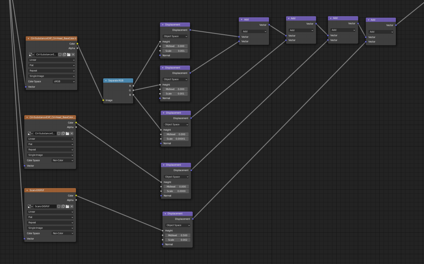
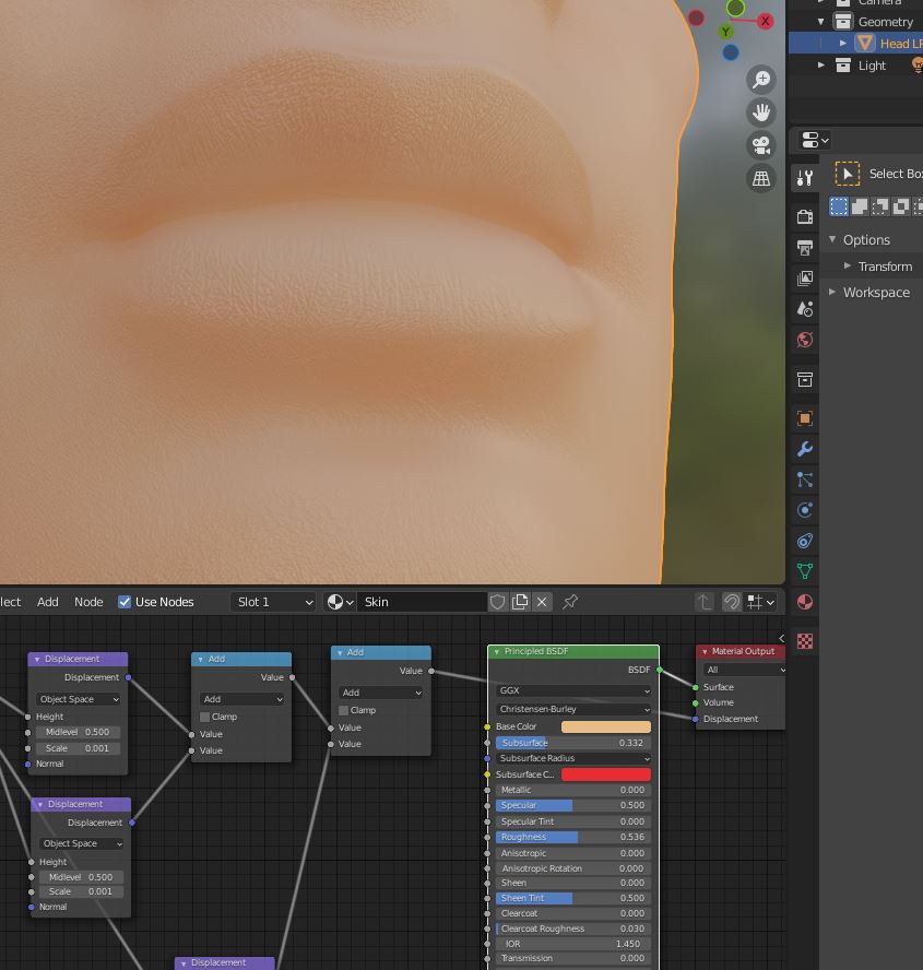
All you need to do, is split the displacement map into the R G and B values in Blender, and control each with a separate displacement node. You can then use Vector Math nodes to combine them all.
This gives you the fine control over the 3 channels: secondary, tertiary and micro
Note: the values you need to use will depend on the object scale. In real world scale, you will need to set your values very very low! Like 0.000006 kinda low. It’s dumb, but it is what it is.
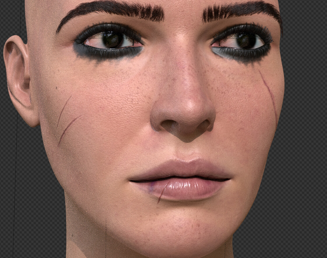
You should get good displacement off the bat, without the need for stupid poly counts, or adaptive subdivisions.
Here is an idea of how it looks using this method on one of my characters:
I don’t know why I spent the whole week struggling and asking people on YouTube and Instagram when I could have come here first. Thank you so much for this. I will try to replicate it as you have done it. Let me try and then I will report back.
Nope. If you’re exporting displacement, assuming the export file type supports multi channel, you just plug the one image in.
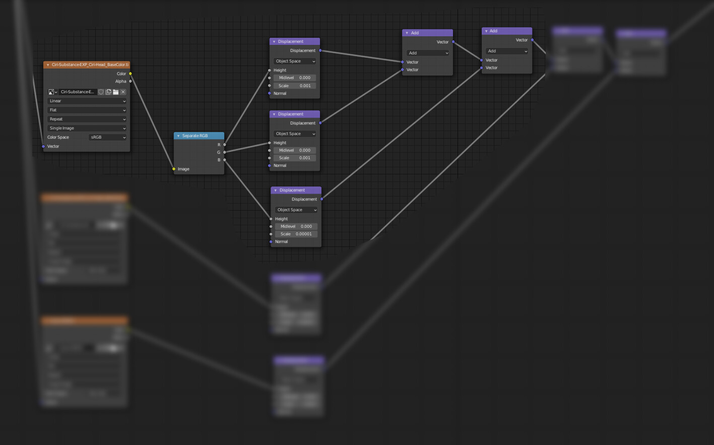
I forgot to mention…the top one here is all that’s needed. My bad. I confused myself haha. The bottom two image nodes in this example are completely unrelated. So only look at what goes into the Separate RGB node.
LOL, I tried to quickly delete the final part before you could read but I was late. I realised the node breaks it up into three channels. Okay, I am following. So only the top texture node is needed. What is connected to the final math node on the far right, Material Output or roughness on the P-BDSF? And what is on the far left feeding into the image tex node?
Set your midlevel to zero. Though it’s 0.5 in most places, for some reason, that value appears to be 0 in Blender. But see which one is better. For me, using XYZ textures, it’s 0.
For calibration (getting the values right) I normally use a simple mid to dark grey diffuse matt (Just turn off SSS and turn roughness up to .8 or something to get a better indicator) Just shows all of the details more clearly.
I’d also suggest using the Vector Math node aswell instead of the regular math node, just to make sure you’re plugging vector into vector. (purple into purple)
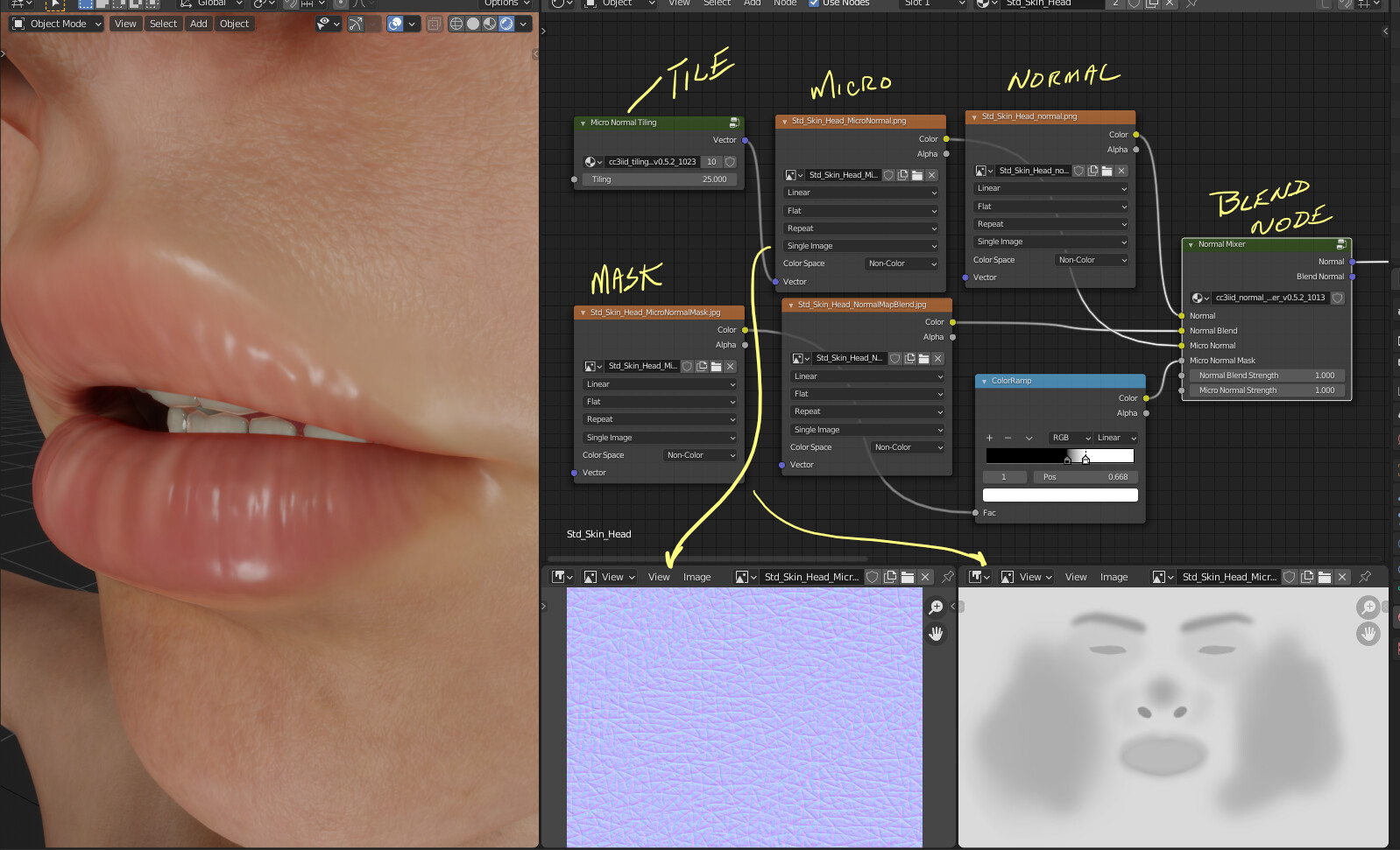
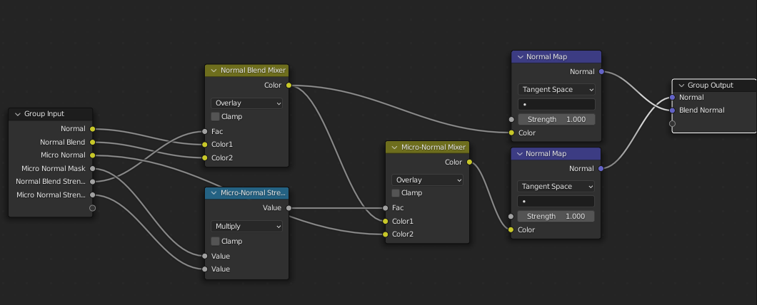
It is just a basic Blend of your Character Normal Blended with a Micro Normal and controlled by a Mask…
All of which can be done in Blender…
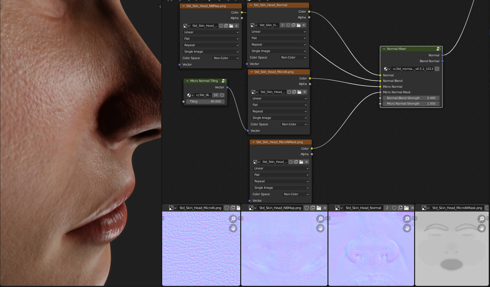
Another example and I increased the Micro as well as changing the mask so the difference is extreme… The other nodes ar just created in Blender making a Group Node, to input the Normals and Blend them as well as the strength…
I can’t believe you get such great results even in Eevee. I’d come to think it is only useful for sneak peeking what Cycles will do. I will get a Micro-normal texture and try this. I knew there was a way without using all these other programs. Thank you so much for you help!
Hello colleague, check this thread from blender artist, I hope it will be very useful for you.
It is about a small but powerful application called insanebump.
It is application and plugins for gimp.
Would you be so kind to explain your Blend Node workflow and creation of the Group nodes?
I’ve been looking all around for this method to control my skin details and this is the only clue near a solution I’ve found so far.
It’s not that complicated once you know what needs to be done…
First, you need to obtain a Micro-Normal map to use and combine that with a Normal map with a Mix RGB node using a Grey-Scale mask to control the areas that the normals will affect. ( that’s basically it…)
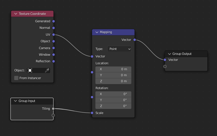
Then there is a created node group for the Normal Maps mixing…
It contains the following ( Note: I have an additional Normal map that adds a deeper pore look 3rd from the Left in the bottom of the 1st image…)
 , simple switching between textures does update in the vie but draws oon different textures
  ) to paint different our textures. And if you ask how the artist exports the exr and use it in SP… well it’s the uvmapped texture isn’t it.