Cycles PBR thin film interference, iridescence and metals

[January 2025 Update / Blender 4.3+:]
As these node groups / OSL scripts thankfully are becoming less relevant now with the partial support of thin film interference in Blender 4.3, I changed the three thin film materials that benefit of it to use this feature of the Principled shader. The visual results may change slightly, but speed is much improved for these three materials according to my limited testing. If interference on conducting materials becomes available in Blender, I’ll further update this file. I also added a lot of info on how to hook up these nodes to a shader.

Get the Blender 4.3+ materials from here.

The file compatible with Blender 3.3+ remains available below.

[October 2022 Update / Blender 3.3+:]
I updated the OSL script to use the current language features and made GPU-compatible nodes from it with OSLPy. The output is fully benchmarked against optical models I used as a scientific researcher in nanophotonics. Get the Node group (Blender 3.3+) plus all materials shown below here.

OSL Scripts used to generate the node are here. Note: you’ll need a modified OSLPy in order to generate the node groups.

Example output:


Blend file (4.3+)
Blend file (3.3+)

Background

See the presentation or read on: 
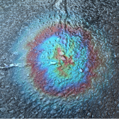
The colors of soap bubbles is caused by a phenomenon called thin-film interference. Cycles does not natively support the calculation of this effect, but I have implemented a model which, within the limitations of Cycles, gives accurate results. In order to calculate accurate results, the Node Group needs the refractive index of the materials involved.

Next to soap bubbles and other glassy materials, oxide layers on metals can also be accurately calculated. Below the heating of iron is shown, where an increased temperature corresponds to a thicker oxide layer, which in turn causes the color to change.

iron_heat

The blend file above has the following material presets (change the material of the test object to view)


These materials are examples of how the Node Group can be used to calculate common interference phenomena in Blender.

Using the Node Groups

Layer on glass

  • Transparent base material
  • Top layer can be conductive or transparent material
    • Examples: metals and oil, water

This node group supports the well-known soap bubble effect, which was the reason I started to program interference shaders in OSL back in 2016. Though the soap bubble effect can now be obtained quicker with the Principled shader, this node tree still supports effects that the Principled shader does not, like absorbing or conducting materials for the thin film.

The noodle below shows the basic setup

  • Inputs:

    • n: the refractive index of the base layer (float)
    • n_layer: the refractive index of the thin film (float or vector of 3 floats for RGB)
    • k_layer: the extinction coefficient of the thin film (float or vector of 3 floats for RGB)
    • d: the thickness of the thin film (in micrometer)
    • Normal: plug in the normals if effects such as bump mapping are used and the thin film shader should use the altered normals when calculating the reflected color.
  • Outputs:

    • R: the reflectance of the thin film, per color (vector of 3 floats, RGB)
    • T: the transmittance of the thin film, per color (vector of 3 float, RGB)

For people used to a complex refractive index, n_layer is the real part, and k_layer is the imaginary part. The thickness d can be driven by another node, that is, it can depend on location and time. To obtain a shader, the reflectance drives a Glossy shader and the transmittance drives a Refraction shader. Note that for energy preservation reasons a glossy shader and refraction shader are added with the Add shader. As an example of what is not yet possible with the Principled shader, here’s a thin layer of gold on top of a plastic base material. Using a thin gold film is common in astronaut helmet visors as it stops IR radiation but allows part of the visible to penetrate (see the green hue of the white light that is emitted).

space_helmet

Conductor (bonus)

  • No interference, but can be used for plain metals and semiconductors
  • No transmittance, as the base material is assumed to absorb and reflect light only.

Node setup:

  • Inputs:

    • n: the refractive index of the base layer (float or vector of 3 floats for RGB)
    • k: the extinction coefficient of the base layer (float or vector of 3 floats for RGB)
    • Normal: plug in the normals if effects such as bump mapping are used and the thin film shader should use the altered normals when calculating the reflected color.
  • Outputs:

    • R: the reflectance of the thin film, per color (vector of 3 floats, RGB)

Hook up the output to a glossy shader, or to a Principled shader’s Base color and set metallic to 1.0.

Layer on conductor

  • Use for oil stains and oxides on metals, oxides on semiconductors, etc
  • No transmittance, as the base layer is assumed to be absorb and reflect light only.

Basic node setup:

  • Inputs:

    • n: the refractive index of the base layer (float or vector of 3 floats for RGB)
    • k: the extinction coefficient of the base layer (float or vector of 3 floats for RGB)
    • n_layer: the refractive index of the thin film (float or vector of 3 floats for RGB)
    • k_layer: the extinction coefficient of the thin film (float or vector of 3 floats for RGB)
    • d: the thickness of the thin film (in micrometer)
    • Normal: plug in the normals if effects such as bump mapping are used and the thin film shader should use the altered normals when calculating the reflected color.
  • Outputs:

    • R: the reflectance of the thin film, per color (vector of 3 floats, RGB)

Hook up the output to a Glossy shader, or to a Principled shader’s Base color and set metallic to 1.0.

Double layer on conductor

  • Two thin films that interfere with each other as well, on top of a conductive layer
  • Use for very strong interference effects, such as special car paints
  • No Transmittance output as the base material is assumed to absorb and reflect light only

Basic node setup (here based on Car Paint 1):

  • Inputs:

    • n_top_layer: the refractive index of the top film (float or vector of 3 floats for RGB)
    • k_top_layer: the extinction coefficient of the top film (float or vector of 3 floats for RGB)
    • n_middle_layer: the refractive index of the middle film (float or vector of 3 floats for RGB)
    • k_middle_layer: the extinction coefficient of the middle film (float or vector of 3 floats for RGB)
    • d_top: the thickness of the top film (in micrometer)
    • d_middle: the thickness of the middle film (in micrometer)
    • Normal: plug in the normals if effects such as bump mapping are used and the thin film shader should use the altered normals when calculating the reflected color.
  • Outputs:

    • R: the reflectance of the thin film, per color (vector of 3 floats, RGB)

Hook up the output to a Glossy shader, or to a Principled shader’s Base color and set metallic to 1.0

Values for n and k

Choosing values for n and k

The shader allows you to enter the values to use for the refractive index (n) and the extinction coefficient (k) for the red, green and blue channels. These values are often listed as a function of the wavelength of the light, for example at refractiveindex.info. The node groups use:

  • 650 nm for red
  • 532 nm for green
  • 450 nm for blue

Picking the refractive indices and extinction coefficients at these wavelengths will get you a long way, but see below.

Optimized values of n and k for metals

So-called spectral renderers use the tabulated n and k values for each wavelength in the visible light spectrum to calculate what a material should look like. Cycles on the other hand only uses three color channels, one for red, one for green and one for blue. You might wonder what n and k values would best approximate the results of a spectral renderer. I have optimized the values of n and k for the metals that are included in the blend file to look as close as possible to the output from a spectral renderer, when the metal is illuminated with white light (D65 white point) and the sRGB color space. I included the color accuracy for transmitted light in the case of metals, to get a good color fidelity when these metal films become thin. The blend file contains node groups for the included metals and oxides that look like this:
image

Just hook up n to n and k to k and you’ll get the behavior of that material in your shader.

Extra

As back in 2016 the Principled shader did not exist, I whipped up a “metallic shader” to simulate the metallic effect in car paints and to include a (physically-correct) clear coat on top. I’m not saying it’s fit for any purpose, but it might be useful. The node looks like this:
image

  • Inputs:

    • Metallic color: the reflectance, typically the R output of one of the nodes above
    • Metallic roughness: the roughness of the underlying Glossy shader
    • Speckle size: size of the metallic flakes in the car paint
    • Speckle amount: how much the speckles show up in the render. Zero for off, one for fully showing.
    • Clear coat IOR: the refractive index of the clear coat on top of the car paint.
  • Outputs:

    • Shader: a reflecting shader

Example (car paint 7), with Metallic roughness = 0.0, Speckle size = 0.4, Speckle amount = 0.4 and Clear coat IOR = 1.5.

19 Likes

Thank you.

Just another example:

Do you have to do anything to get this script working.

I copied the text - pasted it into the text editor, named it - then added the script node and tried to load it - however the code just keeps throwing an “invalid syntax” error on line 1.

nice looking

can you give the math model followed for this effect
to understand what the model is

thanks
happy cl

Video showing angle-dependent color (smooth glossy shader for speed):
https://dl.dropboxusercontent.com/u/5326890/angle_dependent_color.avi

Did you try the .blend file that I also put online?

Thanks :slight_smile:

Here’s a starter: https://en.wikipedia.org/wiki/Thin-film_interference

Not how I implemented it, though. I implemented this formula:


where r(p,s) is the complex reflection amplitude for light of a certain wavelength at a certain angle. This depends on the reflection coefficients of light at the interface with the film (r12), the reflection coefficient at the interface with the substrate (r23) and the thickness (d). See also, for example, L. Novotny & B. Hecht, Principles of Nano-optics, Ch. 2 & ch. 10.

Yes - it’s ok - muppet me hadn’t ticked the OSL checkbox on the render tab

edit: Just been having a play - very cool.

Glad to hear! :slight_smile:

any chance this could be use to do some other effects like sea shells surface ?

thanks
happy cl

Yes, I think you can get quite far, though I don’t have the exact behavior of mother of pearl firmly in my head.

but your OSL does only circular shapes I think so this might require some re shaping or deformations to look like mother pearl !

thanks
happy cl

You can modify the thickness d as a function of location. Set it to 0 to turn off interference, set it to some value to turn it on. Set it to a specific thickness to get a certain color at a certain angle. You could even use one of the colors (R, G or B) to drive another color map. I’m not sure how far you can push it, but it would be a start.

Edit: for the soap bubble animation I started out with a homogeneous thickness across the bubble, slowly decreasing the thickness at the top and increasing it at the bottom to simulate gravity. It’s just an example of what you could do

I did not learn a lot on OSL so cannot really begin to find a logical way to do it !

happy cl

You don’t need OSL to change the thickness, just plug something into the connector for d and you’re done :slight_smile: Look at my blend file, where I’ve added nodes to locally change the thickness in the last scene in the file.

I will try it tomorrow got other problems to solve for today! LOL

thanks
happy cl

do you know there is a thread for all OSL things
you should add your in that thread too

happy cl

Yes, I will do that, thanks! :slight_smile:

I also fixed a bug, so I’ve updated the OSL script. See first post for the update (blend file and script)

for the 2 files or only first one ?

I mean does it affect the other PBR metal too ?

happy bl