Hi Kushiro. I just bought Grid Modeler and have only played around with it for an hour or so. I love the absolute grid, this was really the main reason for getting it, because so many modeler add-on are lacking in precision features like this IMHO.
But I do have one issue with it that I think could be improved fairly easy. If I start with the default cube and Ctrl + scroll to change the grid “division” it goes from 20 to 22, and that makes it not absolute any more. Maybe it would be more logical if it was divided by 2 or even 10 to keep it more absolute-ish, so going from 20 to 40 or 200 respectively. Going straight to dividing by 10 would make it mutch denser, but would keep it on absolute grid regardles and the division would be the same on every scroll “level”. A more gradual way might be to first divide by 2 on the first scroll, 4 on second scroll and 10 on third scroll, and then start over with 2,4 10, then 2,4,10 again and so on and so on. Its might be a bit dificult to explaine in text, but say if you have started with a 1x1 plane with one Grid Modeler grid square covering the entire plane to begin with, so 1m x 1m, if you scroll onece it would devide by 2 making a 2x2 grid where each grid cell is 0.5m by 0.5m. Scroll again it would “recalculate” from the original 1m x 1m grid, divided by 4 giving a 4x4 grid where each grid cell is 0.25m x 0.25m. On third scroll, “recalculating” from original doing a division by 10 from the original grid making it 10x10 grid size with grid cells of 0.1m x 0.1m. Then you are down a 10th and you could “start over” with the same pattern. Dificult to explane in text only but I hope you get what I am getting at.
If there could be an option for a thicker line every 10th absolute grid line it would also help a lot when you need fine placement instead of counting every cell from an edge, or some feedback with the absolute position of the current grid position before placing a point.
I mostly do ArchViz. It is already very usefull for that, but with a bit more features like this you could easily make this a go to add-on for ArchViz users in addition to hard surface modeling IMHO.
Gonna go dig a bit deeper in the add-on now, realy enjoing it so far Turned in to a bit of a rant this, so let me know if you want anything clarified.
Writing things out sometimes trigger the brain, and I think I already came up with a simpler/less intrusive solution to my “issue”. Sorry for the double post, but you can basicaly disregard most of my last post, but keeping it up for context.
I think the “Grids : 20” confused me in absolute mode. Not sure why it says 20, to me it would be more logical if it says 10 (so devided by 2 basicaly), as one absolute unit is divided into 10 in all cases I have tried so far when it says 20. Doing calculations on that basis in your head it gets alot easier at a glanse. A nice addition would be adding a number behind the grid number indicating the size of the smallest cell, so something like if you have a 1m x 1m plane devided into a 10 by 10 grid it could say “Grids: 10 (0.1 cell size)” or something similar. and then adding a thicker line to the grid every 10x10 grid cells would make it alot easier to find the placement and dimentions of the shape you need to draw with precision.
One more request. For the Boolean Cut, could we get an offset option that goes in the normal direction from the shape drawn, so basicaly offsetting the starting shape part of the boolean but only in the oppositt direction of the depth. The boundary offset seems to go in “all” directions, it would be nice if there was an option to only add to the side you cut from, then you would have a precise cut. I tried by using up arrow to go a step out from the object and then draw and do a cut, and that works, but some times that “re snapps” the grid and I cant seem to realign it when I am one step off the surface/face, also it adds a lot of clicks, but that is my closest workaround I found so far.
Been looking into this plugin, looks amazing and I’ll be buying a copy, but can someone please recommend a video that specifically goes through the whole feature-set one by one?
I mean like a tutorial/feature-set demonstration all-in-one sort of thing.
[EDIT]
Forget that, just searched again and for some reason I see one now, damned YouTube
Hello ! Sorry for late reply
About absolute size, yes it divide a standard blender unit, so the grid size will be the same (on different faces).
Why it write 20 not 10, it simply means 20 grids in 1 blender unit
About the boolean cut. Blender’s boolean engine has problem, and it is not fixed yet.
Blender has two boolean solvers, one is “Fast” and one is “Extract”. Both of them cannot handle overlapping faces in boolean operation. Therefore, if there is cutter object at the border, with faces at overlapping location, the boolean will simply failed. The resulting object will has big hole, buggy, or even disappeared (more buggy).
If one day blender team fixed all boolean problems, I will consider remove the offset.
Please visit my website https://www.kushirocg.com
There are some tutorial videos.
And also in my youtube channel.
There is no video containing all features, simply it is too much, and not reasonable to be discussed in single video.
Please read the full documentation on website for all functions and usage.
Thanks for the info. I’m pritty sure it should be 10 devisions per blender unit instead of 20, but thats what I thought was the logic behind it. I managed to “hack” the text update to get it the way I wanted it anyway, so if noone else has mentioned it I can just keep my own “fixed” version, no worries.
I don’t neseseraly want you to remove or change the Border Offset, but if there was an option to have the offset just go along the normal of the original “cut shape” it would realy help with doing booleans quickly with presision. I know the limitations of the booleans, but if you just move the cut shape out a bit the issue would only be if you have a shape that has a line that is perpendicular to an edge. The workaround for that is to just use the existing Alt+scroll to expand and cut it on the next grid line instead, and you would have identical results. Does not have to be on by default or anything, even hide it in preferances if you want. I already love the addon, but this little option would make it soooo mutch more valueable for precition work.
I can draw up some images and explain more in detail what I am thinking if my explanation is not clear.
I understand what do you want, an option to have the offset just go along the normal of the original.
But this option may cause the boolean operation bug because of the overlapping faces problem,
Therefore I didn’t add it. I don’t add a feature or option that “it may cause user confusion”.
I hope that blender dev team will fix the boolean engine soon, at that time we can have precise boolean.
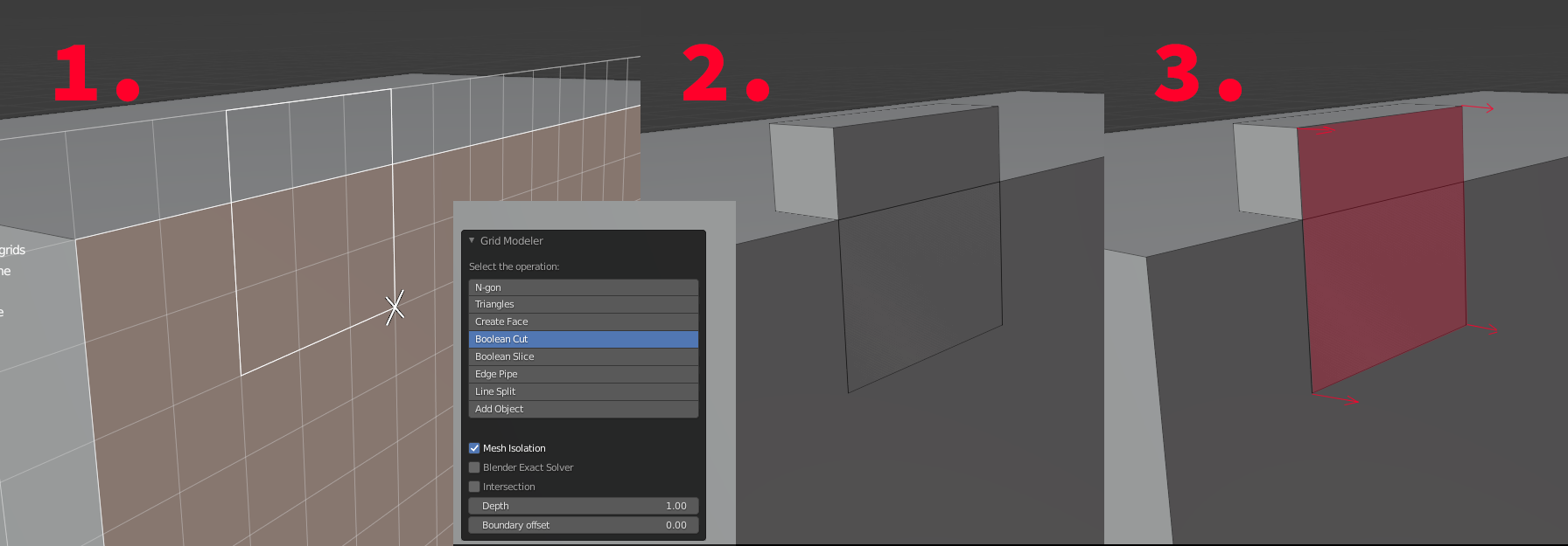
Say if I make a cut like the one marked 1. I would get the result as marked 2. when using the settings shown. And the only part on the same plane would be in the original shape, like the face marked red/pink marked 3. I drew some arrows to indicate where the original would need to be moved to solve it and you would get en exact cut as there should be no conflicting geometry anymore, so esentialy add a bit of depth in the oposit direction of the regular depth…
I do understand the part about confusing users, but it would not have to be on by default, just an option, so when anyone needs it, they could set the border offset to 0 and add the “Normal offset”, mark it experimental or whatever, but i think this could be usefull for a lot of people. Not many other hard surface add-ons have this exact functionality with the precise grid. Maybe I can try to figure it out by myself, thanks for the feedback and consideration anyway
One work round is that you move the grid plane “Up” before doing anything.
You can press Arrow-Up key to move the grid plane up.
Then draw the shapes and cut,
and then you set a zero offset for the boolean cut.
Sometimes the grid seems to snap again when I do that and gets the grid a bit off, and it also seems to sort of snap back before it does the actual boolean, leaving me with a similar result unfortunatly.
I was thinking a workaround could be to set the border offset to a whole number and just make a shape that was that mutch smaller, sy do a 1x1 and set the offset to 1 to make a 3x3, but it is not absolute it seems, if the offseting by norlmal is the hard part, maybe that could be an half way option… just thinking out loude here …
Also, did you try “Exact solver” option ?
blender team created this solver to do the overlapping face boolean (sadly it fail for some cases, but for simply case it work).
Just draw shape on face, boolean cut, then set zero for offset, and check the “Exact solver option”.
It work for simple case… not all case.
I think I tried all combinations of that too, The exact boolean is realy nice in most cases, although slow, but it seems to have issues when the norlmals or not “correct”, if you extrude a plane the wrong way instead of using a cube for the boolean for instance.
hmm, did some test with regular exact boolean and flipping normals and extruding planes. Not 100% that it would fix it, but is it possible to recalculate the normals outside on the temporary mesh you make before applying the boolean, that might actualy make it work with just the exact boolean option on … might be wrong here, but I think that might be worth a try…
hehe, to be honest it usualy does the trick for me, but it is sooooo slow I usualy fudge the geometry a bit to make the old one work instead when I don’t have time for it to update … or crash
Looks like you are already doing the normal calculations I mentioned already, if I found the right place that is !? [edit: I think i was in the wrong place now :S ] Hope you don’t mind me poking around your code a bit too se if I can find a “solution” will report back if I come up with anything. Thanks for the help so far
 Turned in to a bit of a rant this, so let me know if you want anything clarified.


")
 Hope you don’t mind me poking around your code a bit too se if I can find a “solution”