Oh man I was sure I would end up finding something better. Thanks for the pointers !
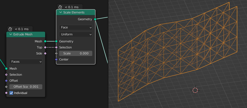
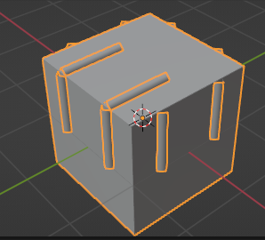
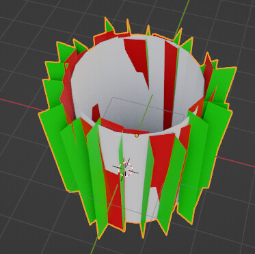
At first I was wondering how to poke the faces like you suggested but I remembered something I read on BSE. Extrude faces and scale the top face to 0 to get poked faces.
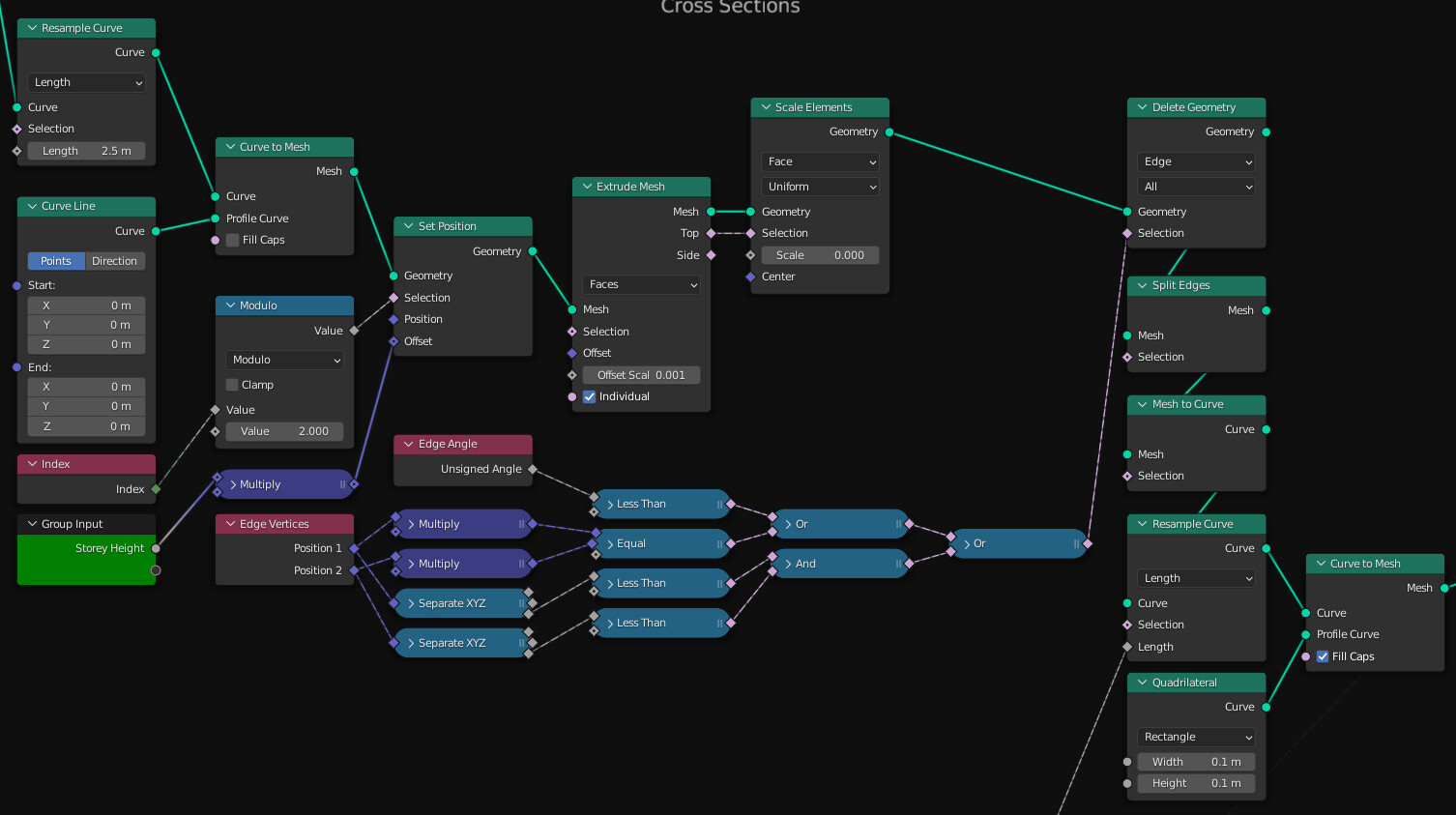
So to reiterate :
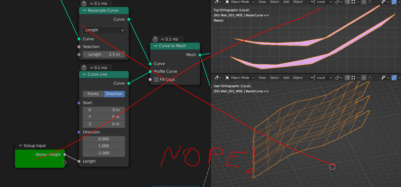
- Resample curves
- Curve to mesh, but you can’t just use the direction inside the Curve Line node because it will be extruded along the local normal (or tangent ? didn’t check)
(Edit : the Curve line direction should be (0, -1, 0) but the problem doesn’t change)
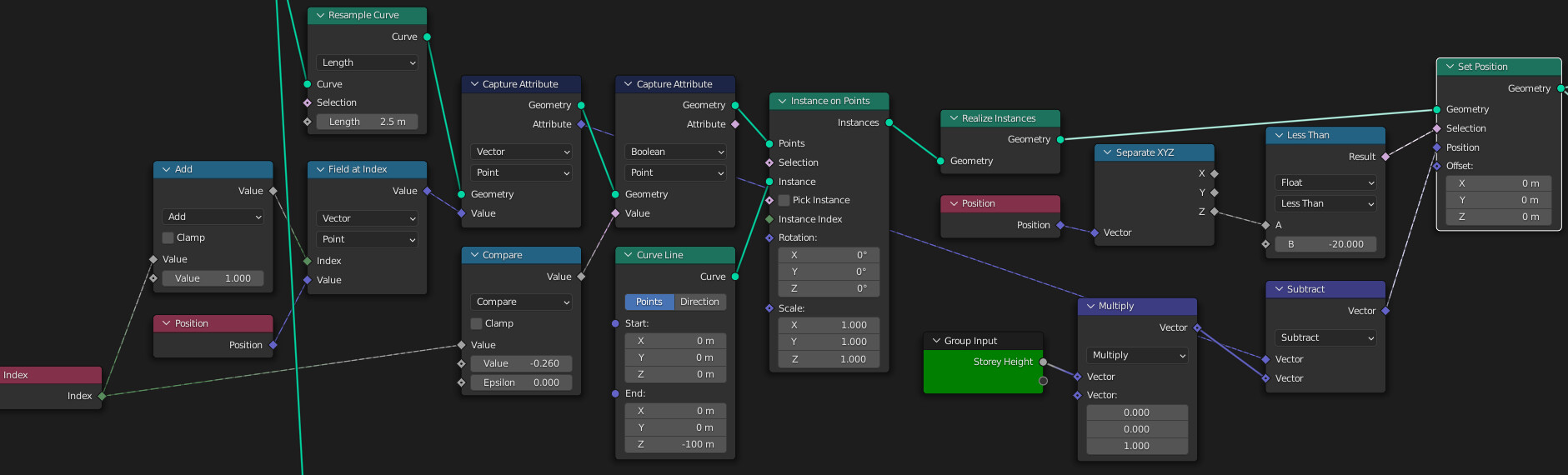
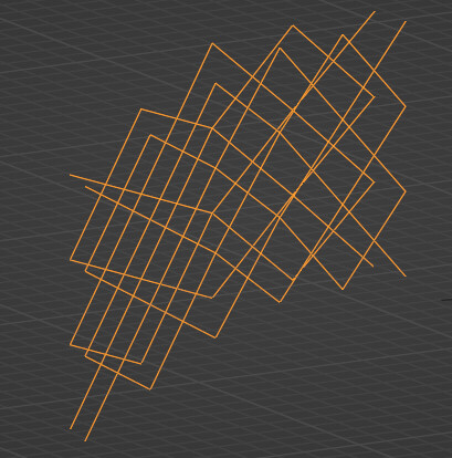
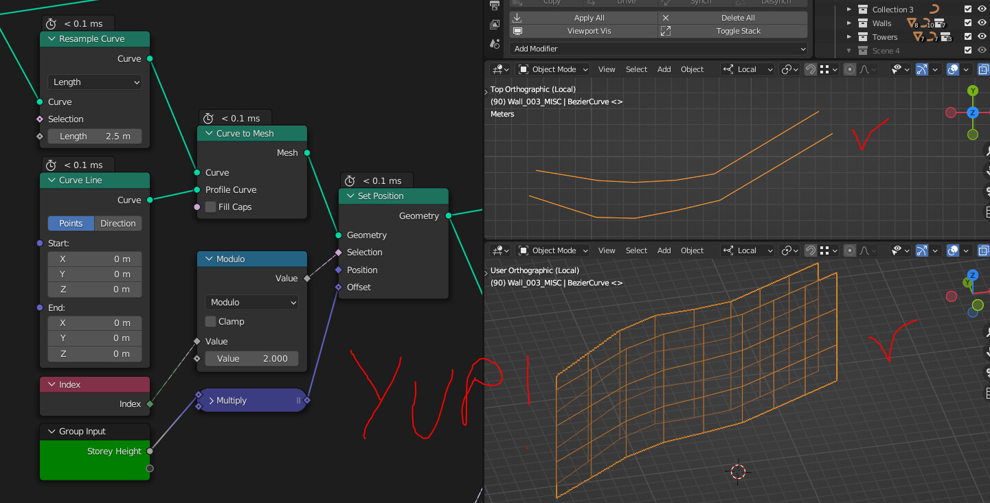
So my solution was to instance a curve with 2 duplicated control points, then offset every other point using a modulo with the index.
- Poke the mesh using an Extrude and Scale Elements with 0 scale
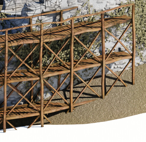
Tha was a piece of cake ! Note I used a slight offset in the Extrude because I use the edge angles to filter out the edges that are not diagonals later.
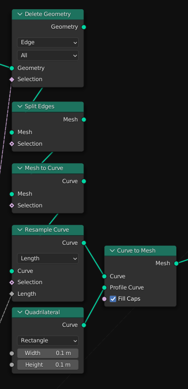
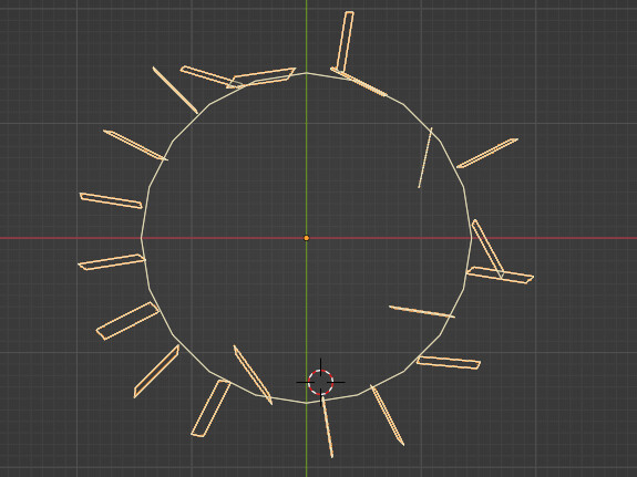
- Now we need to heat up the brain cells a bit to filter in only the diagonal edges. The selection is threefold.
First we remove the “horizontal” edges by checking the unsinged edge angle (honestly that was a shot in the dark, I can’t really explain why it works)
Then we get rid of the vertical lines by checking that the two verts of an edge’s X and Y components are the same
Then we get rid of the edges that are located below the local Z = 0, that will aleviate some computation in the boolean later on.
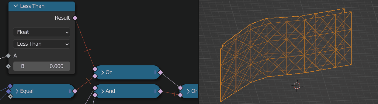
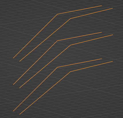
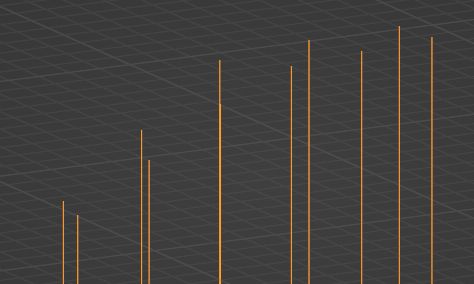
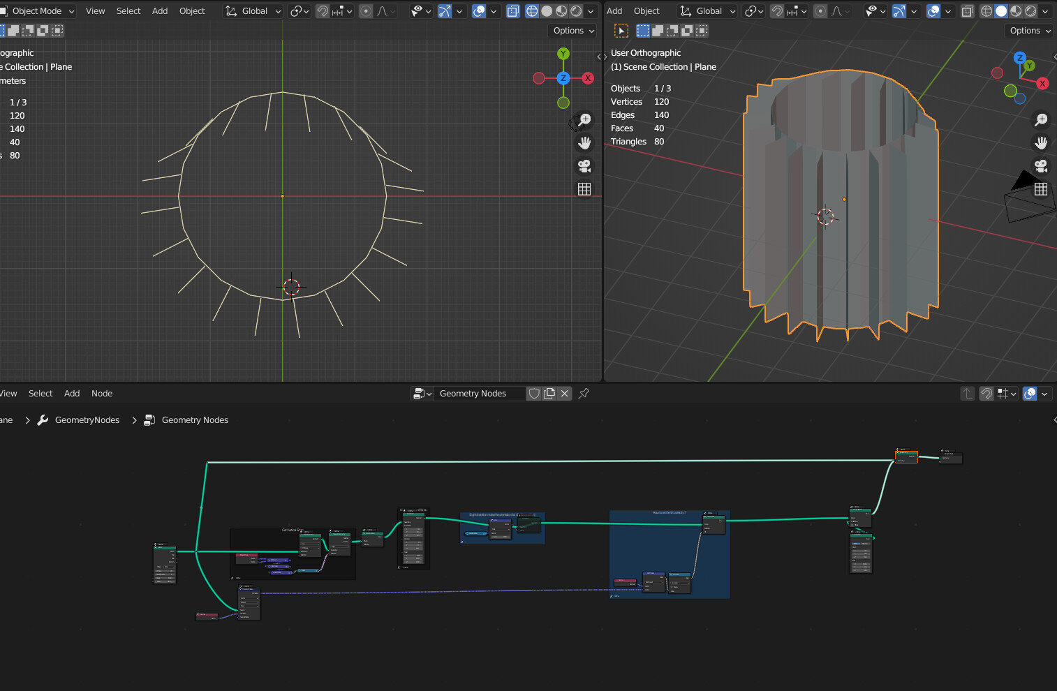
- And now we split the edges to get individual splines later on, convert them to curves, resample then using the LOD input slider, and transform it to mesh with a quadrilateral curve !
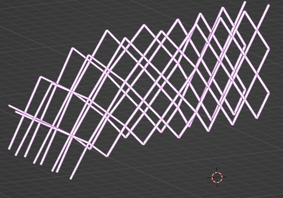
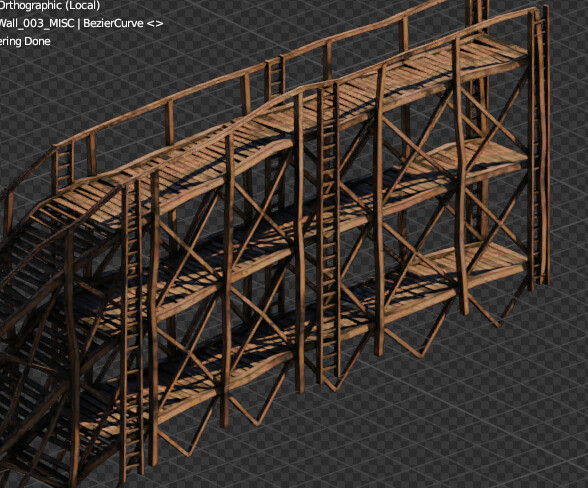
Pretty much the same result as earlier, but with way less overhead in nodes.
Here’s the updated node tree
However I did notice that this performs worse than the first solution i nterms of computation, roughly * 2 time, but it’s nowhere near the bottleneck of this tree so I’ll stick with it since it’s so much simpler !
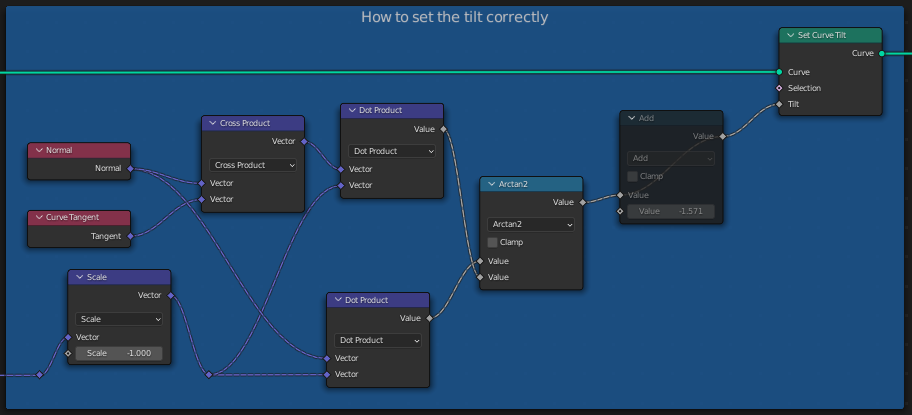
Concerning your question, that’s really funny, I think I’m stuck on a very similar thing ! Vector maths is not my forte so I usually play with every setting until it works but in my case it didn’t.
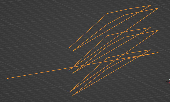
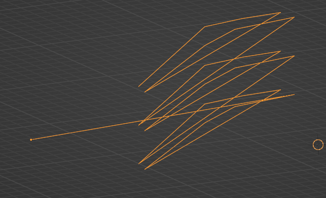
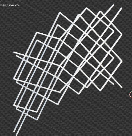
I was trying to instance ladders which are themselves a node tree I’ve showcased earlier.
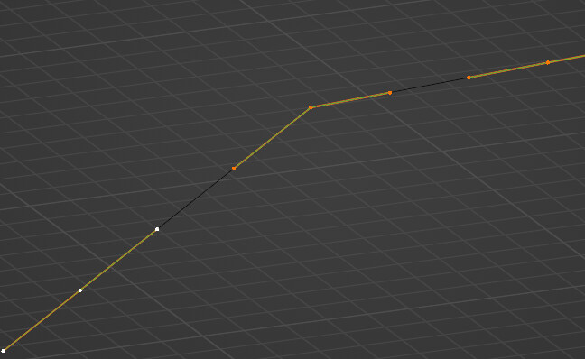
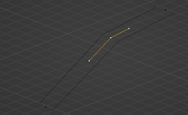
It looks Ok-ish when the curve is along the X axis
But pretty bad when it turns… i can’t figure out the correct rotation
And I can’t use the Align Euler to Vector trick because the ladders are instanced using curve lines and a curve line doesn’t really have a notion of rotation… I’m trying to play with the tilt but can’t get my head around it for now !
So I’m afraid you seem to be way beyond my level on this topic. I’ll poke around though and see what takes !
@joseph cheers, happy to share ! Don’t hesitate to ask questions or maybe show what you’re working on, inspiration goes both ways