Thanks to Your Help, the Radial Tiling Node Was Added to Blender!

Ah, the naming is a bit confusing here. "Hexagonal Tiling refers to a Euclidean tiling https://en.wikipedia.org/wiki/Euclidean_tilings_by_convex_regular_polygons using Hexagons.
But Hexagonal Tiling can also refer to tiling things on a triangular grid.
That’s probably what you want. For that an updated version of the grid texture would be necessary.

Sure, take your time. Perhaps I can help with achieving your result.

1 Like

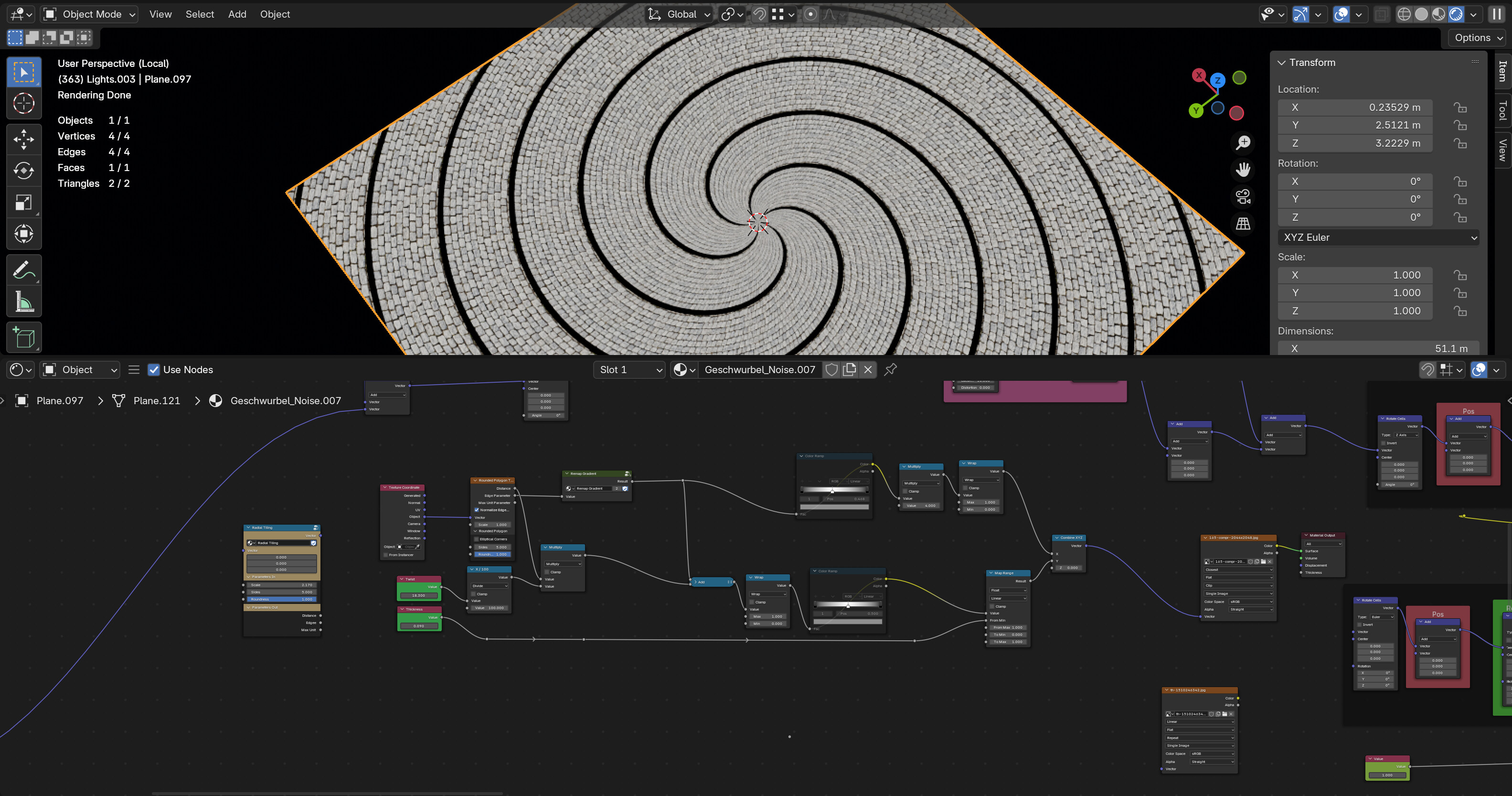
Ah, finally found how to do the spiral without seams. Would be great to also get it without distortions.

7 Likes

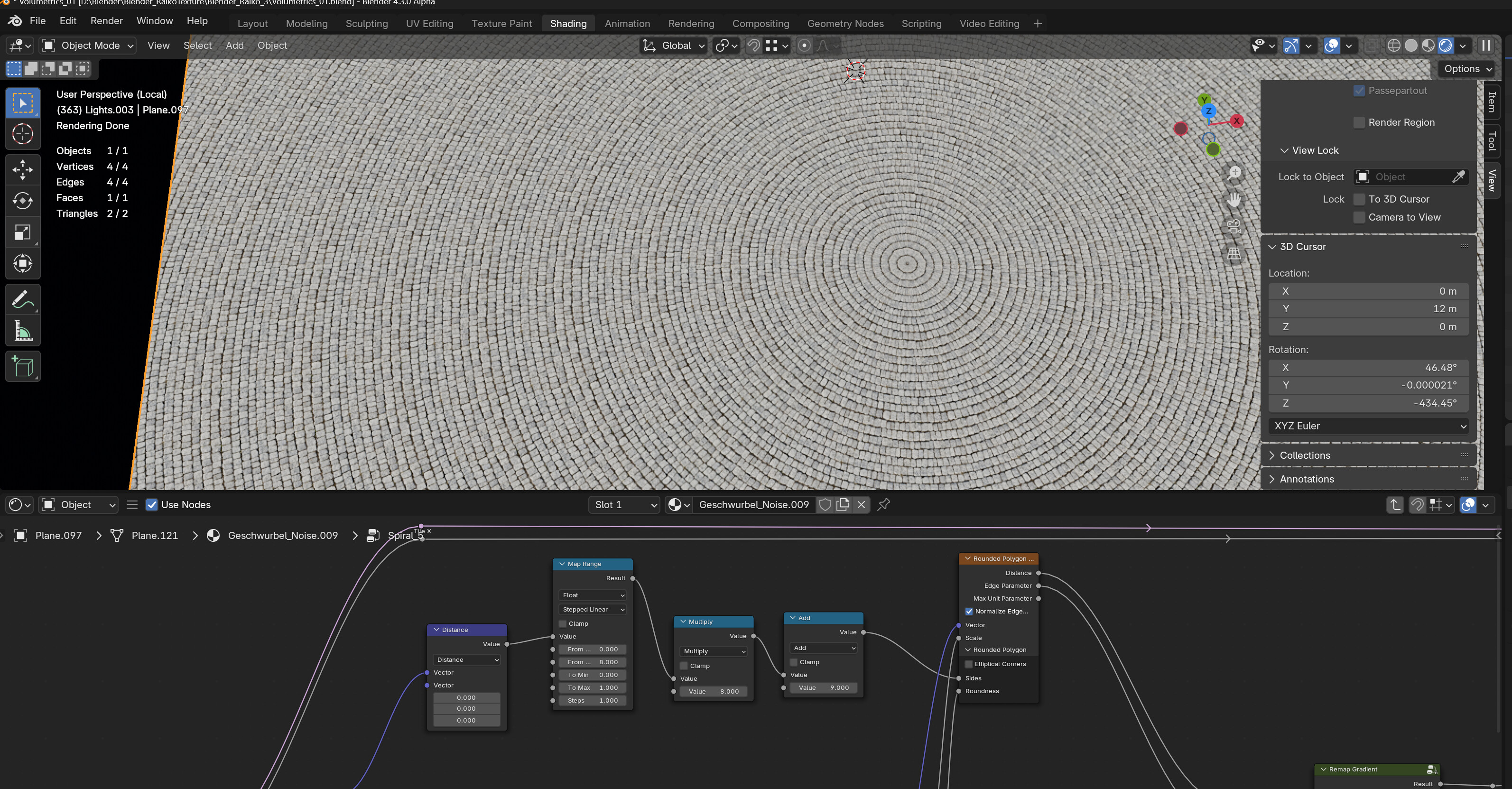
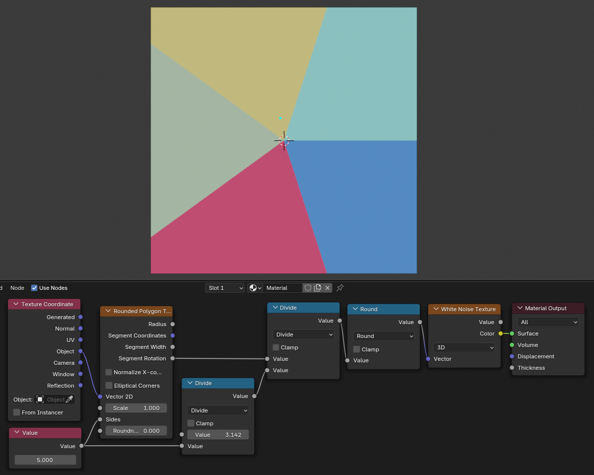
I found a neat way to keep texture sizes consistent for radial mapping. Basically the larger the radius of the texture ring the more Sides are added in the Rounded Polygon Texture:

7 Likes

Woah, that’s a really cool technique! :+1:

Update: I had a meeting about the new nodes yesterday and here’s a quick summary:

The other developers aren’t completely convinced by the current design of the Rounded Polygon Texture node yet, but Simon Thommes is going to review it sometime in the future.

As for the node groups there is still the technical hurdle of asset embedding that needs to be overcome before the node groups can be added. So development of those will resume as soon as asset embedding is solved.

8 Likes

It’s the day after tomorrow! Okay, it’s next month, took longer than I thought to get back to this. In the meantime:

Where should we be looking to keep track of that? Any of these? Which?

So I’m not sure if any of this is already outdated, if so, sorry.

What I’m attempting to achieve is:

Hexagonal tiles with interesting patterns (Benny_G’s flowers, etc) stamped into them, using (as much as feasible) the new Raiko stuff in this topic.

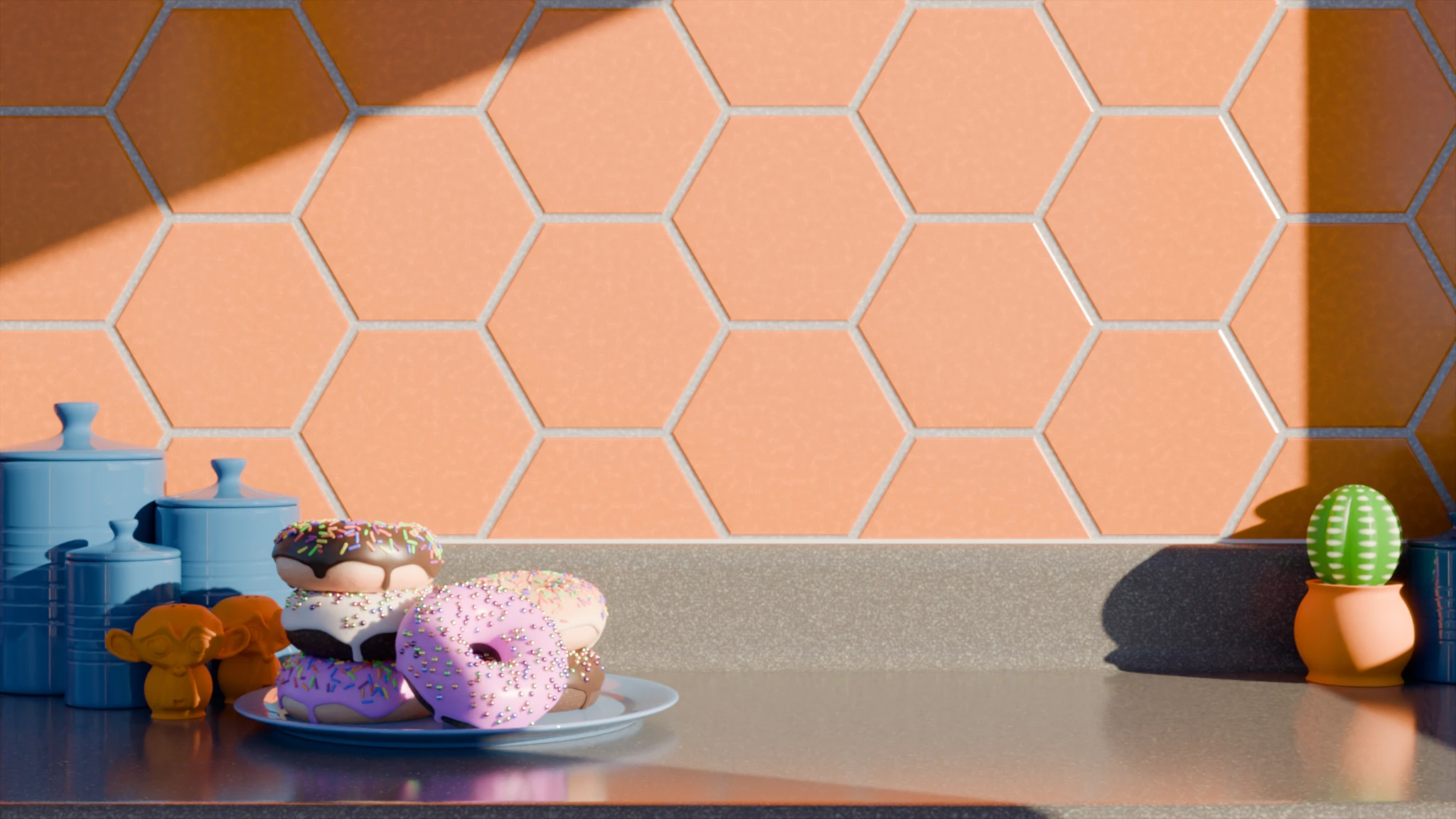
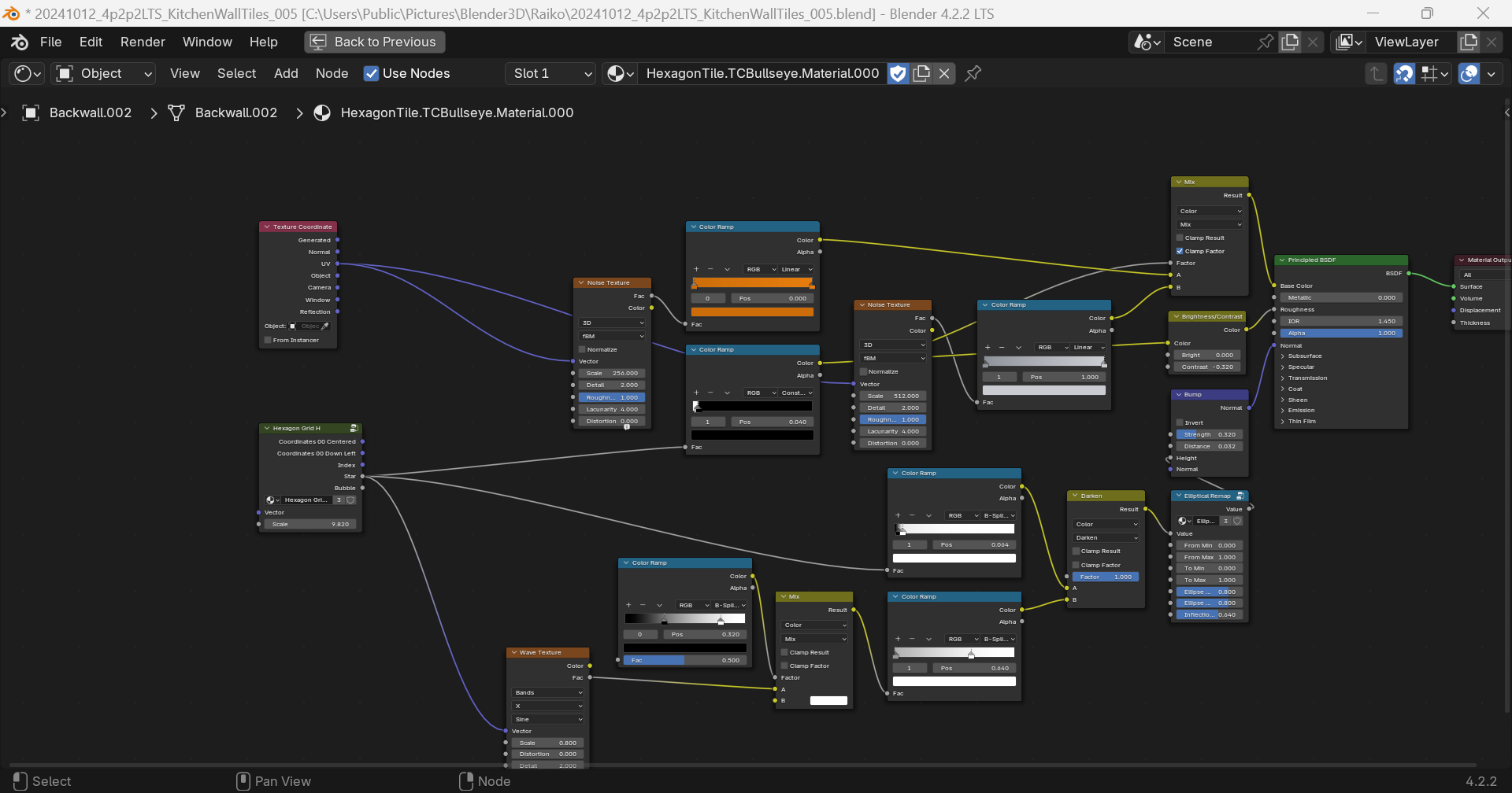
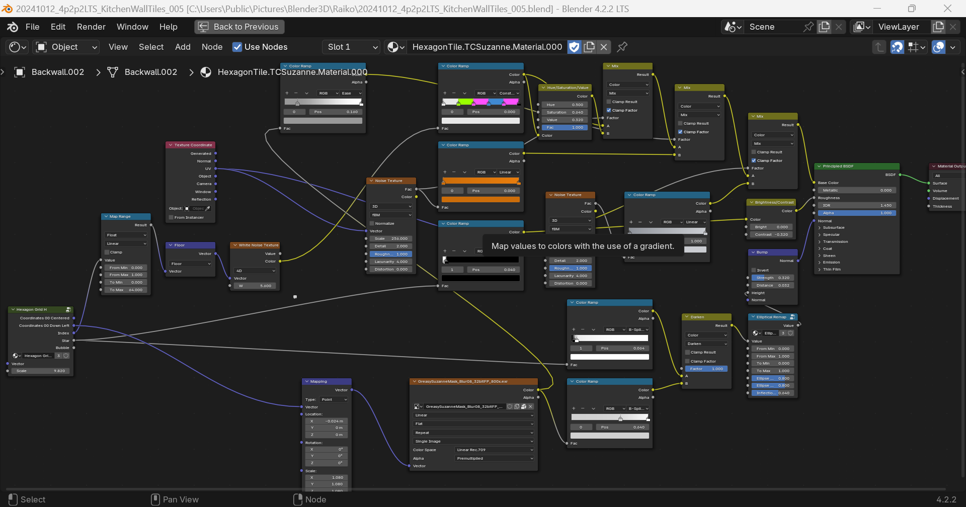
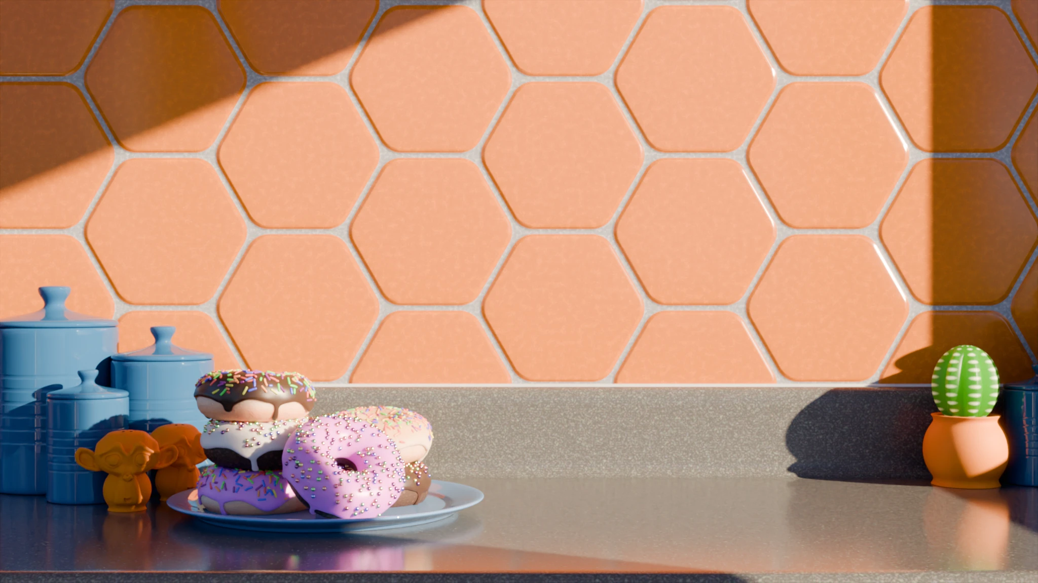
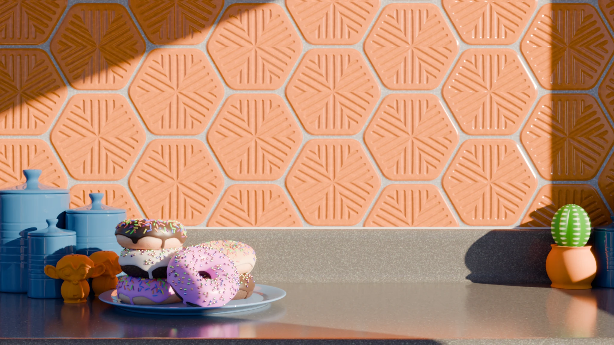
Prior to this topic, some of this was already doable, albeit with complex node trees that could be daunting and/or computationally heavy. I polished up my old hexagon grids Group Node – let’s say I’m gonna render a dish of yummy pastries on a kitchen counter in v 4.2.2 LTS. The back wall seems a bit bland, I want to kick it up a notch with some hexagonal terra cotta tiles:

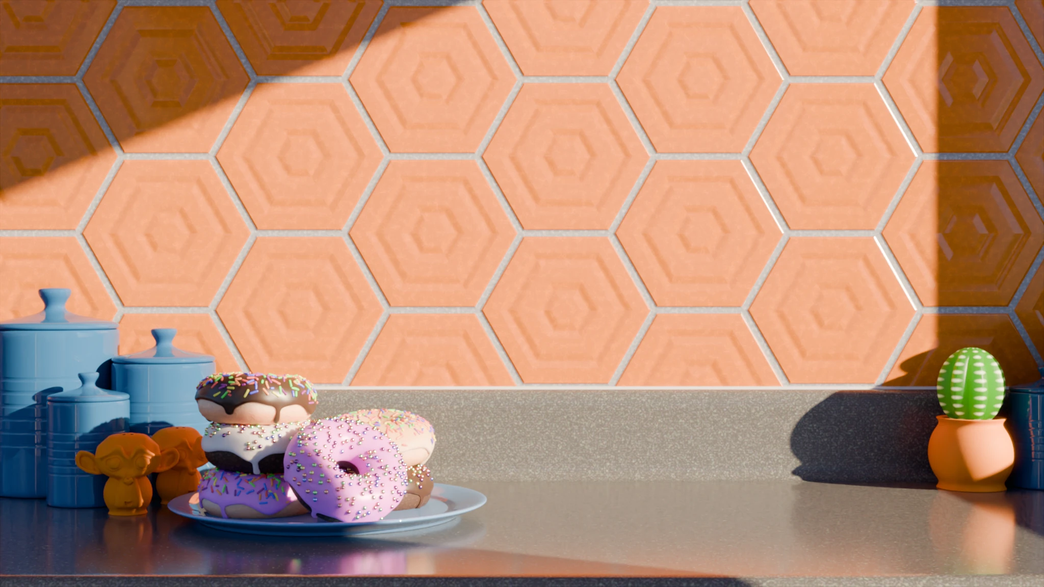
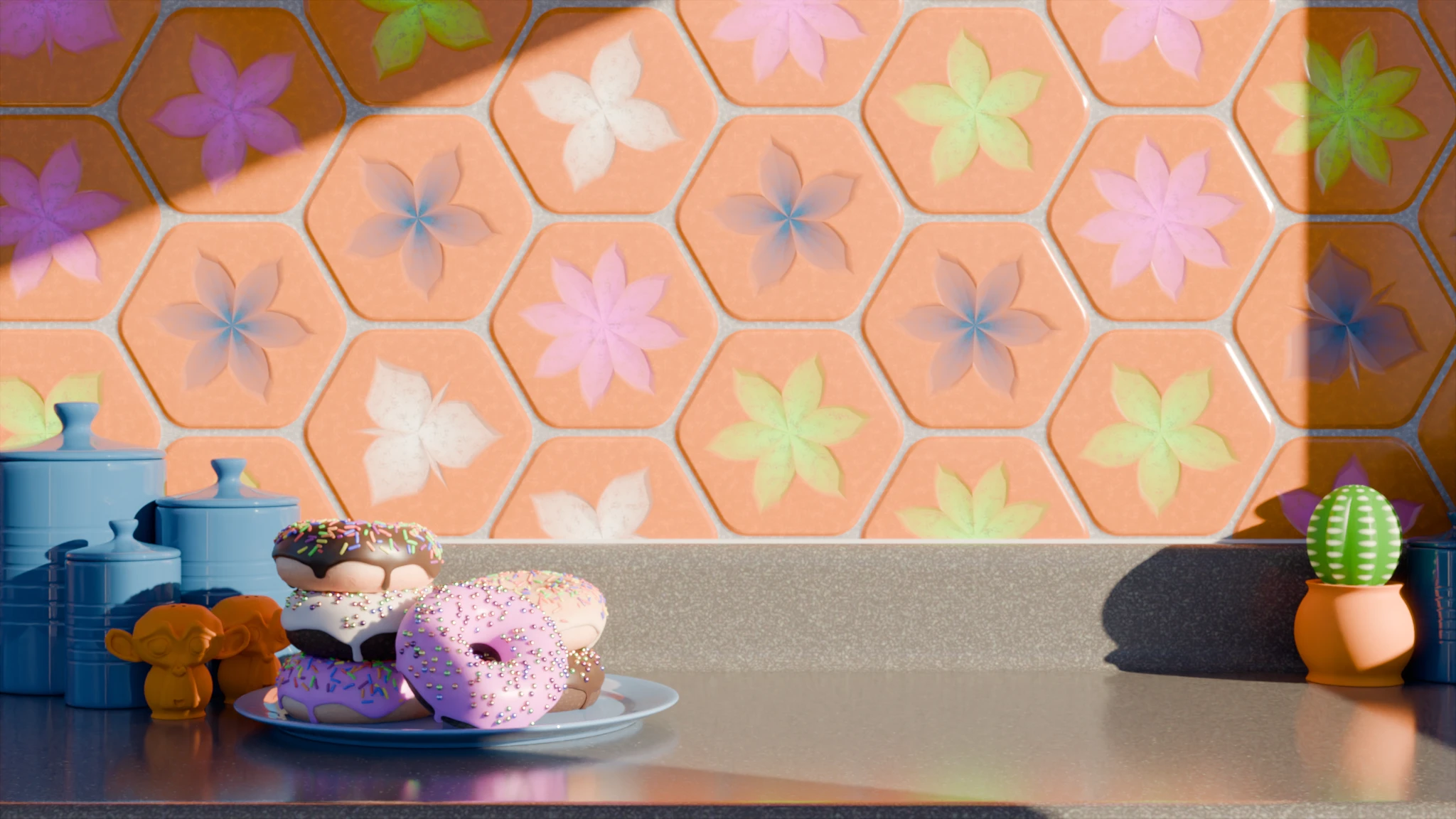
Hey, the Eliptical Remap (et al) node works in earlier versions! I didn’t realize that, sweet. Next I could go with a procedural design in each tile:

Or an image mask (thanks again to Benny_G for the random-color-per-tile nodes):

But that’s the old & lousy way, what about new & improved?!? A better hexagon grid?

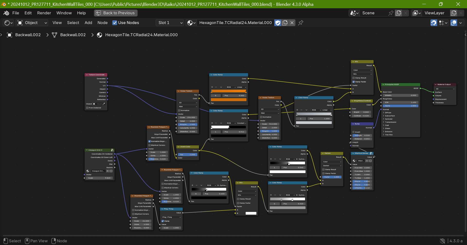
Guess not. Here’s hoping that the “updated version of the grid texture” will do what mine does, but better/stronger/faster (cue the 6m$ Man theme music). Okay, v 4.3.0-PR127711, I’ll use mine for the distribution grid, Rounded Polygons for the tiles:

Smoothly rounded corners, very nice. And the Elliptical Remap node softening the edges somewhat. Now a per-tile decorative pattern:

Thanks again @Benny_G ! Super-snazzy . . . huh, maybe too snazzy for a backdrop. Which is where the radial-ish thing I posted here comes in:

Ah, lovely, if still too sharp – clay stamps don’t usually have mathematically cut edges. The Elliptical Remap node improves some of them, others are as pristinely and obviously calculated as the edges of the Default Cube.

My current conclusions: If all we get from this project is the Rounded Polygon Texture as-is? Still a win, would be happy to have it. A Smooth F1-style option in it would also be very welcome – although I realize the Elliptical Remap node is intended to provide that (or similar) functionality, it falls frustratingly short IMHO.

Here are the blends:

20241012_4p2p2LTS_KitchenWallTiles_005.blend (1.7 MB)

20241012_PR127711_KitchenWallTiles_000.blend (480.7 KB)
8 Likes

It’s this PR: https://projects.blender.org/blender/blender/pulls/125389

Yes, that’s what’s planned, though the repeat zone from geo nodes needs to be ported over to shader nodes first.

I see, you’re using the Edge Parameter output to make those clay stamps. The Edge Parameter output is discontinuous at segment borders, which is where you’re getting the sharp edges from. Additional nodes are needed to remove the sharp edges, which due to the discontinuities isn’t even that easy.
The Edge Parameter output was actually designed to be used as the X-coordinate in combination with the Radius output as the Y-coordinate for radial tiling. Simon Thommes for example suggested replacing it with a radial tiling vector output.

2 Likes

Hey, the next build is up!

1 Like

Yes, but I didn’t have the time yet to make a new demonstration .blend file and to document the new changes.

I’ll post an update in the next few days

5 Likes

Update:
This time there some major updates:


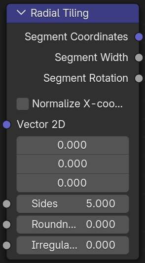
First the Edge Parameter output was replaced by the new Segment Coordinate output, which has the Edge Parameter output as it’s X-coordinate and the Radius output-1.0 as it’s Y-coordinate.
This change was made to make radial tiling easier to set up, to access the old Edge Parameter output just use a Separate XYZ node.
Moreover the Normalize Edge Parameter was renamed to Normalize X-coordinate to reflect that change.

Apart from that the algorithm for the Edge Parameter output (or rather the X-coordinate of the Segment Coordinate output now) got a major update.
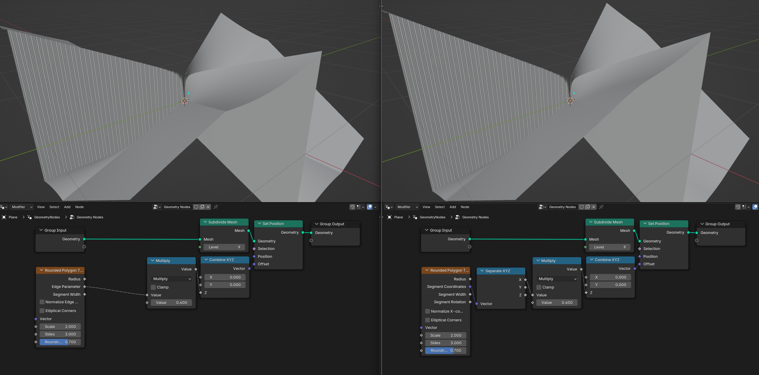
Previously the output wasn’t differentiable at the points where the polygon started to round which lead to creases in the output. I was able to develop an algorithm that ensures that the output stays differentiable even in those points, thereby eliminating those creases in the new version.
Below is a comparison picture. Left side shows the old implementation, right side shows the new implementation.

The Max Unit Parameter output was renamed to Segment Width to give it more visual interpretation.

A new Segment Rotation output was added, which can be used to align object along a certain global direction when using radial tiling.

The Grid 2D Parallelepipedal node group was updated to a better (Prototype) Grid 2D node group. This node group isn’t actually part of the PR and as the (Prototype) in the name suggests is still far away from the planned final implementation both feature and performance wise.
Despite this it now allows for tiling without the need of repeating the node tree 4 times, which the old Grid 2D Parallelepipedal node group needed.
As an example it is now finally possible to create a procedural hexagonal tiling with just a few nodes:

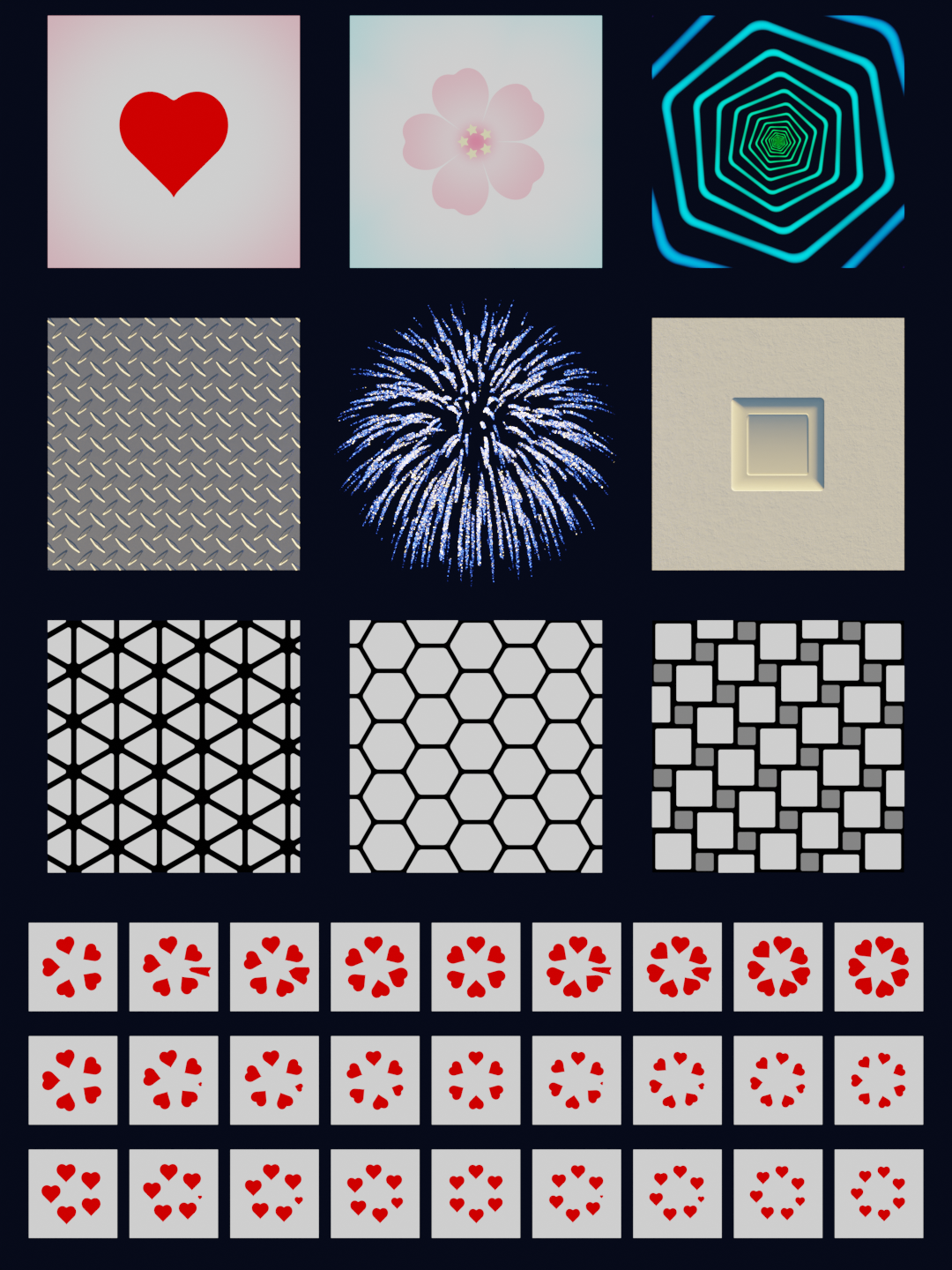
For the new version I updated the demonstration .blend file and added a new example to it:
Download here: https://projects.blender.org/attachments/a9d79bdf-f24c-4f5f-80be-d0f0000bbbb2
When opened in rendered view this is what it looks like:


The firework in the middle is quite expensive to compute, so if you have the problem that Blender becomes unresponsive when switching to rendered view just toggle the visibility of the firework (which is the only cube object) off or alternatively switch the render engine to EEVEE.

Please make sure that you use the new patch build when opening the demonstration .blend file:
Download here: Link to Patch Build

I also updated the user documentation:
Download here: https://projects.blender.org/attachments/cdef7dd6-1825-4fbe-9a42-2f59837dde29

Lastly I noticed that very few people are looking at the demonstration .blend file and user documentation. So if possible, I would really appreciate it if you could have a quick look at them and maybe even give some feedback.

That’s all for this update, thanks for your support as always! :heart:

6 Likes

A quick side note for the new demonstration .blend file:
One of the new examples is a procedural volumetric firework which is quite expensive to compute.
If you have the problem that Blender becomes unresponsive when switching to rendered view just toggle the visibility of the firework (which is the only cube object) off.
Alternatively you could also switch the render engine to EEVEE.

1 Like

Just saw the thread so haven’t tried it yet. But would it be sensible to rename the Vector input to 2D Vector or Vector (2D)? A frequent question is “why isn’t my brick texture working”, expecting it to work with 3D coordinates.

Also, is there a way to use a mask to control if pattern is applied or not? Like, if “center of this tile” is in the white color of the mask, then apply the pattern on this whole tile. I.e. a simple mask to control where a hexagonal hole pattern is applied, similar to along the edges on this example.

I’m guessing Segment Coordinates are coordinates centered on the tile center? That is very useful. But random colors (say from 1D white noise) is also a must, as many of us prefer to do some randomization per tile (i.e. texture position, rotation, and scale lookups).

Good idea, I just renamed the input to “Vector 2D”. The new build now shows that name.

This would be a feature for the Grid node. The current prototype version can’t do it but the final version will have an “Index” output, which will make creating such masks very easy.

This can already be done using a few simple nodes:


There has been a design decision by the Nodes & Physics module that states that functionality that can easily be achieved by using nodes shouldn’t be added as built-in functionality to reduce the maintenance burden of the code.
I agree that a random color output would be useful but I also have to adhere to the design decisions of the rest of the module.

2 Likes

Update:

Hey, it’s been a while. Long story short, I’m still waiting for the Pull Request to be reviewed. It’s been put on the agenda of the next Nodes & Physics meeting so hopefully we can get some progress then.

In the meantime I did some more improvements to the nodes.

First of all, when reading through the use feedback I noticed that most of the time either the Radius output is used as a base texture or the other outputs are used for radial tiling, but seldom are both used simultaneously.
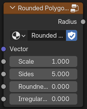
I’ve therefore split the node into two, one to use as a base texture:

and another one to use for radial tiling:


Secondly, as you might’ve noticed from the screenshots the Elliptical Corners option is gone now.
That is because I’ve replaced it with an Irregular Corner Shape input which allows for a gradual transition between the two options.
Irregular Corner Shape = 0.0 corresponds to having the old Elliptical Corners option unchecked while Irregular Corner Shape = 1.0 corresponds to having the old Elliptical Corners option checked.
For values between 0.0 and 1.0 this input is used as a factor to linearly interpolate between these two options.

12 Likes

The Pull Request as been committed. :tada:
Thank you @Raiko . :joy:

7 Likes

Looks like someone already beat me to it, but nonetheless, it is with great pleasure that I’m able to announce that the Pull Request for the Radial Tiling node was merged into Blender’s main branch earlier today. :tada:

The final design that was merged today is largely the same as the one I had presented with the last update on February 8th, with the only difference being that the “Irregular Corner Shape” input has been removed. The reason for it’s removal is quite technical, but in a nutshell, the code for it was too complex which threatened to overwhelm the GPU compilers, potentially leading to all sorts of issues.

The Rounded Polygon Texture node group was not part of the Pull Request that was merged today, so you won’t find it in the daily builds yet. I’ll either open a separate Pull Request for it or have it included in a larger node assets Pull Request. But since it’s just a node group asset, I don’t expect too many complications in the process, so it should also be available soonish.

I’d like to take the opportunity to thank everybody who contributed to the discussion, especially those who shared their use case examples. Not only were they essential for demonstrating the usefulness of the Radial Tiling node to other developers, they also significantly helped in shaping the final design of the node.
Initially I had just developed an algorithm that could output rounded polygons, but later on, I realized that it could also be extended to allow for radial tiling. Since an algorithm that could do both things simultaneously was a novel concept at that time, there wasn’t a clear direction of how the node containing it should look like and my initial design proposals for it were rejected. It was only after analyzing how you guys where actually using the node in your use case examples, that I was finally able to create a design that was approved by all modules.

Here’s to hope that a certain someone isn’t disappointed again that the final design deviates from what was initially proposed. :crossed_fingers: :wink:

25 Likes

Congratulations on getting this merged! I apologize for communicating poorly about this earlier, the design you landed on is well thought out and thoughtfully crafted and I believe it will be a good addition to Blender :slight_smile:

4 Likes

Fantastic! Thank you for your work! :partying_face:

I think this is exactly the kind of smaller building block that’s actually useful to Blender users of all types, as opposed to the initial proposal for the “Raiko texture”. Congrats & thanks for your contribution, this is great !

2 Likes

Thank you very much for your work.
:clap: