The Great Collective Geo Nodes Thread

Hi everyone.
This is intended to be a general community thread where everyone is invited to share their geometry nodes setups/nodegroups they made.

Just two rules:

  1. No showing off without providing either a fully readable, complete screenshot of all relevant nodegraphs (nothing hidden away in mysterious nodegroups), or a clean .blend which contains the nodegroup/-tree.
    That said, do feel free to show screenshots/gifs/videos of the results along with it. Unless self-explanatory, some minimal description what it is/does is advised too.

  2. Always note down which Blender version was used either, especially where recently added features/nodes were used.

.
To kick things off, Iā€™ll start with some boring, non-artistic linear algebra operations. :upside_down_face:

Transform point p from cartesian to barycentric coordinates w.r.t triangle abc in 2D [Blender 4.01]:

.
Find the center of the inscribed circle of triangle abc in 3D [Blender 4.01]:

24 Likes

Hereā€™s a setup by which one can reliably tell geometries apart after theyā€™ve been joined (which may render the elementā€™s indices an unreliable way of doing so) [Blender 4.01]:


It is worth noting the actual order in which the Join Geometry node concatenates the points here isnā€™t something you can rely on here. From my experience, it seems to sometimes depend on the temporal order of connecting the inputs (or maybe that was just a coincidence) and this order may arbitrarily change after saving and reloading a file.

greetings, Kologe

4 Likes

The kind of thread weā€™re trying to restart:

I found a cool way to ā€œglueā€ a mesh to a surface that Iā€™ve been calling ā€œUV Deformā€. Itā€™s similar to the Surface Deform modifier, but this method uses the UV map of the target surface.

In exchange for the UV requirement, it works (in my opinion) much better than the modifier. It retains proper deformation after the surface has been subdivided (because itā€™s bound to the UV coordinates, not the mesh) and new geometry can be added to the surface (via loop cuts, not extruding or merging in new geo, basically anything that doesnā€™t screw up the UV map).

This entire method relies on the Sample UV Surface node, so big thanks to Jacques Lucke who developed it :smiley:

In this video, the red mesh is being bound to the blue surface. Top is Surface Deform modifier, bottom is my UV Deform. You can see Surface Deform falls apart once the target surface gets subdivided and new loops are added.

The way it works is each vert samples the nearest mesh surface and asks for the UV coordinates of that spot on the mesh. The vert stores that UV coord, along with an offset vector between the sampled spot and the vert.
This needs to be permanently written/applied/bound to the verts, it canā€™t just remain in a modifier.


(the group input/output nodes are that color because I donā€™t like them being black)

Then each vert samples the uv map of the target surface, goes to the UV coordinates that it has stored in itself, and ā€œasksā€ those coordinates for their position in 3D space. The vert is then moved to that position, and also offset according to the stored offset vector.

The offset part can be skipped if you just want a flat mesh to stick to another flat mesh, almost like a texture.

It has to be done in two separate GeoNode modifiers:

  1. the binding, which writes the needed information onto the verts, and needs to be applied immediately
  2. the deform, which moves the verts into their new positions

It was pretty clunky with two modifiers and needing to apply the first one every time, but now we have GeoTools that make it a bit faster.

Would be even better if GN modifiers had a way to execute some geometry node stuff via a button in the modifier panel, just like the Surface Deform has a ā€œbindā€ button in it.

13 Likes

I personally prefer a simple blend file instead of a screenshot. Even though I would consider myself to be well-experienced with geometry nodes, I have difficulty understanding even the simplest node-setups by others without hands-on experience. It will take me ages to recreate the incircle node group (for example)

3 Likes

Do you know those brilliant moments, when youā€™ve spent like a whole day desperately trying to figure something out via geometry nodes (to no avail), until it occurs to you:
Thereā€™s that one dead-simple algorithm, which does exactly what you want, only better. And you know it actually exists, and works, and how it works. Because you personally imlemented it in Python a few years ago. And thereā€™s nothing about it you cannot do in geometry nodes. Just thinking of it earlier would have saved yo u hours. :unamused:

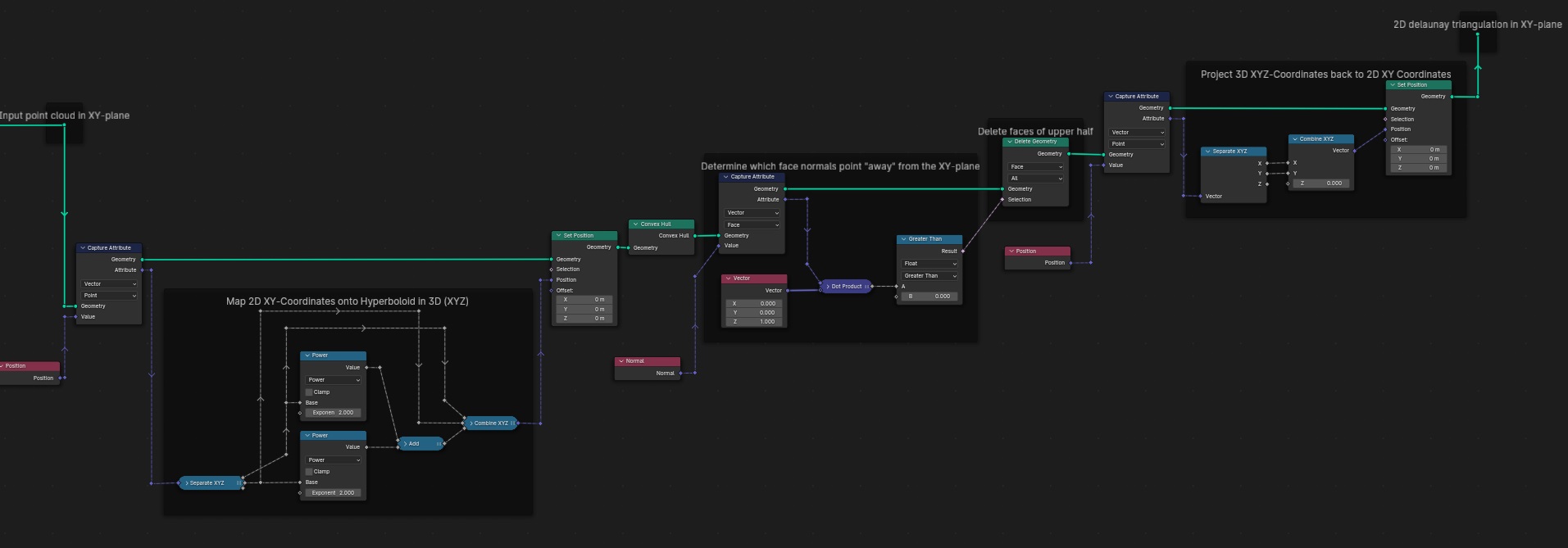
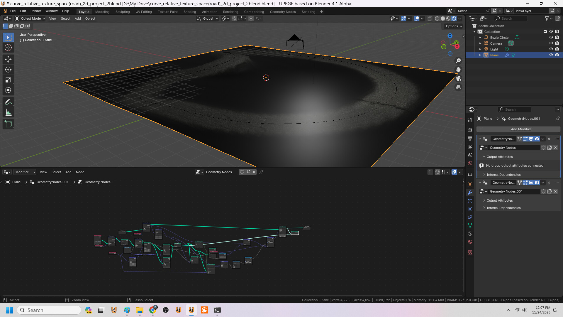
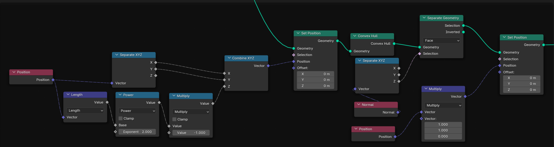
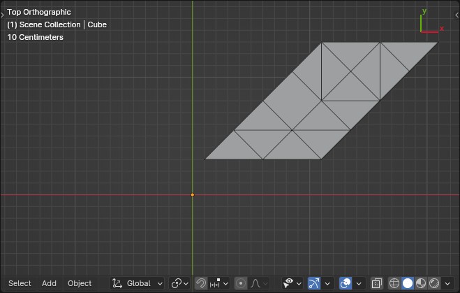
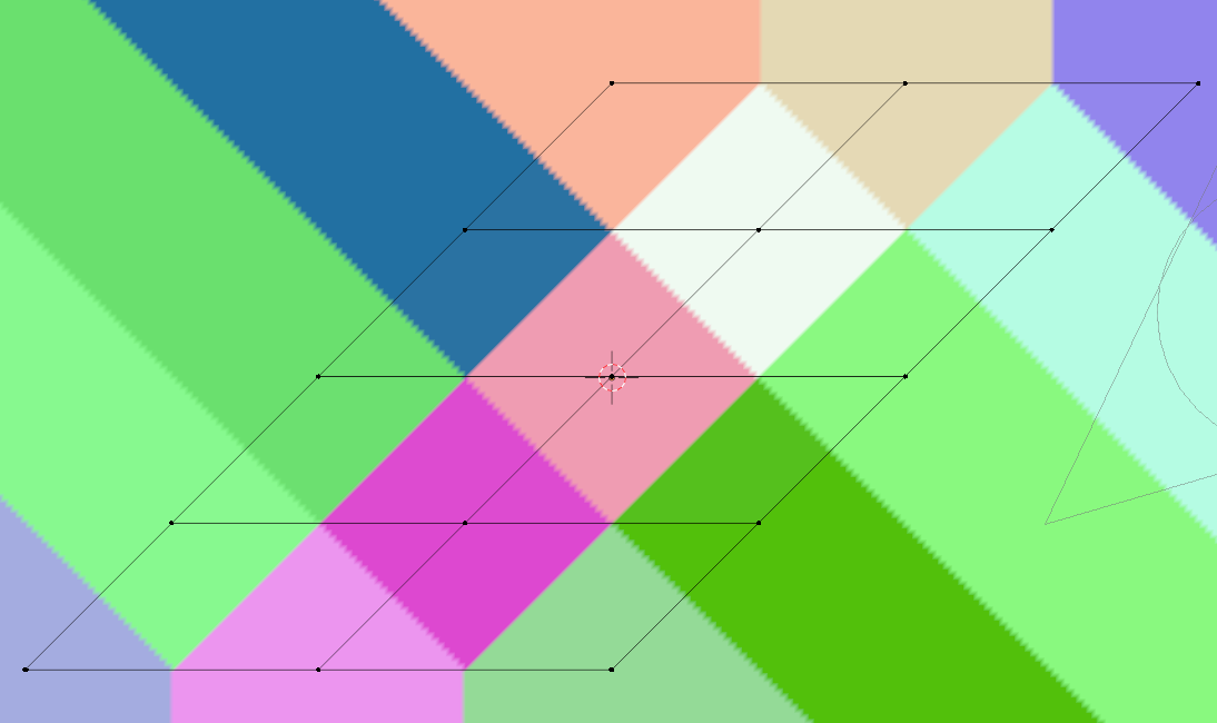
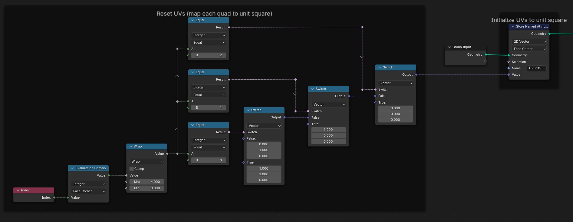
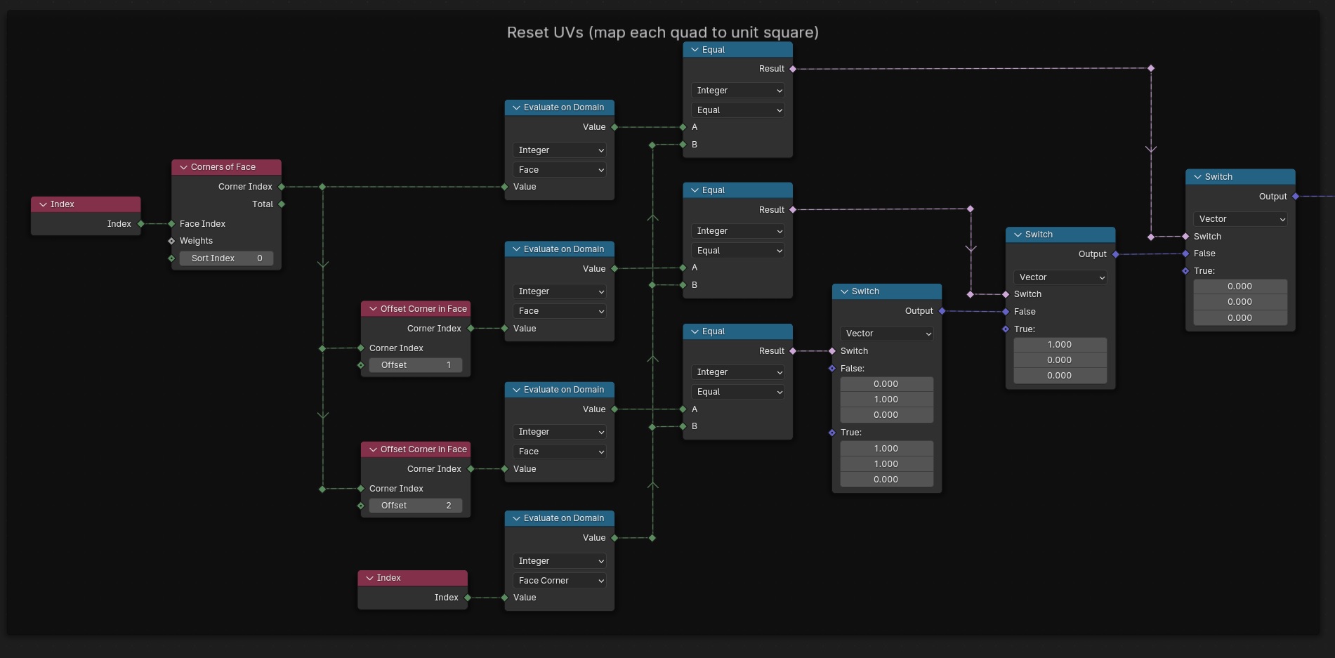
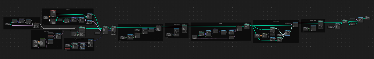
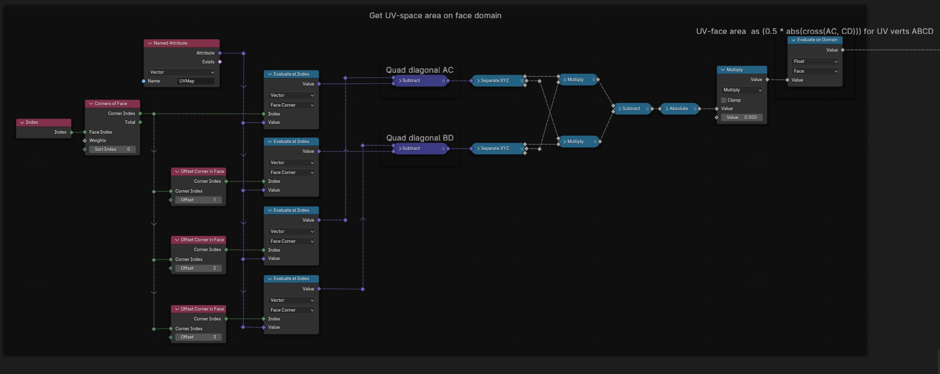
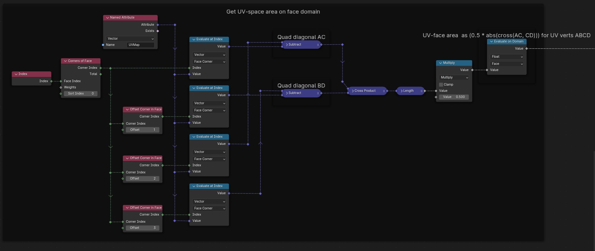
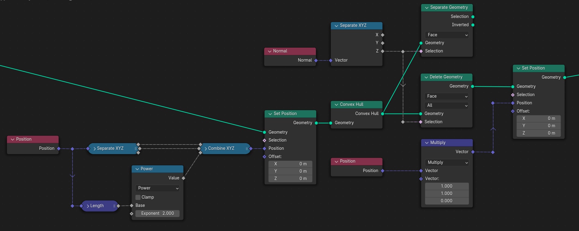
From a set of points in the XY-plane, construct the delaunay-triangulation [Blender 4.01]:

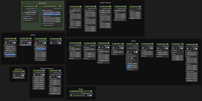
It should be noted all input point coordinates should be > 0 along both axis. Otherwise the fact (-n)Ā² == nĀ² will cause trouble (see the first frame node in the screenshot).

Come to think about it, for robustness a Triangulate node should probably be inserted right after the Convex Hull node in the tree shown above. Else an unfortunate choice of input coordinates could probably cause the Convex Hull node to make a 4+ sided face where 4+ verts might just happen to end up coplanar.


If you wonder why not just use the Fill Curve node and be done with it: The problem is, starting from an arbitrary set of points in the plane, using something like
Points > Convex Hull > Mesh To Curve > Fill Curve
means you loose all the internal points (inside the convex hull).

It would probably work, if you had an order on the points such that the Points to Curve node (given that order via itā€™s Weight input) could make a hamiltonian path over all the points, but that should be hard to come by in practice.

Thatā€™s a fair point, and a thought along those lines occured to me myself just today.
That said, I think screenshots do have their merit too.

Personally, Iā€™d vote for go with screenshots and make the .blend an extra goodie if you like (unless you have it already wrapped into a nifty nodegroup for personal use, making a screenshot is cheaper than getting things into a redistributable state).

At least if youtube videos are anything to go by, many seem to have an unhealthy relaxed attitude towards those curved bezier connections messily criss-crossing arbitrarily and everything being beyond unreadable for that reason alone.
Iā€™d probably spend almost as long reshuffling other peopleā€™s messy graphs/trees into something my brain can actually make sense of, as I would recreating something like the screenshots above node by node.

greetings, Kologe

3 Likes

I often work with 2d meshes and I actually prefer the box quad modelling way to create shapes over the use of curve objects.

So I often want to convert corners into a face loop like this:
(mainly because of the different smoothing behaviour in sculpt mode)

image

This is exactly what this node tree does.
The file contains a GN Tool and a GN modifier (with some extra crease options)

I came up with 2 different methods of corner selection, one detects corners with back and forth domain interpolation - the other uses shortest path. there is a mix factor to extend the merge radius in M2. They behave differently depending on ngonity, distance and angle. Donā€™t know if there is a better way, but it works pretty well for my usecases :slight_smile:

Pre/post subdiv can be restricted to mesh islands with at least 1 vert selected.

GN_round_corners.blend (2.3 MB)

8 Likes

1 Like

I guess thatā€™s fair. But you also have to remember that ā€œreadabilityā€ can be subjective. I find flowing node trees easier to read than those with straight wires going in 90 and 45-degree directions.

Why would that be the case? Even if two points have the same Z, it shouldnā€™t matter. Or am I missing some special case? I recreated your setup and it works just fine.

I also made a vector form version of the incentre node group


Triangulation&Incentre.blend (110.8 KB)

2 Likes

Well for fairly regular input point distributions, it can be problematic, if Iā€™m not misstaken.
Put something like a grid for the input-points and youā€™ll probably not get a triangulation at all as result (let alone a delaunay triangulation).
I will admit offstting a regular grid to all positive XY-coordinates typically only partially mitigates this, but it does help.

Hereā€™s the result when using a paralellogram for input points:
screen

Hereā€™s the result from the same input offset to all positive XY-coordinates:
screen2

Still not exactly a textbook delaunay triangulation (one quad left) but much better/closer.

Now that I come to think about it, you could probably figure out a scalar multiplier to apply to all input-coordinateā€™s XY-coordinates of a magnitude chosen such as to ensure even those (input) points closest to each other will, (after multiplication by the scalar) lie far enough apart in the XY-plane to result in sufficient Z-axis-spread of all points.
Where ā€˜sufficientā€™ means far enough apart the 3d convex hull operation will have to result in all triangles for those faces weā€™re interested in here.
This (I think) would guarantee a dealunay triangulation (other than using a Triangulate node, as I,- somewhat prematurely - suggested above).

Ofcourse itā€™s a matter of usecase weather you actually care if or not the result is triangulated, let alone delaunay.
Note though, if it is the latter, itā€™s quite trivial to derrive the (input pointā€™s 2d-) voronoi diagram from it (might post a setup for that later).

But Iā€™ll be honest: You should take my words with more than a grain of salt.
If math was a woman, sheā€™d be stepping on my toes basically every time I try to dance with her. Not because sheā€™s trying to be mean, just because Iā€™m a lousy dancer. :neutral_face:

Thatā€™s cool, why hasnā€™t that occured to me?

greetings, Kologe

It seems you have chosen a special parallelogram with an angle of 45Ā°. I am curious to know what the correct triangulation would be, as the Voronoi suggests the face would have to be a quad

I guess youā€™re right there. My assumtion why the quad would be this:

An angle of 45Ā° (or a multiple such as 90Ā°) means the four corners are at equal distance in xy from their centroid (= an oblique/straight square). If follows they lie on a circle around their centroid which renders their delaunay triangulation non-existent ambiguous (either is as non-delaunay delaunay as the other, for no matter how you triangulate, both triangleā€™s respective circumcenters coincide / are colocated with each other as well as the squareā€™s centroid. Thus all four corners lie on either of the two circumcircles regardless (the delaunay condition states the circumcircle is considered empty of other points, if they lie outside or exactly on, but never inside the circumcircle)).

greetings, Kologe

1 Like

I made a few node groups that make particles in geometry nodes easier.
blender_gFJN2HRQso

image
These node groups use a few node groups inside so it is hard to make a node graph screenshot where people see what is going on. But you can find the blend file for free on Gumroad and the discussion about these nodes in this thread. :slight_smile:

17 Likes

This does the same thing the Reset option does in Edit-Modeā€™s UV Mapping menu (U - key).
So it maps each face individually to the entire UV-space (if a quad). Iā€™d expect funky results if used on n-gons (who does that?!).
Blender 4.01 (should work as early as 3.5).

Note in order to get the exact same result as the Edit-Mode operator in terms of which face corner is mapped to which unit square corner, youā€™d probably need to swap out some of the vectors set on the Switch - nodes for each other.
I simply didnā€™t bother checking in such detail.

Edit: While the above should work just fine in the general case, it obviously does rely on the implicit assumption the Face Corner indices are in numerical order (e.g. Face Corner index 3 being some quadā€™s fourth corner, Face Corner index 2 being the same quadā€™s third corner w.r.t. the quadā€™s winding order, etc.).

All this (to the best of my understanding) usually applies, but Iā€™m quite sure there must be ways of messing it up (e.g. Mesh > Sort Elements > Randomize should probably be a way of doing so).

That said, while not quite of as much elegant simplicity, hereā€™s a slight variation of the above setup not relying on order of indices at all.
Functionally, it does the same thing still.

greetings, Kologe

3 Likes

Is there a contest for most aesthetically pleasing node tree?

2 Likes

I donā€™t think so, but we wouldnā€™t stand a chance against this:

Back on topic: Hereā€™s measuring a quadā€™s area in UV-space (other than in object space, as the Face Area -node does).
Blender 4.01 (should work as early as Blender 3.3):

You can of course spare a node or two by simplifying to (otherwise works the same):

greetings, Kologe

3 Likes

Any particular reason why you multiply the squared vector by minus one before assigning to the Z-coordinate (prior to first Set Position -node)?

It would simplify things if you omitted that Multiply -node and either went with a Delete Geometry -node in place of the Separate Geometry -node, or just pick the latterā€™s Inverted -output instead. Like so:

Am I missing something?

greetings, Kologe

If I remember correctly, that way the normals face upwards

I was asking the same.

I integrated Peter Pā€™s Camera Fulstrum Tutorial , Kammerbildā€™s Distance Culling Tutorial, and we:teachā€™s WINDY GRASS Tutorial to create a field of wheat that culls the foliage/dirt mounds based on camera view and distance, and blows realistically in the wind through noise and wind speeds. Inside the Geo Node setup is also a Separate Geometry node that is unconnected that when the ground mesh is connected, it also culls that mesh geometry as well. I have it disabled as for this scene, it was better to have a low-poly ground plane than subdivide it so it culls properly.

Made in Blender 4.0.

Test Video

Geo Nodes .Blend

This is my first time sharing geo nodes so please let me know if I set the file up wrong or something, I appreciate learning!

2 Likes