Hey, guys. I would like to ask a way of creating recursive subdivision using Sverchok. What would be the workflow? Thanks in advance!
ok, maybe Waffle then…
My idea is/was to design an organic, sliced wooden bench and provide separate slices dwg’s for further /CNC/ processing. Since its rather unlikely I define it by number-maybe Waffle node helps…??
The bench can be designed as as solid or shaped, sliced elements.
Question is: how prepare the design to make it possible for Sve processing?
1 Like
The layout can look in this way. Here random polygon is subdivided on each iteration.
random subdivision loop.blend (1.3 MB)
2 Likes
In this case I would suggest to use Bisect node. With the node it’s possible to cut mesh into slices with required step.
1 Like
if you need exacrtly waffle - use Examples → Parametric Modelling → Waffle
If you need only bisecting use Examples → Design → Panno
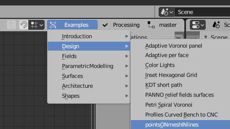
definetly i should create CNC examples item to collect all that stuff
2 Likes
I might be nice case study-ie direct implementation of BL design into production process…
Diz iz generally GREAT. But…
Its unlikely anybody defines input design by only typing numbers…
Need to make it absolutely simple: an object/objects created using regular BL tools
then to be transformed using Sverchok…?? IMHO
I mean it would be nice to plug-in with some ObjectIn just before PANNO frame?
Then only sliceing matrix is left to be defined…
Mister, yes-we can?
Btw. All the Modifiers need to be applied prior to Sverchok?
Id ask another question: maybe instead of slicing, its enough to count&project given elements-
-as in given examples?
What SV-template could be started with?
Thats my case: Curve modifier problem - how align?
Hey, thanks. It wasn’t what I’m looking foward, I was thinking something like this: https://youtu.be/GhquYJ9m1Oc
3 Likes
Thank you very much. Exactly this! 
Some interesting (perhaps useful) examples here of node usage (2020) (Blog):
The site is Japanese. The node examples are in English.
Here too:
(Twitter)
2 Likes
Very instresting site!
Thanks for share
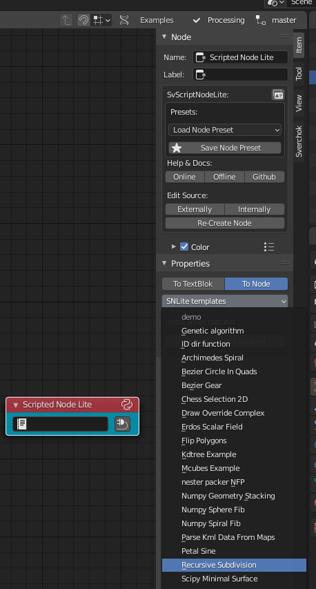
it is simple - you remove generative part and add object in to correspond sockets
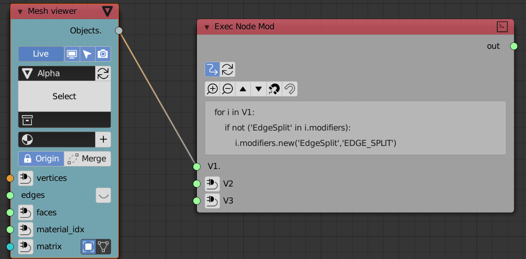
modifiers can be assigned with exec node for now:
for i in V1:
    if not ('EdgeSplit' in i.modifiers):
        i.modifiers.new('EdgeSplit','EDGE_SPLIT')
2 Likes
Hi all!
Im very new to Sverchok but I really want to get good at it, it seems so awesome and I think I would love it as a creative tool.
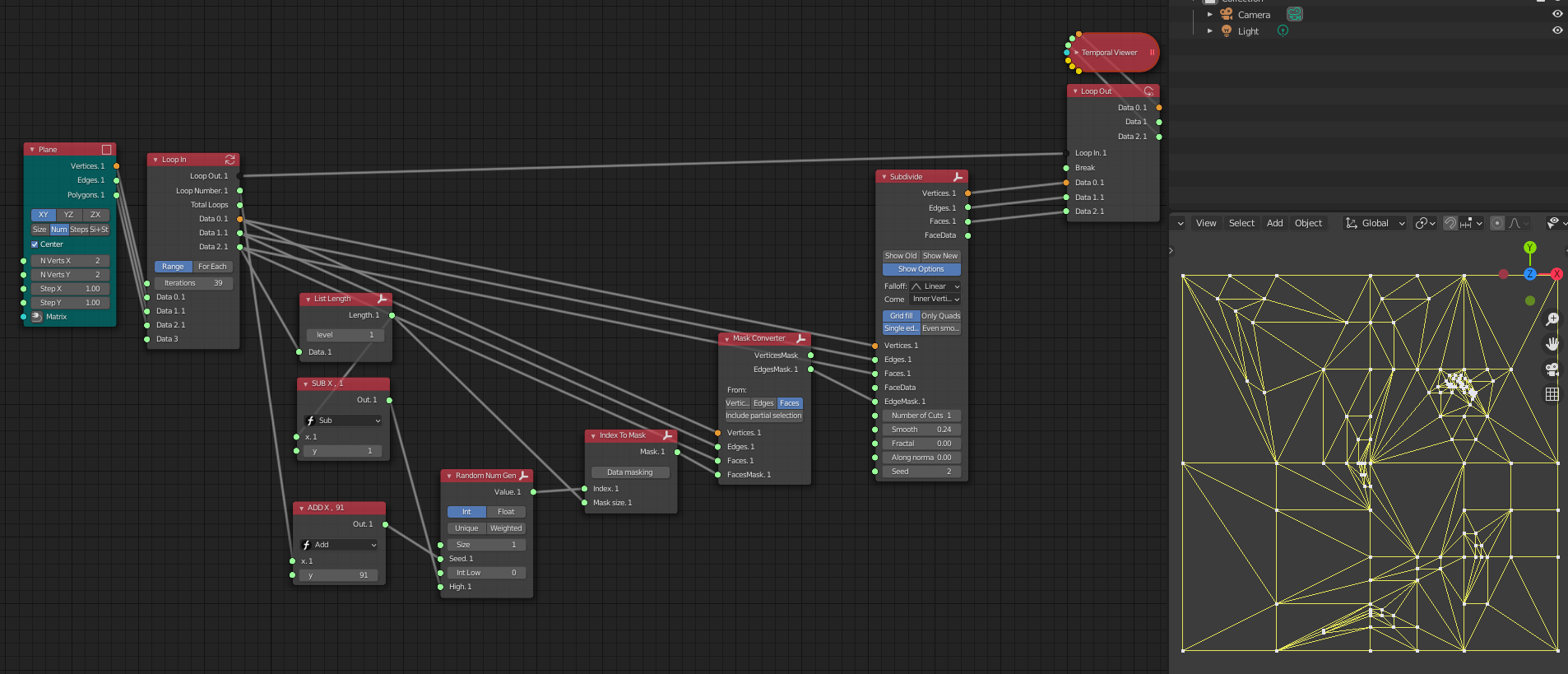
I have a question for you about lists and masks. In my example down below, I have made a form with a grid of faces, which are represented by face number in the image, and then I have another mesh that I have put on all of these faces, the small one in the right. Now, I want to be able to control specifically which faces this mesh is attached to. Forexample 220-260 .
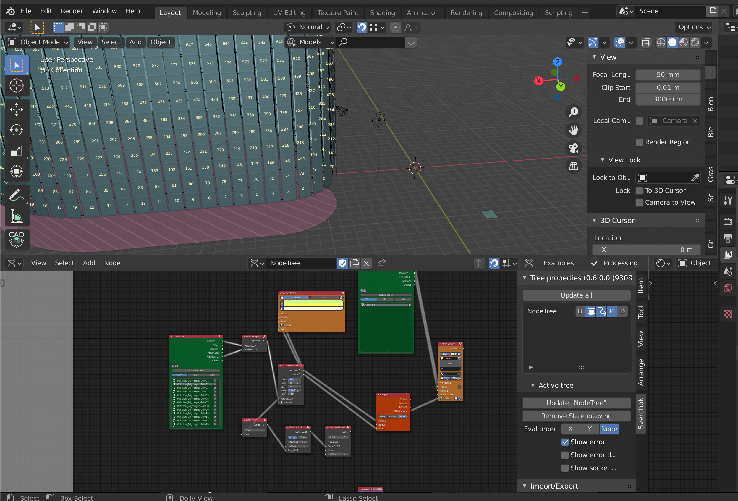
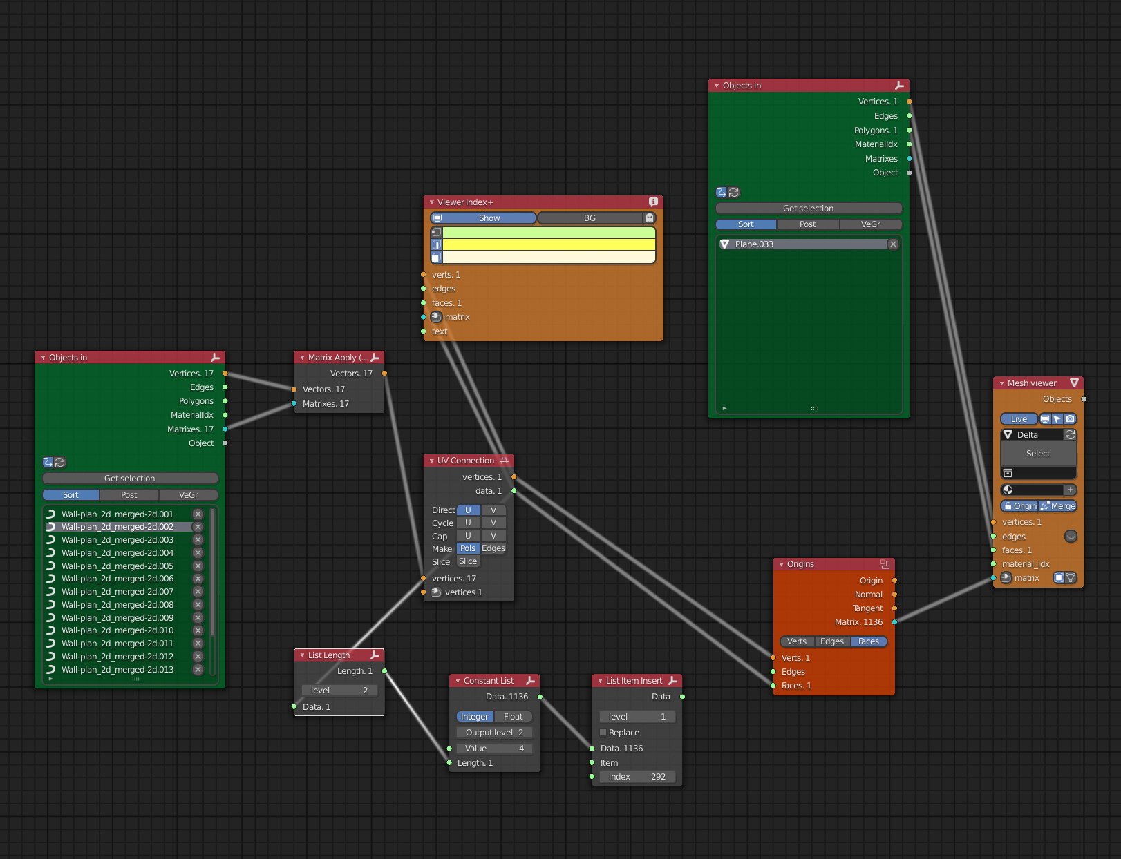
How would I do that if my node setup looks like the next image I attached, do I create a list mask for the origins node somehow ?
Really appreciate any advice here! Thanks!!
Cheers
CG
1 Like
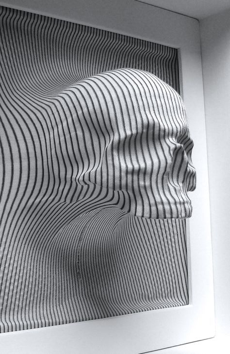
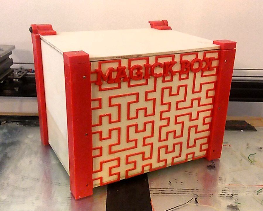
Eventually I printed It out…
First sverchock-freecad design… humble design, but you never know, it’s still a solid and usefull box…
THE MAGICK BOX
so next design will be more complex, I m thinking about a lamp… Same workflow:
Freecad:
Define design structure
Sketches of base constraints
Product parts modeling ( Electric enclosure / ISO lamp ecc)
Modeling of the link component
Sverchok:
From Link component interface →
Procedural modelling of the external structure
Batch export of stl to 3d print
Batch export for 2d cutting (SVG)
4 Likes
Hi All,
I have a facade where i want to place some new faces on, the grey ones in the image. I use the origins node .- matrix to place the rectangular plane on each surface in blue. But somehow the rectangle is not oriented in the same direction on all the blue faces as you can see, how do I control this so that they all become similar, and does it have to do with the normals ?
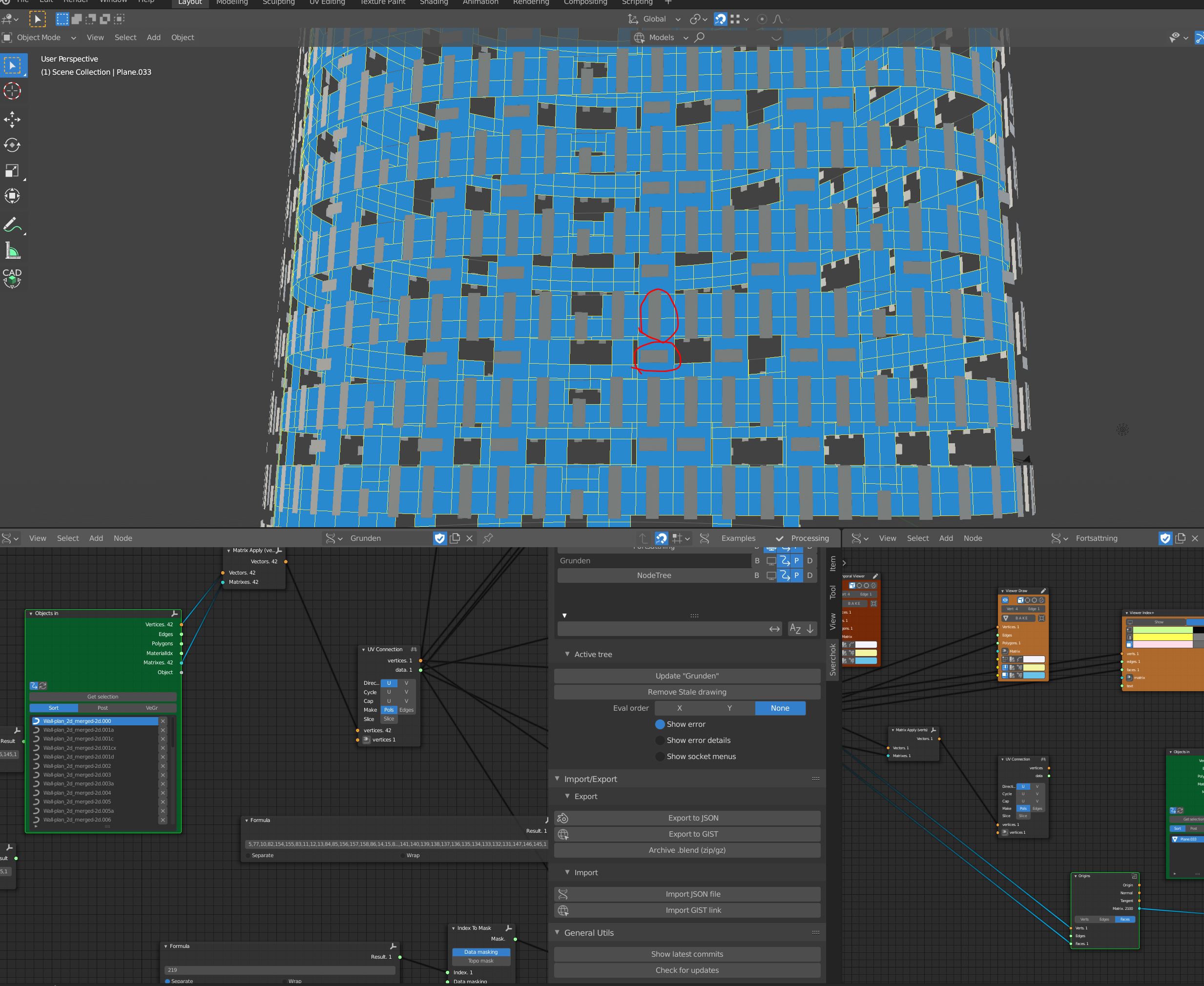
Cheers
The reason of such output of the origins node is that direction of tangent depends on many conditions. An implementation of the node uses build-in Blender methods. I can’t say exactly how these methods determines tangents. Tangents can depend on a polygon topology and its shape.
In your case solution could be to build your own matrixes with matrix normal node. It will let you control tangents direction which in your case should be parallel to Z axis.
1 Like
Thank you Randum for your help! Much appreciated!
Kind regards
CG