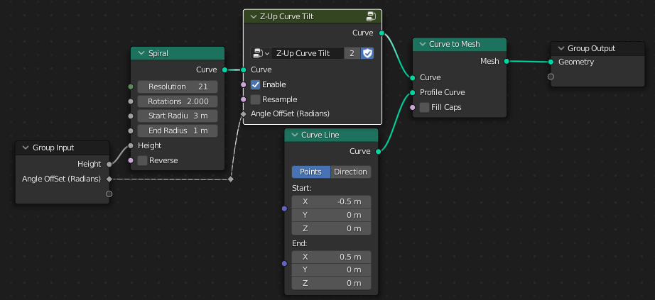
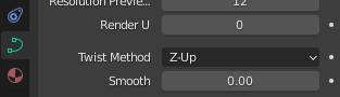
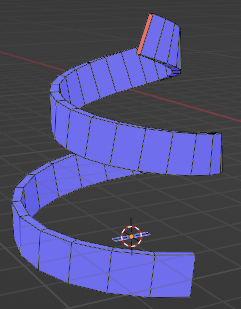
For Curve Objects you have the Z-Up “Twist Method”, but currently (in version 3.0) when using curve-to-mesh or attempting a off-set curve, there is nothing similar inside Geometry Nodes for generated curves (or curves generated from meshes). Apparently this will be implemented as a standard feature in future, but in the meantime hope someone will find the NodeGroup included in the above file useful:
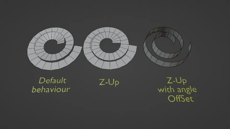
A simple curve-in-curve-out NodeGroup that sets the tilt of the curve to conform to the global Z-Up axis.
Angle off-set is included as a Field Input in case you want to add twist noise or whatever you can dream up.
For curves with sharp bends, the “resampling” option helps (resamples to evaluated, so keep that in mind).
File includes a general Curve-Offset example also (Which becomes doable once the correct twist-angle has been figured out (its then just offsetting all points by the scaled Normal)). Not the best implementation of a Curve-Offset, but works ok if you don’t make the offset too large.
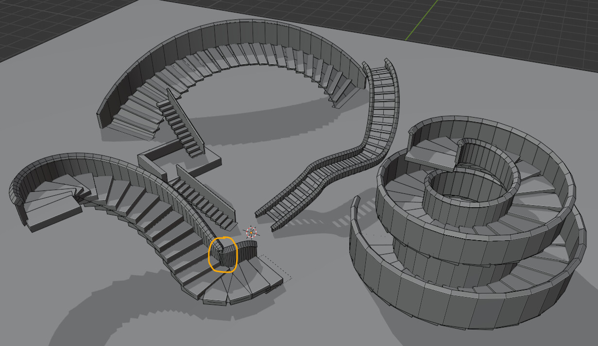
Hope this helps someone struggling to make a parametric spiral-staircase or whatever.
Hah! That’s exactly what I am doing right now. Building a generic Staircase generator. I read here frequently but found this topic via google
So thank you very much for this. It helped me quite a bit*. I even conquered some of the math behind it. (sometimes it really helps to just know the correct search terms for your problem)
Praises aside… your nodegroup still doesn’t completely give me what I am going for. I hava a spline that I use to shape my handrail and to instance the rods of the rail.
Now I want to create a switch for a solid railing by extruding a quadrilateral along the handrail curve. However I still have a slant. I just want the top and bottom points of my profile curve to be aligned vertically on the z-axis.
so is there a way, to cancel that rotation too?
and I am still not getting the tilt factor. How does it correlate to the tangent and the normal? I feel like I am counteracting something that shouldn’t be there - and in a hacky kind of way.
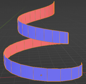
Sorry to hear. If you were to convert the raw spiral to a standard curve object and use Blender’s Z-Up Twist Method with a rectangular bevel object, you’ll get the same result:
…so, unfortunately, all my NodeGroup achieves is what Blender’s built-in Z-Up Twist Method does, but for Geometry Nodes’ Curves (and not a lot more than that…).
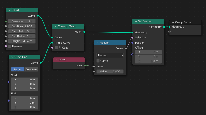
Not as a feature of the NodeGroup, but for your specific case, you can just re-use the curve and use a set-position node with a constant z-offset.
It doesn’t really… by default, the tilt is always 0 everywhere on the curve… the tangent points along the curve and the normal sticks out 90-degrees (as the name suggests) and by default is calculated using the minimal method - which is the one which gives the most “natural twist” (the default, and leftmost example from previous post)… but I’m guessing you’re asking how I get the tilt required to make the normal be always horizontal?
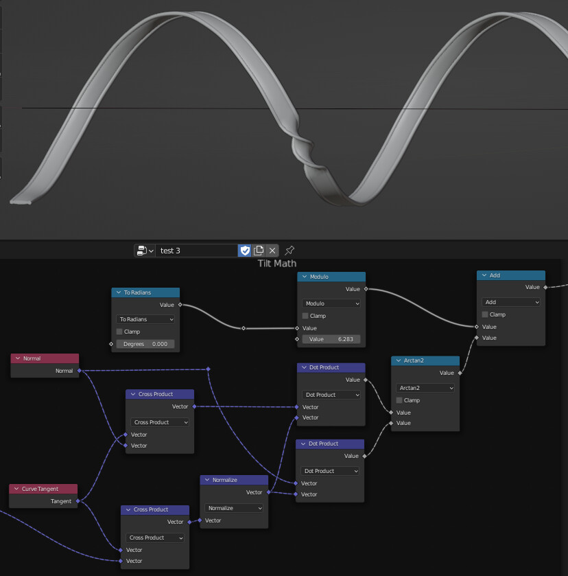
If so, the hand-waving explanation: The tangent, the normal and the local-up (which is constructed as the tangent-normal-cross-product) define the local-basis-frame for some point along a curve. The tangent crossed with the global up vector, normalized, defines the Z-Up normal (which should be pointing horizontally). The tilt is then just the angle between the actual normal and the Z-Up normal. (I use dot-products between the actual normal and the Z-Up normal and the local-up and Z-Up normal and the arctan2 to calculate the angle). For full explanation just tab into the NodeGroup - it’s in the group called “Tilt Math”.
So, to expand on my previous answer, I suggest you should only be using the “Z-Up Curve Tilt” NodeGroup to get the horizontal-width-offset curves of your staircase, and standard instance on-points with Align-Euler for vertical-bars, and set-position with z-offset for railing-curves.
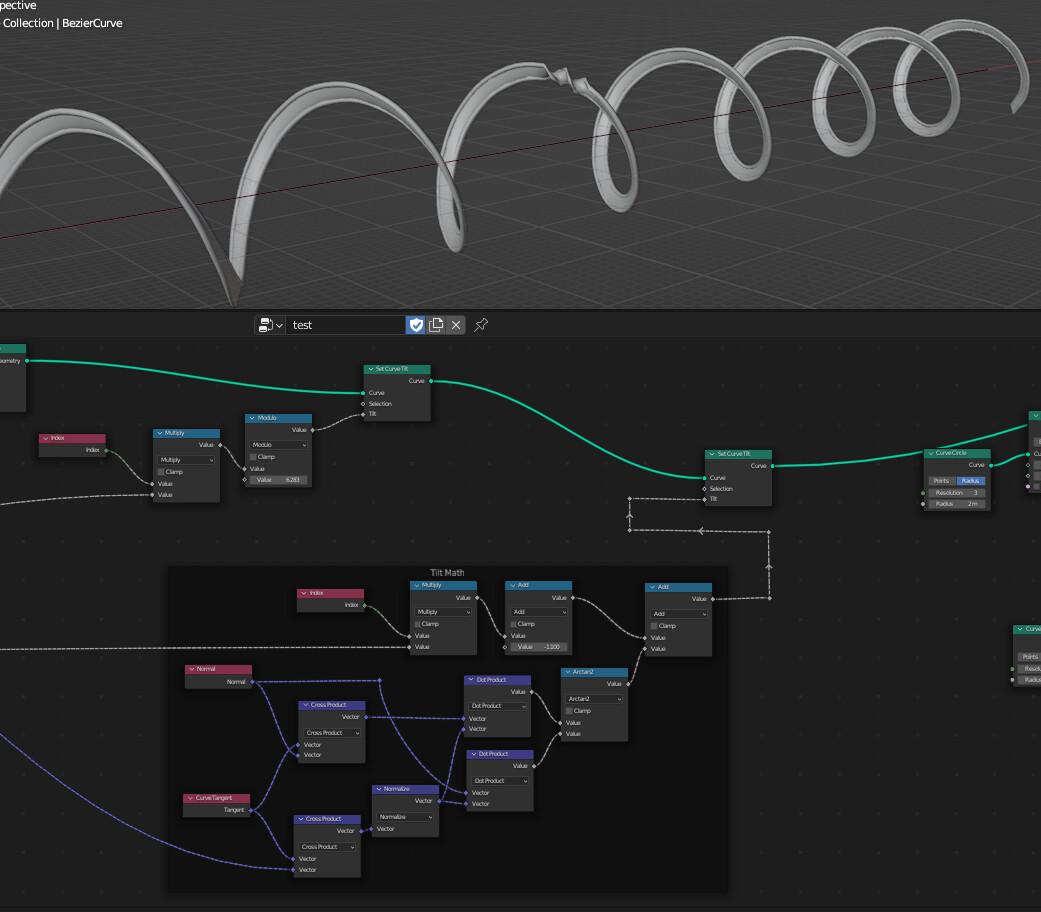
The other possibility for side-sections doesn’t require tilt calculations but does require horrible index-based math (until we can use the extrude node in 3.1 which should simplify this a lot):
…like this:
hey! thank you so much for your detailed explanation. I will need some time to digest everything, I already examined your file pretty thorúrougly. And yes! I also went into that modulo index aproach and it got even more convoluted with a quad as a profile…
at least the extrude node is back on the horizon. I played around with it in the expermental build. it would ease some pains for sure
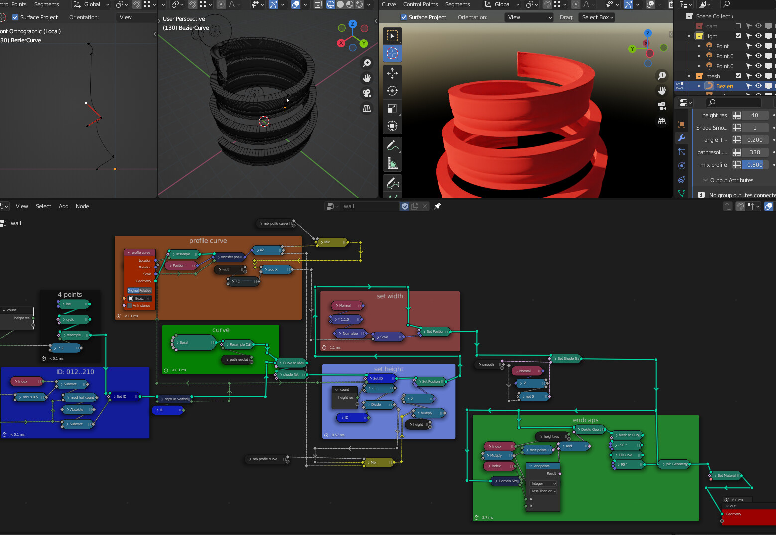
so at least I learned a lot about vector math, but nothing got me quite there, so I just went the indexed way. It is hacky and I created the caps separately because it flickered at certain settings, (which doesn’t work properly right now at non integer revolution settings for the spiral for reasons unknown to me. Until the extrude node comes out I am going for separate endposts I think)
but this is what I’ve got, and I got quite seasoned with the whole ID setting stuff.
I already implanted it into my super stair generator. Also I try to get used to cleaning my trees as soon as I change something or else I will create a unintelligible spiderweb of noodles in no time. I happen to like it actually. It is like zen gardening…
Anyways thanks for your input. It was very helpful. Good night
I’ve fallen down a rabbit hole dealing with offsetting Bezier curves… Sharp turns can “pinch” wildly (circled above).
I have a partial solution involving pre and post resampling the curve and then “auto-Beziering” it again and its good enough (if tweaked).
BUT, just discovered how to do deltas (Index math is becoming a theme) so want to see if there’s a way to offset the curve by scaling the handles also (so, without resampling)…
Predicting failure and settling for the partial solution.
rabbit hole. yes. rabbit hole doesn’t even come close. This is a bottomless barrel
I have learned so much about stairs. haha. Sometimes the biggest problem is that I am not even sure how all of this should behave in certain corner cases.
anyway my stair genarator project progresses real fine.
I have successfully integrated the solid railing and simplified some overcompicated stuff that I made. and I got the escalate stuff working. I am kind of proud
now comes custom stairs from a collection, tapered to the curve. Blinking lights would be nice. I have some ideas.
I have an idea for that yellow circle of yours too.
Hey, I am planning to do a walkthrough through the whole nodetree. I am not the best when it comes making tutorials though. Also there are still things in it, where I think I went a too complicated way. I want to iron them out first. Do you have anything specific you want to know in the meantime?
Thanks for your reply. Actually I want to add spiral staircase in my project. But I’m stuck in stairs like how did you control width, height scale, rotation and z axis up.
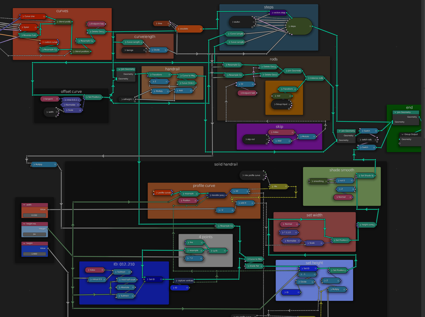
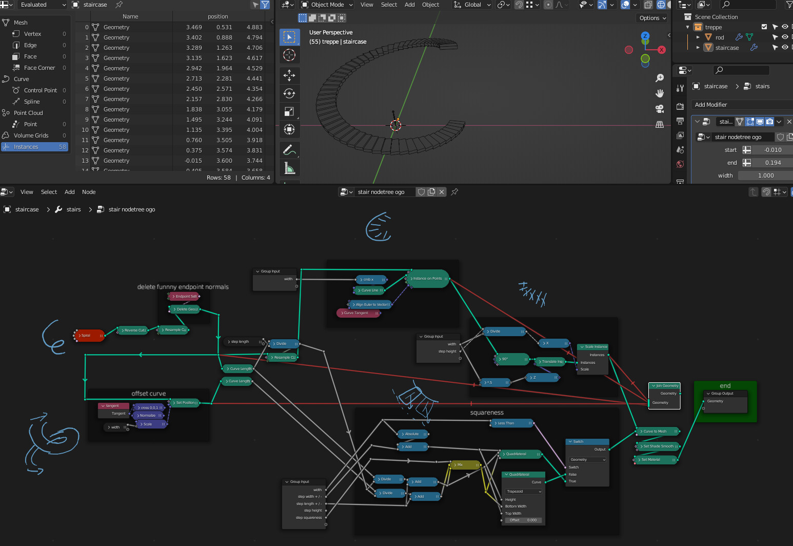
I just stripped the whole tree down to the stairs generation - which was a pretty good idea because I discovered quite a few unneccessary nodes and bugs.
I am not happy with the trapezoids. Started working on custom steps with profile curve from the side. you wouldn’t need to rotate the horizontal line instances like here.
…btw I thought in order to offset the curve I could just scale it along the normal. but it behaves slightly differently it seems. At least with some types of curves.
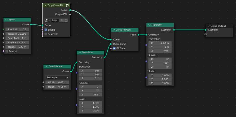
… (NEW!) NodeGroup “Z-Up-Curve-To-Mesh” included in the file above. As a bonus, includes a updated Z-Up-Curve-Tilt NodeGroup which now preserves the Tilt parameter and exposes it for nodes that want to use it later.
Z-Up-Curve-To-Mesh NodeGroup Features:
Similar in operation to regular Curve-To-Mesh Node but profile is projected to the Z-Up local frame of the curve.
Respects regular Curve Tilt and Radius field curve-parameters for predictable results.
Convenience Flip-Normals option added since there is a inconsistency between a regular curve object’s “Bevel Object” and GN’s Curve-To-Mesh’s “Profile”.
Who cares?
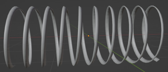
This method of extrusion is not good for curves that are vertically steep, but for architectural objects that generally orientate in the Z-Up local frame this should simplify many GN constructions from curves… So, this may interest people who are making their own Geometry-Nodes Arch-Vis constructs.
Hi @zeroskilz ,
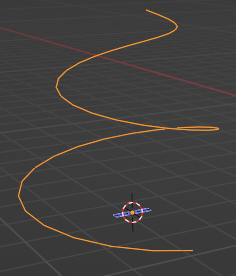
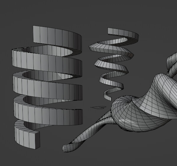
Thanks for the tilt math, it was helpful to me. I tried to modify it to control the tilt along custom vector instead of the z axis. It seems to work well, except for a few random twists that you can see in the image. Do you know what is going on here and how to fix it?
Cross product between unit vectors has magnitude 0 to 1. That should tell you what is going on…
So using only cross product there is no way for the curve tilt to tell how many revolutions have gone by so when the curve completes a “loop” it resets to 0… hence the 1 turn twist when that happens - and that twist will always be the same size as your curve resolution where the “reset” happens.
You’d need to keep track of how many turns your custom normal has made and add that (in units of tau) to the curve tilt also.
Can’t really help you with that as that will be heavily dependent on your setup.
Internally, Blender’s Curve Normals and Tangents are calculated relative to the Z-Up direction and the profile is defined in the X-Y plane, (so that also assumes a Z-Up direction). So it becomes non-trivial to construct things with different conventions. You would need to compensate for the profile tilt to align also in your case it seems…
A simpler construction for what I think you’re after would be something like this: